EP0343692B1 - Test piece coloration comparative decision unit - Google Patents
Test piece coloration comparative decision unit Download PDFInfo
- Publication number
- EP0343692B1 EP0343692B1 EP89111626A EP89111626A EP0343692B1 EP 0343692 B1 EP0343692 B1 EP 0343692B1 EP 89111626 A EP89111626 A EP 89111626A EP 89111626 A EP89111626 A EP 89111626A EP 0343692 B1 EP0343692 B1 EP 0343692B1
- Authority
- EP
- European Patent Office
- Prior art keywords
- color
- generating
- test
- switch
- test sheet
- Prior art date
- Legal status (The legal status is an assumption and is not a legal conclusion. Google has not performed a legal analysis and makes no representation as to the accuracy of the status listed.)
- Expired - Lifetime
Links
Images


Classifications
-
- G—PHYSICS
- G01—MEASURING; TESTING
- G01N—INVESTIGATING OR ANALYSING MATERIALS BY DETERMINING THEIR CHEMICAL OR PHYSICAL PROPERTIES
- G01N21/00—Investigating or analysing materials by the use of optical means, i.e. using sub-millimetre waves, infrared, visible or ultraviolet light
- G01N21/17—Systems in which incident light is modified in accordance with the properties of the material investigated
- G01N21/25—Colour; Spectral properties, i.e. comparison of effect of material on the light at two or more different wavelengths or wavelength bands
- G01N21/29—Colour; Spectral properties, i.e. comparison of effect of material on the light at two or more different wavelengths or wavelength bands using visual detection
- G01N21/293—Colour; Spectral properties, i.e. comparison of effect of material on the light at two or more different wavelengths or wavelength bands using visual detection with colour charts, graduated scales or turrets
-
- G—PHYSICS
- G01—MEASURING; TESTING
- G01N—INVESTIGATING OR ANALYSING MATERIALS BY DETERMINING THEIR CHEMICAL OR PHYSICAL PROPERTIES
- G01N21/00—Investigating or analysing materials by the use of optical means, i.e. using sub-millimetre waves, infrared, visible or ultraviolet light
- G01N21/01—Arrangements or apparatus for facilitating the optical investigation
- G01N2021/0181—Memory or computer-assisted visual determination
Definitions
- This invention relates to a unit for deciding the coloration of a test piece by comparison with reference samples.
- a unit is typically used for biochemical tests (such as a urine sugar test, a blood sugar test, or a urobilin test) and is hereinafter referred to as "a test piece coloration comparative decision unit", when applicable.
- the invention relates to a test piece coloration comparative decision unit which is used for making a decision concerning the coloration of a test sheet (reagent part) impregnated, for instance, with urine which test sheet is then compared with a plurality of reference sample colors in order to determine sugar content in the urine.
- the coloration of a test sheet is determined by a non-electronic color comparative decision system in which an operator visually reads the coloration of the test sheet, or with an electronic urine sugar meter (an electronic biochemical measuring instrument) which comprises, for example a reflection sensor, for automatically reading and displaying the result of a test sheet coloration.
- an electronic urine sugar meter an electronic biochemical measuring instrument
- Fig. 4 is a perspective view showing a conventional non-electronic test piece coloration comparative decision unit. It comprises: a cylindrical case 72 with a cap 71; and a sheet-shaped comparing color sample part 73 bonded to the cylindrical outer wall of the case 72.
- a number of test sticks (each comprising a resin sheet, and a test sheet 75 impregnated with a reagent and bonded to one end of the resin sheet) 74 are accommodated in the cylindrical case 72.
- the cap 71 is removed from the cylindrical case 72, and a test stick 74 is taken out of the case 72. Then, the test sheet 75 is impregnated with urine.
- the test sheet 75 Upon impregnation with urine, the test sheet 75 shows a color reaction according to the content of sugar in the urine.
- the color of the test sheet 75 thus treated is compared with various colors provided in the comparing color sample part 73 on the cylindrical case 72, for the purpose of deciding the coloration of the test sheet. That is, in the color sample part 73, various color samples (for negative and positive signs) 73a provided separately according to the content of sugar (grape sugar) in urine are arranged in a plurality of lines.
- the color of the test sheet 75 thus treated is compared with the variety of colors 73a in the color sample part 73 in order to find the same color (or a color substantially similar thereto), whereby the coloration is determined. More specifically, it is determined whether the content of sugar in the urine is more or less than a standard (or negative or positive).
- a reflection sensor which includes a light emitting element and a light receiving element.
- the light emitting element such as a light emitting diode
- the light receiving element such as a photo-transistor
- the first described, non-electronic, test piece coloration comparative decision unit is formed merely by bonding the sheet-shaped color sample part to the outer cylindrical wall of the test stick accommodating case (i.e., the cylindrical case). Therefore, for a color comparison, the test stick impregnated with the urine is held with the fingers and placed successively beside the various colors in the color sample part until the same color as the test sheet or a color similar that of the test sheet is found. That is, in the color comparison, the operator must incrementally move in fine steps the test sheet impregnated with the urine, i.e., the used test sheet, along the color sample part with a very small gap between the color sample part and the test sheet which requires considerable dexterity. Furthermore, in the color comparison, the test sheet is liable to shift from the color sample, and therefore it can be difficult for an operator to accurately decide the delicate color difference between various colors of the color sample part.
- the reflection sensor receives the color reaction light quantity of the test sheet, and the sugar value is automatically displayed according to the color reaction light quantity thus received. Therefore, with this device, the labor and time required for operation of the coloration comparative decision unit, and the operation of referring a mean value (urine sugar value) of a selected color to a comparison table to decide a color value (or a negative sign or positive sign) can be eliminated.
- the electronic biochemical measuring unit is disadvantageous in that, since it employs a reflection sensor, it is expensive, and is also sometimes difficult to accurately detect the delicate coloration of the test sheet with this device.
- a colorimeter according to the preamble of claim 1 is known from US-A-2 058 073.
- the invention is as defined in claim 1.
- Fig. 2 is a perspective view showing one example of a test piece coloration comparative decision unit according to this invention.
- the coloration comparative decision unit comprises a stationary disc 1 having a colored test piece mounting stand 3; and a comparing color sample member 2 rotatably mounted on the stationary disc 1.
- the stationary disc 1 is in the form of a flat disc which has a hollow mounting part 11 protruding from the central portion of the disc, and the colored test piece mounting stand 3 is in the form of a rectangular flat plate extending radially outwardly from a part of the periphery of the disc 1.
- the junction of the stand 3 and the disc 1 has an arcuate step 31 arranged along substantially a half of the circumference of the disc 1.
- the arcuate step 31 is formed because the colored test piece mounting stand is larger in thickness than the stationary disc 1. This arcuate step 31 contributes to the rotation of the comparing color sample part 2 (as described later).
- a groove 32 substantially U-shaped in section is formed in the upper surface of the colored test piece mounting stand 3 in such a manner that it is extended towards the hollow mounting part 11.
- test stick mounting part or a test piece mounting stand 33.
- a test stick 4 (formed, for example, by bonding a reagent-impregnated test sheet 41 to one end portion of a resin sheet) is placed on the test stick mounting part 33.
- the base end of the test stick mounting part 33 merges with the colored test piece mounting stand 3, while the top end thereof is adjacent to the stationary disc 1, but it is not connected to the stationary disc 1, whereby it can be elastically bent with the base end as the fulcrum; that is, it has an elastic restoring force.
- the above-described hollow mounting part 11 is in the form of a cylinder having a small height.
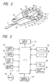
- An electronic circuit (described later) is built inside the hollow mounting part 11 and a display device 51, a power switch 52, a decision switch 53, a memory switch 54, and a start switch 55 are provided on the top surface of the hollow mounting part 11.
- the comparing color sample member 2 is a ring-shaped flat disc 22 having an engaged hole at the center.
- the ring-shaped flat disc 22 is rotatably fitted on the hollow mounting part 11 of the stationary disc 1.
- a plurality of windows 23 are formed in the outer peripheral portion of the flat disc 22 at equal angular intervals, and different color samples 24 are provided on the flat disc 22 at equal angular intervals in correspondence to the windows 23, respectively, in such a manner that the windows 23 are so positioned that, when the comparing color sample member 2 is mounted on the hollow mounting part 11, the test sheet 41 of the test stick 4 appears in a window 23.
- each of the color samples is rotatable into a position where it is adjacent the test sheet for a color comparison.
- the different color samples 42 have different colorations which are provided separately according to the different possible contents of sugar in urine; that is, colors meaning negative and positive signs are arranged in the form of a circle.
- Fig. 3 is a block diagram showing one example of the circuit which forms the test piece coloration comparative decision unit of the invention.
- the display device 51, the power switch 52, the decision switch 53, the memory switch 54, and the start switch 55 are provided on the top surface of the above-described hollow mounting part 11.
- a CPU (central processing unit) 56, a RAM (random access memory) 57, and ROM (read-only memory) 58, a timer 59, and a battery-low detector 50 are built inside the hollow mounting part 11.
- a control program executed by the CPU 56, described below and the mean values of the different color samples 24 are stored in the ROM 58.
- the mean values of the different color samples 24 are the numbers of the color samples 24 and the values (for instance urine sugar values) corresponding to the numbers which are stored in the form of a table.
- the RAM 57 is a non-volatile memory for storing the results of measurement (urine sugar values).
- the timer 59 starts counting the time required for performing the coloration comparative decision in response to the operation of the start switch 55, and operates a buzzer 62 providing an audible sound when a predetermined period of time has expired.
- the battery-low detector 60 detects whether or not the battery is serviceable, and, when the voltage of the battery is lower than a predetermined value, causes the display device 51 to display an indication of the same.
- the decision switch 53 is operated by the operator as follows: The operator visually compares the coloration of the test sheet 41 with the color samples 23, as each is moved into a position adjacent the test sheet 41 during rotation of color sample member 2, and when he determines that the test sheet 41 is equal, or substantially equal, to one of the color samples, the decision switch is operated to specify that the color sample 24 then adjacent the test sheet 41 is the closest in color to that of test sheet 41.
- a position detector 61 for instance a micro-switch, detects, during the rotation of the comparing color sample member 2, the angular positions of the different color samples 24.
- Protrusions are formed on the lower surface of the flat disc 22 in correspondence to the color samples 24, respectively, so that the micro-switch counts the protrusions passing through a reference position as the flat disc 22 bearing the color samples 24 is turned, thereby to detect the angular positions of the color samples 24.
- the color sample 24 then aligned with and adjacent to the test sheet 41 can be determined.
- different codes can be assigned to the different color samples 24, so that the color sample codes are optically read while the flat disc 22 is being turned, whereby, when the flat disc 22 is stopped and switch 53 is depressed, the color sample 24 aligned with the test sheet 41 is determined.
- the memory switch 54 is operated by the operator in order to read out previously determined and stored values (urine sugar values) which are read out of the RAM 57 and displayed on the display device 51.
- the CPU 56 reads the value (urine sugar value) corresponding to the color sample 24 thus determined out of the ROM 58, and displays it on the display device 51, and stores it in the RAM 57.
- Fig. 1 is a flow chart showing the operation of the test piece coloration comparative decision unit.
- step 2 the comparative decision unit is initialized (ST 2), and it is determined whether or not the battery is serviceable (ST 3). If the voltage of the battery is lower than a predetermined value, then in step ST 3 the result of decision is "Yes", and the low voltage of the battery is displayed on the display device 51 (ST 6). In this case, the measurement cannot be carried out (ST 7).
- step ST 3 the result of decision is "no"
- step ST 4 is executed, in which is it determined whether or not the memory switch 54 is depressed. That is, it is determined whether or not the operator has depressed the memory switch 54 to call and display the result of a previous measurement.
- the timer 59 is set to zero (ST 8), whereupon a time counting operation is started, and the time counted is displayed on the display device 51 (ST 11). That is, a work time (60 seconds) required for applying urine to the test sheet 41 and wiping the surplus of urine off the test sheet 41 is counted. During the work time, the time counted is incremented every second through ST 9 and ST 10, and is successively displayed (ST 11).
- step ST 12 When sixty (60) seconds has elapsed since the start of the timer, the result of decision in ST 12 becomes “Yes”, so that a buzzer is actuated to emit an audible sound telling the operator to place the test stick on the test stick mounting stand 33 (ST 14).
- step ST 13 it is detected whether or not 120 seconds has passed since the start of the timer; that is, the coloration comparative decision unit is placed in standby state for a period of time which is required for the color reaction of the test sheet 41.
- the buzzer again activated to emit an audible sound alerting the operator to compare the color of the test sheet 41 with the color samples 24 (ST 15).
- the operator evaluates the comparing color sample member 2 and visually compares the color of the test sheet 41 appearing successively in the windows 23 with the color samples provided adjacent to the windows 23 and thus successively adjacent to the test sheet; that is, he selects a color sample 24 which is most similar to the color of the test sheet 4, while rotating the comparing color sample member 2.
- step ST 16 it is determined whether or not the decision switch 53 has been depressed. When the decision switch 53 has been depressed, the result of determination in step ST 16 is "Yes", and the color samples 24 detected by the position detector is determined (ST 17).
- the value (urine sugar value) corresponding to the color sample thus determined is read out of the table in the ROM 58 (ST 18), and is then stored in the RAM 57 (ST 19). At the same time, the value thus read and stored is displayed in a digital mode on the display device 51 (ST 20).
- the memory switch 54 is depressed. As a result, the result of the decision in step ST 4 is "Yes", and the results of the color comparison measurements performed before and stored in the RAM 57 are displayed, in the order of storage, on the display device 51.
- the results (data values) of twenty prior measurements are stored and can be displayed. Therefore, after the result of the twentieth (20th) measurement has been displayed, the memory calling operation is ended (ST 25).
- the comparing color sample member having the windows in which the test sheet appears and the different color samples provided adjacent to the windows, respectively is rotatable, and the coloration of the test sheet viewed through the windows is visually compared with the different color samples so that a color sample equal or substantially similar to the coloration of the test sheet is selected, and the mean value of the color sample thus selected is read out of the memory and displayed on the display device. Therefore, a delicate color comparison can be achieved with high accuracy, and the mean value of the color sample thus selected can be automatically displayed on the display device.
- the color comparison is easier to perform and is more accurate than the operation of confirming the mean values of the color samples by using a numerical table. Furthermore, in the coloration comparative decision unit of the invention, unlike the electronic biochemical measuring device, instead of the reflection sensor, a visual comparison is employed for color comparison. Thus, the coloration comparative decision unit provided according to the invention allows an accurate determination of delicate color differences and is low in manufacturing cost and easily operated.
Landscapes
- Physics & Mathematics (AREA)
- Biochemistry (AREA)
- Health & Medical Sciences (AREA)
- Life Sciences & Earth Sciences (AREA)
- Chemical & Material Sciences (AREA)
- Analytical Chemistry (AREA)
- Spectroscopy & Molecular Physics (AREA)
- General Health & Medical Sciences (AREA)
- General Physics & Mathematics (AREA)
- Immunology (AREA)
- Pathology (AREA)
- Investigating Or Analysing Materials By The Use Of Chemical Reactions (AREA)
- Investigating Or Analysing Biological Materials (AREA)
- Spectrometry And Color Measurement (AREA)
Abstract
Description
- This invention relates to a unit for deciding the coloration of a test piece by comparison with reference samples. Such a unit is typically used for biochemical tests (such as a urine sugar test, a blood sugar test, or a urobilin test) and is hereinafter referred to as "a test piece coloration comparative decision unit", when applicable. More particularly, the invention relates to a test piece coloration comparative decision unit which is used for making a decision concerning the coloration of a test sheet (reagent part) impregnated, for instance, with urine which test sheet is then compared with a plurality of reference sample colors in order to determine sugar content in the urine.
- Heretofore, in a biochemical test for urine or the like, the coloration of a test sheet is determined by a non-electronic color comparative decision system in which an operator visually reads the coloration of the test sheet, or with an electronic urine sugar meter (an electronic biochemical measuring instrument) which comprises, for example a reflection sensor, for automatically reading and displaying the result of a test sheet coloration.
- Fig. 4 is a perspective view showing a conventional non-electronic test piece coloration comparative decision unit. It comprises: a
cylindrical case 72 with acap 71; and a sheet-shaped comparingcolor sample part 73 bonded to the cylindrical outer wall of thecase 72. A number of test sticks (each comprising a resin sheet, and atest sheet 75 impregnated with a reagent and bonded to one end of the resin sheet) 74 are accommodated in thecylindrical case 72. In a urine sugar test, thecap 71 is removed from thecylindrical case 72, and atest stick 74 is taken out of thecase 72. Then, thetest sheet 75 is impregnated with urine. Upon impregnation with urine, thetest sheet 75 shows a color reaction according to the content of sugar in the urine. The color of thetest sheet 75 thus treated is compared with various colors provided in the comparingcolor sample part 73 on thecylindrical case 72, for the purpose of deciding the coloration of the test sheet. That is, in thecolor sample part 73, various color samples (for negative and positive signs) 73a provided separately according to the content of sugar (grape sugar) in urine are arranged in a plurality of lines. The color of thetest sheet 75 thus treated is compared with the variety ofcolors 73a in thecolor sample part 73 in order to find the same color (or a color substantially similar thereto), whereby the coloration is determined. More specifically, it is determined whether the content of sugar in the urine is more or less than a standard (or negative or positive). - In an electronic biochemical measuring device, such as a urine sugar meter, a reflection sensor is used which includes a light emitting element and a light receiving element. In this device, light is applied to the coloration test sheet by the light emitting element (such as a light emitting diode), and light reflected from the test sheet is received by the light receiving element (such as a photo-transistor), so that the urine sugar value is automatically displayed in a digital mode according to the received color reaction light quantity.
- The first described, non-electronic, test piece coloration comparative decision unit is formed merely by bonding the sheet-shaped color sample part to the outer cylindrical wall of the test stick accommodating case (i.e., the cylindrical case). Therefore, for a color comparison, the test stick impregnated with the urine is held with the fingers and placed successively beside the various colors in the color sample part until the same color as the test sheet or a color similar that of the test sheet is found. That is, in the color comparison, the operator must incrementally move in fine steps the test sheet impregnated with the urine, i.e., the used test sheet, along the color sample part with a very small gap between the color sample part and the test sheet which requires considerable dexterity. Furthermore, in the color comparison, the test sheet is liable to shift from the color sample, and therefore it can be difficult for an operator to accurately decide the delicate color difference between various colors of the color sample part.
- In the electronic biochemical measuring unit (such as a urine sugar meter) the reflection sensor receives the color reaction light quantity of the test sheet, and the sugar value is automatically displayed according to the color reaction light quantity thus received. Therefore, with this device, the labor and time required for operation of the coloration comparative decision unit, and the operation of referring a mean value (urine sugar value) of a selected color to a comparison table to decide a color value (or a negative sign or positive sign) can be eliminated. However, the electronic biochemical measuring unit is disadvantageous in that, since it employs a reflection sensor, it is expensive, and is also sometimes difficult to accurately detect the delicate coloration of the test sheet with this device.
- A colorimeter according to the preamble of
claim 1 is known from US-A-2 058 073. - The invention is as defined in
claim 1. - The advantages and features of the invention will become more readily apparent from the following detailed description of the invention which is provided in connection with the accompanying drawings, in which:
- Fig. 1 is a flow chart illustrating the operation of an exemplary test piece coloration comparative decision unit according to this invention;
- Fig. 2 is a perspective view of the test piece coloration comparative decision unit according to the invention;
- Fig. 3 is a block diagram showing an electronic circuit provided for the test piece coloration comparative decision unit of the invention; and
- Fig. 4 is a perspective view showing a conventional coloration comparative decision unit.
- Fig. 2 is a perspective view showing one example of a test piece coloration comparative decision unit according to this invention.
- The coloration comparative decision unit comprises a
stationary disc 1 having a colored testpiece mounting stand 3; and a comparing color sample member 2 rotatably mounted on thestationary disc 1. - The
stationary disc 1 is in the form of a flat disc which has ahollow mounting part 11 protruding from the central portion of the disc, and the colored testpiece mounting stand 3 is in the form of a rectangular flat plate extending radially outwardly from a part of the periphery of thedisc 1. The junction of thestand 3 and thedisc 1 has anarcuate step 31 arranged along substantially a half of the circumference of thedisc 1. Thearcuate step 31 is formed because the colored test piece mounting stand is larger in thickness than thestationary disc 1. Thisarcuate step 31 contributes to the rotation of the comparing color sample part 2 (as described later). Agroove 32 substantially U-shaped in section is formed in the upper surface of the colored testpiece mounting stand 3 in such a manner that it is extended towards thehollow mounting part 11. The bottom of thegroove 32 thus formed is employed as a test stick mounting part (or a test piece mounting stand) 33. A test stick 4 (formed, for example, by bonding a reagent-impregnatedtest sheet 41 to one end portion of a resin sheet) is placed on the teststick mounting part 33. The base end of the teststick mounting part 33 merges with the colored testpiece mounting stand 3, while the top end thereof is adjacent to thestationary disc 1, but it is not connected to thestationary disc 1, whereby it can be elastically bent with the base end as the fulcrum; that is, it has an elastic restoring force. - The above-described
hollow mounting part 11 is in the form of a cylinder having a small height. An electronic circuit (described later) is built inside thehollow mounting part 11 and adisplay device 51, apower switch 52, adecision switch 53, amemory switch 54, and astart switch 55 are provided on the top surface of thehollow mounting part 11. - The comparing color sample member 2 is a ring-shaped flat disc 22 having an engaged hole at the center. The ring-shaped flat disc 22 is rotatably fitted on the
hollow mounting part 11 of thestationary disc 1. A plurality ofwindows 23 are formed in the outer peripheral portion of the flat disc 22 at equal angular intervals, anddifferent color samples 24 are provided on the flat disc 22 at equal angular intervals in correspondence to thewindows 23, respectively, in such a manner that thewindows 23 are so positioned that, when the comparing color sample member 2 is mounted on thehollow mounting part 11, thetest sheet 41 of thetest stick 4 appears in awindow 23. Thus, each of the color samples is rotatable into a position where it is adjacent the test sheet for a color comparison. The different color samples 42 have different colorations which are provided separately according to the different possible contents of sugar in urine; that is, colors meaning negative and positive signs are arranged in the form of a circle. - Fig. 3 is a block diagram showing one example of the circuit which forms the test piece coloration comparative decision unit of the invention.
- As was described above, the
display device 51, thepower switch 52, thedecision switch 53, thememory switch 54, and thestart switch 55 are provided on the top surface of the above-describedhollow mounting part 11. A CPU (central processing unit) 56, a RAM (random access memory) 57, and ROM (read-only memory) 58, atimer 59, and a battery-low detector 50 are built inside thehollow mounting part 11. - A control program executed by the
CPU 56, described below and the mean values of thedifferent color samples 24 are stored in theROM 58. The mean values of thedifferent color samples 24 are the numbers of thecolor samples 24 and the values (for instance urine sugar values) corresponding to the numbers which are stored in the form of a table. TheRAM 57 is a non-volatile memory for storing the results of measurement (urine sugar values). Thetimer 59 starts counting the time required for performing the coloration comparative decision in response to the operation of thestart switch 55, and operates abuzzer 62 providing an audible sound when a predetermined period of time has expired. The battery-low detector 60 detects whether or not the battery is serviceable, and, when the voltage of the battery is lower than a predetermined value, causes thedisplay device 51 to display an indication of the same. - The
decision switch 53 is operated by the operator as follows: The operator visually compares the coloration of thetest sheet 41 with thecolor samples 23, as each is moved into a position adjacent thetest sheet 41 during rotation of color sample member 2, and when he determines that thetest sheet 41 is equal, or substantially equal, to one of the color samples, the decision switch is operated to specify that thecolor sample 24 then adjacent thetest sheet 41 is the closest in color to that oftest sheet 41. Aposition detector 61, for instance a micro-switch, detects, during the rotation of the comparing color sample member 2, the angular positions of thedifferent color samples 24. Protrusions (not shown) are formed on the lower surface of the flat disc 22 in correspondence to thecolor samples 24, respectively, so that the micro-switch counts the protrusions passing through a reference position as the flat disc 22 bearing thecolor samples 24 is turned, thereby to detect the angular positions of thecolor samples 24. As a result, when the flat disc 22 is stopped, thecolor sample 24 then aligned with and adjacent to thetest sheet 41 can be determined. Instead of the micro-switch system described above, different codes can be assigned to thedifferent color samples 24, so that the color sample codes are optically read while the flat disc 22 is being turned, whereby, when the flat disc 22 is stopped andswitch 53 is depressed, thecolor sample 24 aligned with thetest sheet 41 is determined. - The
memory switch 54 is operated by the operator in order to read out previously determined and stored values (urine sugar values) which are read out of theRAM 57 and displayed on thedisplay device 51. - When the
position decision switch 54 is depressed and acolor sample 24 is selected and determined by theposition detector 61, theCPU 56 reads the value (urine sugar value) corresponding to thecolor sample 24 thus determined out of theROM 58, and displays it on thedisplay device 51, and stores it in theRAM 57. - Fig. 1 is a flow chart showing the operation of the test piece coloration comparative decision unit.
- When the operator turns on the power switch 52 ( in step 1 (hereinafter referred to as "ST", when applicable) the comparative decision unit is initialized (ST 2), and it is determined whether or not the battery is serviceable (ST 3). If the voltage of the battery is lower than a predetermined value, then in
step ST 3 the result of decision is "Yes", and the low voltage of the battery is displayed on the display device 51 (ST 6). In this case, the measurement cannot be carried out (ST 7). When the battery is serviceable, then instep ST 3 the result of decision is "no", the followingstep ST 4 is executed, in which is it determined whether or not thememory switch 54 is depressed. That is, it is determined whether or not the operator has depressed thememory switch 54 to call and display the result of a previous measurement. - When a new measurement is to be performed, i.e., the
memory switch 54 is not depressed, but thestart switch 55 is depressed, the result of the decision instep ST 4 is "No", and the result of decision in step ST 5 is "yes". Thus when thestart switch 55 is turned on, thetimer 59 is set to zero (ST 8), whereupon a time counting operation is started, and the time counted is displayed on the display device 51 (ST 11). That is, a work time (60 seconds) required for applying urine to thetest sheet 41 and wiping the surplus of urine off thetest sheet 41 is counted. During the work time, the time counted is incremented every second through ST 9 and ST 10, and is successively displayed (ST 11). When sixty (60) seconds has elapsed since the start of the timer, the result of decision in ST 12 becomes "Yes", so that a buzzer is actuated to emit an audible sound telling the operator to place the test stick on the test stick mounting stand 33 (ST 14). Under this condition, in step ST 13 it is detected whether or not 120 seconds has passed since the start of the timer; that is, the coloration comparative decision unit is placed in standby state for a period of time which is required for the color reaction of thetest sheet 41. When 120 seconds has passed, in step ST 13 the result of decision becomes "Yes", and the buzzer again activated to emit an audible sound alerting the operator to compare the color of thetest sheet 41 with the color samples 24 (ST 15). Under this condition, the operator evaluates the comparing color sample member 2 and visually compares the color of thetest sheet 41 appearing successively in thewindows 23 with the color samples provided adjacent to thewindows 23 and thus successively adjacent to the test sheet; that is, he selects acolor sample 24 which is most similar to the color of thetest sheet 4, while rotating the comparing color sample member 2. - Upon selection of one
color sample 24 in this manner, the operator stops the rotation of the comparing color sample member 2, and depresses thedecision switch 53. While the operator rotates the comparing color sample member 2 to find thecolor sample 24 which is equal or similar in color to thetest sheet 41, the position detector (micro-switch) 61 detects each of thedifferent color samples 24 which are moved by the rotation of the comparing color sample part. In step ST 16, it is determined whether or not thedecision switch 53 has been depressed. When thedecision switch 53 has been depressed, the result of determination in step ST 16 is "Yes", and thecolor samples 24 detected by the position detector is determined (ST 17). The value (urine sugar value) corresponding to the color sample thus determined is read out of the table in the ROM 58 (ST 18), and is then stored in the RAM 57 (ST 19). At the same time, the value thus read and stored is displayed in a digital mode on the display device 51 (ST 20). - When, after the above-described measurement has been repeatedly carried out, it is desired to confirm the results of past measurements, the
memory switch 54 is depressed. As a result, the result of the decision instep ST 4 is "Yes", and the results of the color comparison measurements performed before and stored in theRAM 57 are displayed, in the order of storage, on thedisplay device 51. In other words, upon the first depression of thememory switch 54, the result of the measurement stored firstly (n = 1) is selected (ST 21) and displayed on the display device 51 (ST 22); and upon the second depression thememory switch 54, the result of determination instep ST 23, in which it is determined whether or not the next memory is selected, become "Yes", so that the result of the measurement stored secondly (n = n + 1) is selected (ST 24) and displayed on thedisplay device 51; and so forth. In the above-described embodiment, the results (data values) of twenty prior measurements are stored and can be displayed. Therefore, after the result of the twentieth (20th) measurement has been displayed, the memory calling operation is ended (ST 25). - As described above, in the coloration comparative decision unit of the invention, the comparing color sample member having the windows in which the test sheet appears and the different color samples provided adjacent to the windows, respectively is rotatable, and the coloration of the test sheet viewed through the windows is visually compared with the different color samples so that a color sample equal or substantially similar to the coloration of the test sheet is selected, and the mean value of the color sample thus selected is read out of the memory and displayed on the display device. Therefore, a delicate color comparison can be achieved with high accuracy, and the mean value of the color sample thus selected can be automatically displayed on the display device.
- Accordingly, with the coloration comparative decision unit of the invention, the color comparison is easier to perform and is more accurate than the operation of confirming the mean values of the color samples by using a numerical table. Furthermore, in the coloration comparative decision unit of the invention, unlike the electronic biochemical measuring device, instead of the reflection sensor, a visual comparison is employed for color comparison. Thus, the coloration comparative decision unit provided according to the invention allows an accurate determination of delicate color differences and is low in manufacturing cost and easily operated.
- While the invention has been described and illustrated in connection with a preferred embodiment, it should be apparent that many modifications can be made without departing from the scope of the invention as defined by the appended claims. Accordingly, the invention is not limited by the foregoing description, but is only limited by the scope of the appended claims.
Claims (4)
- A colorimeter comprising means for generating an indication from a color output, a color chart having a plurality of reference colors, and means for locating the color chart with respect to the means for generating an indication, characterized in that the means for generating an indication comprises means for generating an electrical signal which corresponds to a favorable comparison of the color output to the reference colors on the color chart, the generating means generating the electrical signal corresponding to a favorable comparison in accordance with a selected location of the color chart with respect to the generating means.
- A colorimeter according to claim 1, the color output being the color on a reagent strip, the generating means generating said electrical signal when the color on the reagent strip approximates a color on the chart, the colorimeter further comprising display means connected to said generating means for displaying a reading corresponding to the electrical signal.
- A colorimeter according to claim 2 wherein the color chart comprises multiple color specimens to which a color of the reagent test strip can be compared, the means for generating an electrical signal comprises at least one electrical
switch providing a signal representative of said approximation and means for coupling said at least one electrical switch to the display means, said coupling means being responsive to state changes of said at least one switch to cause said display means to display the reading. - A colorimeter according to anyone of the preceding claims wherein the generating means produce respective electrical signals corresponding to each of said plurality of reference colors, and operator manipulable means are provided for causing said generating means to generate one of said electrical signals which is associated with a reference color deemed by an operator to compare favorably with the color of said color sample.
Applications Claiming Priority (3)
| Application Number | Priority Date | Filing Date | Title |
|---|---|---|---|
| JP187322/87 | 1987-07-27 | ||
| JP62187322A JPH07107507B2 (en) | 1987-07-27 | 1987-07-27 | Test item color comparison and judgment device |
| EP88112168A EP0301524B1 (en) | 1987-07-27 | 1988-07-27 | Test piece coloration comparative decision unit |
Related Parent Applications (2)
| Application Number | Title | Priority Date | Filing Date |
|---|---|---|---|
| EP88112168.5 Division | 1988-07-27 | ||
| EP88112168A Division EP0301524B1 (en) | 1987-07-27 | 1988-07-27 | Test piece coloration comparative decision unit |
Publications (3)
| Publication Number | Publication Date |
|---|---|
| EP0343692A2 EP0343692A2 (en) | 1989-11-29 |
| EP0343692A3 EP0343692A3 (en) | 1991-03-20 |
| EP0343692B1 true EP0343692B1 (en) | 1994-09-28 |
Family
ID=26114303
Family Applications (1)
| Application Number | Title | Priority Date | Filing Date |
|---|---|---|---|
| EP89111626A Expired - Lifetime EP0343692B1 (en) | 1987-07-27 | 1988-07-27 | Test piece coloration comparative decision unit |
Country Status (2)
| Country | Link |
|---|---|
| EP (1) | EP0343692B1 (en) |
| AT (1) | ATE82071T1 (en) |
Families Citing this family (1)
| Publication number | Priority date | Publication date | Assignee | Title |
|---|---|---|---|---|
| US4871258A (en) * | 1988-04-29 | 1989-10-03 | Boehringer Mannheim Corporation | Color test meter |
Family Cites Families (2)
| Publication number | Priority date | Publication date | Assignee | Title |
|---|---|---|---|---|
| US2058073A (en) * | 1935-05-23 | 1936-10-20 | Rare Chemicals Inc | Hemoglobinometer |
| JPH0737946B2 (en) * | 1983-08-05 | 1995-04-26 | 株式会社京都第一科学 | A device that measures body fluid components and stores and manages test data |
-
1988
- 1988-07-27 AT AT88112168T patent/ATE82071T1/en not_active IP Right Cessation
- 1988-07-27 EP EP89111626A patent/EP0343692B1/en not_active Expired - Lifetime
Also Published As
| Publication number | Publication date |
|---|---|
| ATE82071T1 (en) | 1992-11-15 |
| EP0343692A3 (en) | 1991-03-20 |
| EP0343692A2 (en) | 1989-11-29 |
Similar Documents
| Publication | Publication Date | Title |
|---|---|---|
| AU666621B2 (en) | Buttonless memory system for an electronic measurement device | |
| US5413764A (en) | Test carrier analysis system | |
| CA1315123C (en) | Color test meter | |
| EP0426967B1 (en) | Apparatus for measuring with light the concentration of a specimen | |
| EP0840122B1 (en) | Method and apparatus for calibrating a sensor element | |
| CA2455219A1 (en) | Calibration data entry system for a test instrument | |
| US4795613A (en) | Biochemical analyzer | |
| CS209419B2 (en) | Experimental set for determination of at least one chemical component in tested fluids | |
| EP0301524B1 (en) | Test piece coloration comparative decision unit | |
| JP4795580B2 (en) | Reagent management method and analyzer | |
| US5160980A (en) | Test piece coloration comparative decision unit | |
| EP0343692B1 (en) | Test piece coloration comparative decision unit | |
| CA1333012C (en) | Test piece coloration comparative decision unit | |
| US20080138906A1 (en) | Method for verifying fitness of an analysis element | |
| JPH08240594A (en) | Sampler system for chemical analyzer | |
| JP2739724B2 (en) | Specimen color comparison judge | |
| USRE34012E (en) | Biochemical analyzer | |
| JPH10123144A (en) | Method and apparatus for measuring quality control sample | |
| JPS6147565A (en) | Biochemical measuring apparatus | |
| JPS6168539A (en) | Biochemical measuring apparatus | |
| JP2534624Y2 (en) | Automatic analyzer | |
| JPS6148763A (en) | Biochemical measuring instrument | |
| JPS6141947A (en) | Biochemical measuring instrument | |
| JPS6318253A (en) | Biochemical measuring apparatus | |
| JPS6314899B2 (en) |
Legal Events
| Date | Code | Title | Description |
|---|---|---|---|
| PUAI | Public reference made under article 153(3) epc to a published international application that has entered the european phase |
Free format text: ORIGINAL CODE: 0009012 |
|
| 17P | Request for examination filed |
Effective date: 19890626 |
|
| AC | Divisional application: reference to earlier application |
Ref document number: 301524 Country of ref document: EP |
|
| AK | Designated contracting states |
Kind code of ref document: A2 Designated state(s): AT BE CH DE ES FR GB GR IT LI LU NL SE |
|
| RAP1 | Party data changed (applicant data changed or rights of an application transferred) |
Owner name: BOEHRINGER MANNHEIM CORPORATION |
|
| PUAL | Search report despatched |
Free format text: ORIGINAL CODE: 0009013 |
|
| AK | Designated contracting states |
Kind code of ref document: A3 Designated state(s): AT BE CH DE ES FR GB GR IT LI LU NL SE |
|
| 17Q | First examination report despatched |
Effective date: 19921202 |
|
| GRAA | (expected) grant |
Free format text: ORIGINAL CODE: 0009210 |
|
| AC | Divisional application: reference to earlier application |
Ref document number: 301524 Country of ref document: EP |
|
| AK | Designated contracting states |
Kind code of ref document: B1 Designated state(s): AT BE CH DE ES FR GB GR IT LI LU NL SE |
|
| PG25 | Lapsed in a contracting state [announced via postgrant information from national office to epo] |
Ref country code: LI Effective date: 19940928 Ref country code: BE Effective date: 19940928 Ref country code: CH Effective date: 19940928 Ref country code: NL Effective date: 19940928 Ref country code: AT Effective date: 19940928 Ref country code: GR Free format text: LAPSE BECAUSE OF FAILURE TO SUBMIT A TRANSLATION OF THE DESCRIPTION OR TO PAY THE FEE WITHIN THE PRESCRIBED TIME-LIMIT Effective date: 19940928 |
|
| REF | Corresponds to: |
Ref document number: 112390 Country of ref document: AT Date of ref document: 19941015 Kind code of ref document: T |
|
| REF | Corresponds to: |
Ref document number: 3851700 Country of ref document: DE Date of ref document: 19941103 |
|
| ITF | It: translation for a ep patent filed | ||
| ET | Fr: translation filed | ||
| REG | Reference to a national code |
Ref country code: ES Ref legal event code: FG2A Ref document number: 2061801 Country of ref document: ES Kind code of ref document: T3 |
|
| PG25 | Lapsed in a contracting state [announced via postgrant information from national office to epo] |
Ref country code: SE Effective date: 19941228 |
|
| REG | Reference to a national code |
Ref country code: CH Ref legal event code: PL |
|
| NLV1 | Nl: lapsed or annulled due to failure to fulfill the requirements of art. 29p and 29m of the patents act | ||
| PLBE | No opposition filed within time limit |
Free format text: ORIGINAL CODE: 0009261 |
|
| STAA | Information on the status of an ep patent application or granted ep patent |
Free format text: STATUS: NO OPPOSITION FILED WITHIN TIME LIMIT |
|
| PG25 | Lapsed in a contracting state [announced via postgrant information from national office to epo] |
Ref country code: LU Free format text: LAPSE BECAUSE OF NON-PAYMENT OF DUE FEES Effective date: 19950731 |
|
| 26N | No opposition filed | ||
| REG | Reference to a national code |
Ref country code: FR Ref legal event code: CD |
|
| REG | Reference to a national code |
Ref country code: GB Ref legal event code: IF02 |
|
| PGFP | Annual fee paid to national office [announced via postgrant information from national office to epo] |
Ref country code: ES Payment date: 20070710 Year of fee payment: 20 |
|
| PGFP | Annual fee paid to national office [announced via postgrant information from national office to epo] |
Ref country code: DE Payment date: 20070731 Year of fee payment: 20 |
|
| PGFP | Annual fee paid to national office [announced via postgrant information from national office to epo] |
Ref country code: GB Payment date: 20070618 Year of fee payment: 20 |
|
| PGFP | Annual fee paid to national office [announced via postgrant information from national office to epo] |
Ref country code: IT Payment date: 20070713 Year of fee payment: 20 |
|
| PGFP | Annual fee paid to national office [announced via postgrant information from national office to epo] |
Ref country code: FR Payment date: 20070706 Year of fee payment: 20 |
|
| REG | Reference to a national code |
Ref country code: GB Ref legal event code: PE20 Expiry date: 20080726 |
|
| REG | Reference to a national code |
Ref country code: ES Ref legal event code: FD2A Effective date: 20080728 |
|
| PG25 | Lapsed in a contracting state [announced via postgrant information from national office to epo] |
Ref country code: GB Free format text: LAPSE BECAUSE OF EXPIRATION OF PROTECTION Effective date: 20080726 |
|
| PG25 | Lapsed in a contracting state [announced via postgrant information from national office to epo] |
Ref country code: ES Free format text: LAPSE BECAUSE OF EXPIRATION OF PROTECTION Effective date: 20080728 |