EP0343612B1 - Method and devices for controlling the unloading of the items in an automatic sorting plant - Google Patents
Method and devices for controlling the unloading of the items in an automatic sorting plant Download PDFInfo
- Publication number
- EP0343612B1 EP0343612B1 EP89109294A EP89109294A EP0343612B1 EP 0343612 B1 EP0343612 B1 EP 0343612B1 EP 89109294 A EP89109294 A EP 89109294A EP 89109294 A EP89109294 A EP 89109294A EP 0343612 B1 EP0343612 B1 EP 0343612B1
- Authority
- EP
- European Patent Office
- Prior art keywords
- unloading
- belt
- speed
- unit
- items
- Prior art date
- Legal status (The legal status is an assumption and is not a legal conclusion. Google has not performed a legal analysis and makes no representation as to the accuracy of the status listed.)
- Expired - Lifetime
Links
- 238000000034 method Methods 0.000 title claims abstract description 24
- 230000001133 acceleration Effects 0.000 claims abstract description 12
- 230000001276 controlling effect Effects 0.000 claims 2
- 230000002596 correlated effect Effects 0.000 claims 1
- 230000004907 flux Effects 0.000 claims 1
- 238000010586 diagram Methods 0.000 description 6
- 241000360136 Megavirus bus Species 0.000 description 1
- 229910000828 alnico Inorganic materials 0.000 description 1
- 229910017052 cobalt Inorganic materials 0.000 description 1
- 239000010941 cobalt Substances 0.000 description 1
- GUTLYIVDDKVIGB-UHFFFAOYSA-N cobalt atom Chemical compound [Co] GUTLYIVDDKVIGB-UHFFFAOYSA-N 0.000 description 1
- 238000005094 computer simulation Methods 0.000 description 1
- 230000003111 delayed effect Effects 0.000 description 1
- 238000007599 discharging Methods 0.000 description 1
- 230000005415 magnetization Effects 0.000 description 1
- 230000010363 phase shift Effects 0.000 description 1
- 238000004088 simulation Methods 0.000 description 1
- 230000001360 synchronised effect Effects 0.000 description 1
Images


Classifications
-
- B—PERFORMING OPERATIONS; TRANSPORTING
- B65—CONVEYING; PACKING; STORING; HANDLING THIN OR FILAMENTARY MATERIAL
- B65G—TRANSPORT OR STORAGE DEVICES, e.g. CONVEYORS FOR LOADING OR TIPPING, SHOP CONVEYOR SYSTEMS OR PNEUMATIC TUBE CONVEYORS
- B65G43/00—Control devices, e.g. for safety, warning or fault-correcting
- B65G43/08—Control devices operated by article or material being fed, conveyed or discharged
-
- B—PERFORMING OPERATIONS; TRANSPORTING
- B65—CONVEYING; PACKING; STORING; HANDLING THIN OR FILAMENTARY MATERIAL
- B65G—TRANSPORT OR STORAGE DEVICES, e.g. CONVEYORS FOR LOADING OR TIPPING, SHOP CONVEYOR SYSTEMS OR PNEUMATIC TUBE CONVEYORS
- B65G17/00—Conveyors having an endless traction element, e.g. a chain, transmitting movement to a continuous or substantially-continuous load-carrying surface or to a series of individual load-carriers; Endless-chain conveyors in which the chains form the load-carrying surface
- B65G17/30—Details; Auxiliary devices
- B65G17/32—Individual load-carriers
- B65G17/34—Individual load-carriers having flat surfaces, e.g. platforms, grids, forks
- B65G17/345—Individual load-carriers having flat surfaces, e.g. platforms, grids, forks the surfaces being equipped with a conveyor
-
- B—PERFORMING OPERATIONS; TRANSPORTING
- B65—CONVEYING; PACKING; STORING; HANDLING THIN OR FILAMENTARY MATERIAL
- B65G—TRANSPORT OR STORAGE DEVICES, e.g. CONVEYORS FOR LOADING OR TIPPING, SHOP CONVEYOR SYSTEMS OR PNEUMATIC TUBE CONVEYORS
- B65G2201/00—Indexing codes relating to handling devices, e.g. conveyors, characterised by the type of product or load being conveyed or handled
- B65G2201/02—Articles
-
- B—PERFORMING OPERATIONS; TRANSPORTING
- B65—CONVEYING; PACKING; STORING; HANDLING THIN OR FILAMENTARY MATERIAL
- B65G—TRANSPORT OR STORAGE DEVICES, e.g. CONVEYORS FOR LOADING OR TIPPING, SHOP CONVEYOR SYSTEMS OR PNEUMATIC TUBE CONVEYORS
- B65G2207/00—Indexing codes relating to constructional details, configuration and additional features of a handling device, e.g. Conveyors
- B65G2207/18—Crossing conveyors
Definitions
- the invention relates to a method and relevant devices for controlling the unloading operations in sorting plants of the kind employed where considerable amount of items should be treated, e.g. in post offices, in mail order companies and the like.
- a standard plant of this type comprises a fixed path along which run a plurality of carriages or "units" on which the items to be sorted are laid; the latter are automatically unloaded when the relevant carriage passes before a determined collecting area when the item is being introduced in the apparatus, by means of computer controlled and actuated devices.
- the units are set in motion - according to methods known in the prior art - for instance by means of a continuous driving chain (when the path is substantially a rectilinear one) or by means of electric motors set on board of the units themselves and fed by power bars parallel to the path (when the path is a carrousel).
- the unloading is effected by means of movable belts that constitute the loading surface of the units.
- the unit belt is actuated by sending tension to the relevant motor by means of bus bars (different from the power bars and sectioned in correspondence of the unloading stations) in order to enable the drive control of the only belt-unit that is involved in the unloading.
- the unloading may take place at either side of the sorting path by simply reversing the sense of rotation of the belt, whose direction of rotation is perpendicular to the unit motion.
- GB-A-2 111 933 discloses a sorting plant comprising carriages, each provided with a rotatable belt which is actuated to discharge the carried items, in which the belt is rotated at a preselected unloading speed to discharge the item.
- the preamble of claims 1 and 5 are based on this document.
- An object of the present method is that of increasing the precision and the reliability of this kind of sorting plants in order to increase their precision during unloading.
- the invention method is the method according to claim 1.
- the invention plant is the plant according to claim 5.
- An embodiment of the invention method concerns the control of both the speed and the unloading trajectories in order to get all the items that are to be sorted to move as constantly as possible with respect to different speeds of the unit train.
- the items handled by a sorting plant have, to a certain extent, different sizes and masses.
- the prior art methods for discharging the items from the units do not take this into account, whether they are based on unloading by gravitational force, (e.g. tiltable plate units) nor when the unit has a loading surface consisting of a movable belt. These methods just synchronize unloading with the coding given to the item, making it necessary, thus, to employ collecting mouths greater than the traditionally used ones, in order to ensure that unloading takes place to the proper station.
- the unloading trajectories are controlled in function of the mass of the single items.
- What is requisite is to act upon the acceleration of the unit belt during unloading, so as to obtain a course of speed as constant as possible, from the condition where the item has minimum mass (referable to the smallest item) to the condition of the maximum allowed mass.
- the main advantages of this invention consist in the possibility of setting up contiguous and relatively small size unloading stations without this giving rise to any sorting errors and, consequently, to any hand rectification interventions.
- the control of the unloading trajectories may be described in this manner.
- roller 29 rotates along with the belt-unit, there occurs a variation in the magnetic flow produced by magnets 30, which is detected by the unit sensors 31.
- Hall sensors that, in function of the flow variation and therefore of the speed of the belt-unit, generate an electric signal that is sent to amplifier 32.
- drive control 14 controls the tension with which motor 11 should be fed to obtain a constant acceleration of belt 12 for all the unloaded articles.
- the belt would be somewhat hindered in its motion.
- Drive control 14 by means of amplifier 18 and feedback 15, would then increase the feeding tension of motor 11 until a correspondence between the signal of generator 17 and that of sensors 31 is reached.
- Fig. 1 are indicated, just by way of example, four Hall sensors arranged two by two, so as to have 16 impulses available for each complete revolution of the roller, and therefore an acceptable solution.
- Sensors 31 are arranged as to form a 45° angle, corresponding to a phase shift of 90° of the magnet-generated signals.
- the same magnets 30 are further employed to test the proper working of the belt-unit.
- the signal dected by sensor 33 is sent to device 34 that converts said signal, of impelling kind, into a signal that is function of the speed of the belt-unit.
- the speed value is sent from converter 34 to computer 3, that checks that said value correspond to determined parameters.
- Fig. 2 shows the trend of the belt acceleration in respect of three different working conditions.
- the data shared by the three curves are as follows: the belt actuation time (800 m/sec); the final speed of the belt (3.25 m/s); the instant when the items are being unloaded (after 300 m/sec from actuation).
- Curves A, B and C refer to the unit being unloaded, to the unit being loaded with 5 Kg. and to the unit being loaded with 10 Kg, respectively.
- the part of the curve comprised between 300 and 800 m/sec shows on the contrary a different trend in each single case; in fact, in the A condition the belt always revolves unloaded and therefore there is a constant increase in speed over 800 m/sec, whilst both in the B and in the C conditions the curves show a pitch after 300 m/sec, after the item has been unloaded and the belt runs without any load.
- Figgs. 3a and 3b show the unloading trajectories, respectively, of a small size item (5 cm side) and of an item whose sizes may be compared to those of the loading surface of the unit, trajectories that are obtained by a computer simulation of a real situation.
- Fig. 3c shows the trend of the trajectories in respect of a small size item that occupies two extreme positions on the unit.
- the acceleration value is equal to 14.8 m/s2 and the constant unloading trajectories make it possible to unload the item exaclty to the relative collecting station.
- Another advantage of the present method lies in the possibility of unloading the items even when the sorting plant does not work at rating speed.
- the units of the sorting plant are handled from the rest position to a working speed that is kept constant as the operations are being carried out. Said operations do not start until reaching the working speed, in the relatively short time of 15-20 sec. It may occur that, due to an emergency or a failure, the plant be deactivated after the units have been loaded and, once the emergency has ceased or the failure has been repaired, the plant be started again.
- the time necessary for recovering the working speed is equal to the already cited one, but in this case it is relatively long, as it is possible that the already loaded items reach in the meantime the unloading stations.
- the invention method makes it possible to actuate the unit belt in a variable manner, in function of the speed of the unit train. This is very important as a momentary stoppage of the plant does not involve any repetition of already effected operations, but the sorting precision and reliablity are ensured.
- Fig. 4 shows a unit 5 in the proximity of an unloading station 35 where item 1 should be unloaded. According to what above said, the unloading takes place by providing with tensions the bars 13, from which the belt-unit motor is fed through sliding contacts 36.
- the method according to the invention allows to carry out the unloading all the same, in the following way.
- the central computer 3 receives from main encoder 9 a seguence of impulses according to the unit speed, e.g. lower than the working speed.
- the computer compares then the speed value with the data inserted in its program and establishes that the motor of the belt-unit should be actuated by a certain delay.
- Said delay causes tension to be sent to bars 13, through the drive control 14, when unit 5, and therefore sliding contacts 36, are in a more advanced position that they are usually.
- this delayed actuation allows to obtain a predictable unloading trajectory and, accordingly, the unloading precision provided by the present method.
- Figgs. 5a-5c show the flow diagrams relevant to the main functions carried out by the sorting plant which is the subject of the present method.
- Fig. 5a refers to the main functions of the present method, namely the sequence of the loading, repositioning at the unit centre and unloading of the articles to be sorted, as well as the test for checking the proper working of the unit belts.
- the "automatic coding" diagram indicates the possibility of avoiding the coding operations carried out by the operator, which is otainable by providing the plant with an automatic code reader or scanner (e.g. post code or bar code) placed before the unloading area.
- an automatic code reader or scanner e.g. post code or bar code
- the scanner would automatically scan the destination of the items and would provide the central computer with the necessary data for the unloading.
- Fig. 5b refers to the control of the main encoder, and to the unloading stage of the items.
- the main encoder is handled by four main blocks, namely a main program, the control program for a proper working of the plant, the handling program and the encoder value computing program.
- the main encoder sorts the tasks to be carried out in function of the encoder value, and updates the item data on the suitable shift register.
- the "unit speed control" represents the computing of the unit speed each time the unloading should be actuated. At this stage the item is unloaded, by means of the impulses of a fictitious encoder, impulses derived from the main encoder in function of the unit speed.
- pointers By means of the pointers reset (a register or item data index that locates the unit that is to perform the unloading) and the data control (destination, weight and sizes) the item is unloaded by sending tension to the bars that feed the motor of the belt-unit.
- the main encoder deactivates the unloading device, resets the pointers and takes tension off the a.m. bus bars.
- Fig. 5c refers to the carrying out of the test on the proper working of units.
- the unit belt Under the control of the main encoder the unit belt is actuated, and the accurancy speed is feedback controlled.
- the thus tested unit is either enabled or disabled in function of the result of the previous control: actually, this means that a failure - if any - would cause the unit not to be utilized.
Landscapes
- Engineering & Computer Science (AREA)
- Mechanical Engineering (AREA)
- Branching, Merging, And Special Transfer Between Conveyors (AREA)
- Discharge Of Articles From Conveyors (AREA)
- Control Of Conveyors (AREA)
- Sorting Of Articles (AREA)
- Warehouses Or Storage Devices (AREA)
- Electrical Discharge Machining, Electrochemical Machining, And Combined Machining (AREA)
- Crystals, And After-Treatments Of Crystals (AREA)
Abstract
Description
- The invention relates to a method and relevant devices for controlling the unloading operations in sorting plants of the kind employed where considerable amount of items should be treated, e.g. in post offices, in mail order companies and the like.
- These are plants where the different functions are carried out and synchronized by a central computer that controls the course of the operations.
- A standard plant of this type comprises a fixed path along which run a plurality of carriages or "units" on which the items to be sorted are laid; the latter are automatically unloaded when the relevant carriage passes before a determined collecting area when the item is being introduced in the apparatus, by means of computer controlled and actuated devices.
- Plants of this kind are described in the following Italian patents and/or applications by the same Applicant:
Pat.No. 1 152 067; Pat.No. 1 151 648; Ut.Model No. 180 770; Applns. Nos. 22476 C/83, 21310 B/85, 24227 B/85, 25859 A/81, 21774 B/82, 23110 A/84, 22264 A/84 and 20779 A/85. Each item is coded by an operator and placed on the sorting circuit in loading stations the number of which varies in function of the amount of items to be sorted. - Along said circuit, that may develop according to various shapes and sizes, runs a train of units that occupy either the whole path or just a part thereof.
- The units are set in motion - according to methods known in the prior art - for instance by means of a continuous driving chain (when the path is substantially a rectilinear one) or by means of electric motors set on board of the units themselves and fed by power bars parallel to the path (when the path is a carrousel).
- The items, conveyed by the units, reach the collecting stations where they are unloaded. The unloading is effected by means of movable belts that constitute the loading surface of the units. At the moment of unloading, the unit belt is actuated by sending tension to the relevant motor by means of bus bars (different from the power bars and sectioned in correspondence of the unloading stations) in order to enable the drive control of the only belt-unit that is involved in the unloading.
- The unloading may take place at either side of the sorting path by simply reversing the sense of rotation of the belt, whose direction of rotation is perpendicular to the unit motion.
- GB-A-2 111 933 discloses a sorting plant comprising carriages, each provided with a rotatable belt which is actuated to discharge the carried items, in which the belt is rotated at a preselected unloading speed to discharge the item. The preamble of
claims 1 and 5 are based on this document. - An object of the present method is that of increasing the precision and the reliability of this kind of sorting plants in order to increase their precision during unloading.
- The invention method is the method according to
claim 1. The invention plant is the plant according to claim 5. - An embodiment of the invention method concerns the control of both the speed and the unloading trajectories in order to get all the items that are to be sorted to move as constantly as possible with respect to different speeds of the unit train.
- The invention will be now described in detail with reference to the following drawings, in which:
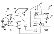
- Fig.1 is a block diagram of the actuating devices that enable the control of trajectories during unloading;
- Fig.2 shows the graphs of the acceleration to which the items are being subjected during unloading;
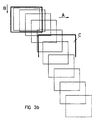
- Figgs. 3a-3c show the unloading trajectories of the items in the collecting stations;
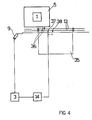
- Fig.4 is a block diagram of the drive control devices of the belt during unloading, in function of the machine speed;
- Figgs. 5a-5c show the flow diagrams relevant to the functions carried out according to the subject method.
- The items handled by a sorting plant have, to a certain extent, different sizes and masses. The prior art methods for discharging the items from the units do not take this into account, whether they are based on unloading by gravitational force, (e.g. tiltable plate units) nor when the unit has a loading surface consisting of a movable belt. These methods just synchronize unloading with the coding given to the item, making it necessary, thus, to employ collecting mouths greater than the traditionally used ones, in order to ensure that unloading takes place to the proper station.
- According to the present method, instead, the unloading trajectories are controlled in function of the mass of the single items.
- What is requisite is to act upon the acceleration of the unit belt during unloading, so as to obtain a course of speed as constant as possible, from the condition where the item has minimum mass (referable to the smallest item) to the condition of the maximum allowed mass.
- In fact, should the unit belt be subjected to the same acceleration apart from the mass it conveys, the unloading trajectories become constant and predictable, which is all the more significant if one considers that there are good chances for the item to arrive at the unloading zone at the centre of the unit.
- The main advantages of this invention consist in the possibility of setting up contiguous and relatively small size unloading stations without this giving rise to any sorting errors and, consequently, to any hand rectification interventions.
- It should be pointed out that during operation both the weight and the sizes of the items are detected, by known means, and the relevant data are sent to the computer that controls the whole apparatus.
- With reference to Fig. 1, the control of the unloading trajectories may be described in this manner. On the
roll 29, that represents the idle roller or the idler of the unit unloading belt, there are fourpermanent magnets 30, e.g. or the cobalt or alnico type, having a high magnetization degree. Said magnets are set along the periphery of the roller at 90° to each other, so that the magnetic polarities (N=north and S=south) alternate. - As
roller 29 rotates along with the belt-unit, there occurs a variation in the magnetic flow produced bymagnets 30, which is detected by theunit sensors 31. - These are, for instance, Hall sensors that, in function of the flow variation and therefore of the speed of the belt-unit, generate an electric signal that is sent to amplifier 32.
- From
amplifier 32 the signal is sent to thenode 16 ofdrive control 14, which node will compare said signal to that of theramp generator 17. - As happened during the transit of the item on the unit,
drive control 14 controls the tension with which motor 11 should be fed to obtain a constant acceleration ofbelt 12 for all the unloaded articles. - For instance, should the unit be carrying an item having a considerable mass, the belt would be somewhat hindered in its motion.
- At
node 16 would thus arrive a signal different than that ofgenerator 17, as belt 12 (and therefore roller 29) has a lower acceleration than that foreseeen. -
Drive control 14, by means ofamplifier 18 andfeedback 15, would then increase the feeding tension of motor 11 until a correspondence between the signal ofgenerator 17 and that ofsensors 31 is reached. - In Fig. 1 are indicated, just by way of example, four Hall sensors arranged two by two, so as to have 16 impulses available for each complete revolution of the roller, and therefore an acceptable solution.
-
Sensors 31, moreover, are arranged as to form a 45° angle, corresponding to a phase shift of 90° of the magnet-generated signals. - The
same magnets 30 are further employed to test the proper working of the belt-unit. - To this end, there is used another
Hall sensor 33, set on the ground near the path along which the units run. - The signal dected by
sensor 33 is sent todevice 34 that converts said signal, of impelling kind, into a signal that is function of the speed of the belt-unit. - The speed value is sent from
converter 34 tocomputer 3, that checks that said value correspond to determined parameters. - By this test it is possible to locate those units that, owing to a failure, are not in a position to carry out the unloading; they are left out of the sorting operations and subjected to repair. The same test also allows to set off an alarm in the case of an item being particularly heavy and not being unloaded: the belt-unit would tend to slip on the driven roller.
- As proof of the actual importance of the invention, Fig. 2 shows the trend of the belt acceleration in respect of three different working conditions.
- The curves of Fig. 2 were detected under real working conditions.
- The data shared by the three curves are as follows: the belt actuation time (800 m/sec); the final speed of the belt (3.25 m/s); the instant when the items are being unloaded (after 300 m/sec from actuation).
- The most significant part of the curve is therefore the one comprised in the initial 300 m/sec during which the unloading takes place.
Curves A, B and C refer to the unit being unloaded, to the unit being loaded with 5 Kg. and to the unit being loaded with 10 Kg, respectively. - By comparing the three curves over the first 300 m/sec, the increase in speed turns out to be the same in the three cases. It means that any item ranging between null mass and 10 Kg mass is subject to the same acceleration, which results in the discharge speed and trajectories being constant and therefore calculable with precision.
- The part of the curve comprised between 300 and 800 m/sec shows on the contrary a different trend in each single case; in fact, in the A condition the belt always revolves unloaded and therefore there is a constant increase in speed over 800 m/sec, whilst both in the B and in the C conditions the curves show a pitch after 300 m/sec, after the item has been unloaded and the belt runs without any load.
- Figgs. 3a and 3b show the unloading trajectories, respectively, of a small size item (5 cm side) and of an item whose sizes may be compared to those of the loading surface of the unit, trajectories that are obtained by a computer simulation of a real situation.
- In the same Figures are set out the details relating to the unloading simulation, the acceleration given by the belt-unit to the item being equal to 14.8 m/s², for either representation.
- The constant trend of the trajectories will be apparent if one considers (see Fig.3) that the largest size item seems not to get perfectly into the collecting station owing to the fact that the unit motion cannot be shown in the drawing.
- Fig. 3c shows the trend of the trajectories in respect of a small size item that occupies two extreme positions on the unit. In this case too the acceleration value is equal to 14.8 m/s² and the constant unloading trajectories make it possible to unload the item exaclty to the relative collecting station.
- As in Fig.3b, there is no evidence of the unit motion, which gives one the impression that the item on the left side of the unit would not get into the collecting mouth.
- Another advantage of the present method lies in the possibility of unloading the items even when the sorting plant does not work at rating speed.
- The units of the sorting plant are handled from the rest position to a working speed that is kept constant as the operations are being carried out. Said operations do not start until reaching the working speed, in the relatively short time of 15-20 sec. It may occur that, due to an emergency or a failure, the plant be deactivated after the units have been loaded and, once the emergency has ceased or the failure has been repaired, the plant be started again.
- The time necessary for recovering the working speed is equal to the already cited one, but in this case it is relatively long, as it is possible that the already loaded items reach in the meantime the unloading stations.
- It is thus necessary to bring the suspended operations to an end, without this affecting in the least the sorting precision.
According to the prior art, this drawback is usually obviated by discarding those items that reach the unloading stations before the plant works at normal speed rate. - The discarded items will then be put again in the sorting circuit following the customary loading operations.
- On the contrary, the invention method makes it possible to actuate the unit belt in a variable manner, in function of the speed of the unit train. This is very important as a momentary stoppage of the plant does not involve any repetition of already effected operations, but the sorting precision and reliablity are ensured.
- Fig. 4 shows a unit 5 in the proximity of an unloading
station 35 whereitem 1 should be unloaded. According to what above said, the unloading takes place by providing with tensions thebars 13, from which the belt-unit motor is fed through slidingcontacts 36. - When the unit speed is lower than the working speed (e.g. owing to a momentary stoppage) the method according to the invention allows to carry out the unloading all the same, in the following way.
- The
central computer 3 receives from main encoder 9 a seguence of impulses according to the unit speed, e.g. lower than the working speed. The computer compares then the speed value with the data inserted in its program and establishes that the motor of the belt-unit should be actuated by a certain delay. - Said delay causes tension to be sent to
bars 13, through thedrive control 14, when unit 5, and therefore slidingcontacts 36, are in a more advanced position that they are usually. - It ensues that, if at working speed conditions the
drive control 14 acts as the first slidingcontact 36 is in correspondence ofpoint 37, at lower speed conditions the same drive control will send tension tobars 13 when said sliding contact is in a more advanced position, e.g. at (point) 38. - In consideration of the lesser speed of the units, this delayed actuation allows to obtain a predictable unloading trajectory and, accordingly, the unloading precision provided by the present method.
- Figgs. 5a-5c show the flow diagrams relevant to the main functions carried out by the sorting plant which is the subject of the present method.
- Fig. 5a refers to the main functions of the present method, namely the sequence of the loading, repositioning at the unit centre and unloading of the articles to be sorted, as well as the test for checking the proper working of the unit belts.
- The "automatic coding" diagram indicates the possibility of avoiding the coding operations carried out by the operator, which is otainable by providing the plant with an automatic code reader or scanner (e.g. post code or bar code) placed before the unloading area.
- In this way the scanner would automatically scan the destination of the items and would provide the central computer with the necessary data for the unloading.
- Fig. 5b refers to the control of the main encoder, and to the unloading stage of the items.
- The main encoder is handled by four main blocks, namely a main program, the control program for a proper working of the plant, the handling program and the encoder value computing program.
- The main encoder, in turn, sorts the tasks to be carried out in function of the encoder value, and updates the item data on the suitable shift register. The "unit speed control" represents the computing of the unit speed each time the unloading should be actuated. At this stage the item is unloaded, by means of the impulses of a fictitious encoder, impulses derived from the main encoder in function of the unit speed.
- By means of the pointers reset (a register or item data index that locates the unit that is to perform the unloading) and the data control (destination, weight and sizes) the item is unloaded by sending tension to the bars that feed the motor of the belt-unit.
- Once the item has been unloaded, the main encoder deactivates the unloading device, resets the pointers and takes tension off the a.m. bus bars.
- Fig. 5c refers to the carrying out of the test on the proper working of units.
- Under the control of the main encoder the unit belt is actuated, and the accurancy speed is feedback controlled. The thus tested unit is either enabled or disabled in function of the result of the previous control: actually, this means that a failure - if any - would cause the unit not to be utilized.
- The operation ends as soon as the motor of the belt-unit has been turned off.
Claims (6)
- Method for controlling the unloading functions for the items to be sorted in sorting plants, said method being of the kind wherein the item to be sorted is placed on a carriage or unit that runs along a fixed path and is provided with a revolving belt (12) that moves orthogonally to the direction of feed at a controlled unloading speed in order to carry out the unloading, characterized by the fact that, during the unloading stage, one acts upon the acceleration imparted to the revolving belt, also called unit belt (12) in order to control the trajectory and the velocity of the unloaded items in function of their mass.
- Method according to claim 1, according to which the speed of rotation of the belt (12) is detected instant by instant through electric transductors; the signal generated by said transductors (30,31) is compared to a reference signal; and the feed of the motor means (11) that makes said belt rotate is conveniently acted upon.
- Method according to claim 1, characterized by the fact that the speed of rotation of the unloading belts is correlated with the forward speed of the units.
- A method according to claim 3, wherein the forward speed of the units is detected by a transductor capable of generating a sequence or electric impulses in function of said speed, and is then compared to pre-determined reference parameters, and wherein the feed of the drive motors (11) of the unit belts (12) is acted upon, on the basis of the obtained result, in order to adjust the unloading speed of the items to the forward speed of the units.
- A plant to carry out the method according to claims 1,2, characterized by a plurality of magnets (30) secured to one of the idlers of the unloading belt (12) as well as a plurality of sensors (31) secured to the unit and suitable to detect the variations in the magnetic flux following the rotation of said idler in order to generate an electric signal, means (32,14,17) for comparing said electric signal to a reference signal and for varying the feed of the drive motor (11) of the said unloading belt conveyor (12) as a function of the result of the comparison step, and means for acting upon the acceleration imparted to the unloading belt (12) in order to control the trajectory and the velocity of the unloaded items in function of their mass.
- A plant according to claim 5, characterized by the fact of providing a further sensor (33) for controlling the revolution of the support roller of the unloading belt.
Priority Applications (1)
| Application Number | Priority Date | Filing Date | Title |
|---|---|---|---|
| AT89109294T ATE103257T1 (en) | 1988-05-23 | 1989-05-23 | METHOD AND DEVICE FOR THE CONTROL OF OBJECTS UNLOADING IN AN AUTOMATIC SORTING DEVICE. |
Applications Claiming Priority (2)
| Application Number | Priority Date | Filing Date | Title |
|---|---|---|---|
| IT2069688 | 1988-05-23 | ||
| IT20696/88A IT1217695B (en) | 1988-05-23 | 1988-05-23 | METHOD AND DEVICES FOR THE CONTROL OF THE DISCHARGE FUNCTIONS OF THE OBJECTS IN AN AUTOMATIC SORTING SYSTEM |
Publications (3)
| Publication Number | Publication Date |
|---|---|
| EP0343612A2 EP0343612A2 (en) | 1989-11-29 |
| EP0343612A3 EP0343612A3 (en) | 1991-01-02 |
| EP0343612B1 true EP0343612B1 (en) | 1994-03-23 |
Family
ID=11170702
Family Applications (1)
| Application Number | Title | Priority Date | Filing Date |
|---|---|---|---|
| EP89109294A Expired - Lifetime EP0343612B1 (en) | 1988-05-23 | 1989-05-23 | Method and devices for controlling the unloading of the items in an automatic sorting plant |
Country Status (6)
| Country | Link |
|---|---|
| EP (1) | EP0343612B1 (en) |
| AT (1) | ATE103257T1 (en) |
| DE (1) | DE68914028T2 (en) |
| GB (1) | GB2218957B (en) |
| IT (1) | IT1217695B (en) |
| RU (1) | RU1833209C (en) |
Cited By (2)
| Publication number | Priority date | Publication date | Assignee | Title |
|---|---|---|---|---|
| EP0481341A1 (en) * | 1990-10-17 | 1992-04-22 | Francesco Canziani | Method for the control of a sorting apparatus |
| US5803230A (en) * | 1995-07-04 | 1998-09-08 | Sandvik Ab | Device for monitoring the movement of the loading/unloading belt of a transportation carriage, especially for sorting apparatuses |
Families Citing this family (4)
| Publication number | Priority date | Publication date | Assignee | Title |
|---|---|---|---|---|
| WO1997014636A1 (en) * | 1995-10-18 | 1997-04-24 | Sandvik Aktiebolag | Sorter mechanism |
| IT1276145B1 (en) | 1995-11-16 | 1997-10-27 | Cml Handling Technology S P A | SORTING EQUIPMENT WITH OBJECT TRANSPORT CELLS ON OVERLAYING SHELVES |
| IT1319594B1 (en) | 2000-12-20 | 2003-10-20 | Cml Handling Technology S P A | EQUIPMENT AND METHOD FOR THE ACTIVATION AND CONTROL OF THE SORTING UNIT IN A SORTING MACHINE |
| DE102008037261A1 (en) * | 2008-08-11 | 2010-02-25 | Siemens Aktiengesellschaft | System for piece goods sorting |
Family Cites Families (5)
| Publication number | Priority date | Publication date | Assignee | Title |
|---|---|---|---|---|
| GB1246794A (en) * | 1967-07-21 | 1971-09-22 | G D Peters & Co Ltd | Sorting apparatus |
| DE2909292C2 (en) * | 1979-03-09 | 1985-01-03 | Bernhard Beumer Maschinenfabrik Kg, 4720 Beckum | Feeding device for feeding individual piece goods onto a driven receiving conveyor |
| AT368711B (en) * | 1979-05-29 | 1982-11-10 | Kiener Konrad Dr | PLAYER FOR A GUIDED GAME PLAYABLE BY TWO PLAYERS |
| DK154478C (en) * | 1981-12-24 | 1989-06-12 | Francesco Canziani | DEVICE FOR TRANSPORTING AND READING SUBJECTS |
| IT1151648B (en) * | 1982-06-11 | 1986-12-24 | Francesco Canziani | FEEDING BENCH IN PARTICULAR FOR MACHINES FOR TRANSPORT AND SORTING OBJECTS |
-
1988
- 1988-05-23 IT IT20696/88A patent/IT1217695B/en active
- 1988-09-12 GB GB8821299A patent/GB2218957B/en not_active Expired - Lifetime
-
1989
- 1989-05-22 RU SU894614200A patent/RU1833209C/en active
- 1989-05-23 AT AT89109294T patent/ATE103257T1/en not_active IP Right Cessation
- 1989-05-23 EP EP89109294A patent/EP0343612B1/en not_active Expired - Lifetime
- 1989-05-23 DE DE68914028T patent/DE68914028T2/en not_active Expired - Fee Related
Cited By (2)
| Publication number | Priority date | Publication date | Assignee | Title |
|---|---|---|---|---|
| EP0481341A1 (en) * | 1990-10-17 | 1992-04-22 | Francesco Canziani | Method for the control of a sorting apparatus |
| US5803230A (en) * | 1995-07-04 | 1998-09-08 | Sandvik Ab | Device for monitoring the movement of the loading/unloading belt of a transportation carriage, especially for sorting apparatuses |
Also Published As
| Publication number | Publication date |
|---|---|
| GB2218957B (en) | 1992-10-21 |
| DE68914028T2 (en) | 1994-07-21 |
| EP0343612A2 (en) | 1989-11-29 |
| RU1833209C (en) | 1993-08-07 |
| DE68914028D1 (en) | 1994-04-28 |
| EP0343612A3 (en) | 1991-01-02 |
| IT8820696A0 (en) | 1988-05-23 |
| ATE103257T1 (en) | 1994-04-15 |
| GB2218957A (en) | 1989-11-29 |
| GB8821299D0 (en) | 1988-10-12 |
| IT1217695B (en) | 1990-03-30 |
Similar Documents
| Publication | Publication Date | Title |
|---|---|---|
| US3871511A (en) | Sorter system induction means | |
| EP0343613B1 (en) | Method for controlling the exact positioning of the items to be sorted in an automatic sorting plant | |
| US4938335A (en) | Method and devices for controlling the unloading of the items in an automatic sorting plant | |
| JP3833734B2 (en) | Parcel transport method and cross belt classification device | |
| US4331328A (en) | Controller for a servo driven document feeder | |
| US4653630A (en) | Method of and device for controlling the transfer of articles from a first conveyor belt to predetermined locations on a second conveyor belt | |
| US3719267A (en) | Apparatus for adjusting the speed of a transport band equipped with grippers to the speed of a conveyor band arranged ahead of such transport band | |
| JPS63123715A (en) | Light contact feeder | |
| GB2144698A (en) | A method for feeding articles to an apparatus with the articles presented according to a predetermined angular disposition, and apparatus for carrying out said method | |
| HUP0002875A2 (en) | Powder coating apparatus | |
| EP0343612B1 (en) | Method and devices for controlling the unloading of the items in an automatic sorting plant | |
| GB2111933A (en) | Unloading means for conveying apparatus | |
| EP0752381B1 (en) | Device for monitoring the movement of the loading/unloading belt of a transportation carriage, especially for sorting apparatuses | |
| EP0556866A3 (en) | Sorting apparatus | |
| KR910000416A (en) | Carrier using linear motor | |
| EP0261619B1 (en) | Method for the controlled actuation of devices for unloading the conveyed items, in sorting apparatus | |
| GB1365554A (en) | Method of feeding discrete articles from a first work station to a second work station and a system therefor | |
| US4180153A (en) | High speed batch counting apparatus | |
| JPH06127659A (en) | Transferring equipment | |
| CN109625823B (en) | Feeding system and speed monitoring method thereof | |
| JPS5656414A (en) | Method of adjusting charging section of automatic parcel classifying system and device for executing said method | |
| ATE184854T1 (en) | DEVICE AND METHOD FOR PROMOTING INDIVIDUAL ITEMS | |
| US3935940A (en) | Sorter system induction means | |
| IT1240627B (en) | Apparatus for singularising objects | |
| SE9404444L (en) | Method and apparatus for sorting containers |
Legal Events
| Date | Code | Title | Description |
|---|---|---|---|
| PUAI | Public reference made under article 153(3) epc to a published international application that has entered the european phase |
Free format text: ORIGINAL CODE: 0009012 |
|
| AK | Designated contracting states |
Kind code of ref document: A2 Designated state(s): AT BE CH DE ES FR GR LI LU NL SE |
|
| 17P | Request for examination filed |
Effective date: 19900406 |
|
| PUAL | Search report despatched |
Free format text: ORIGINAL CODE: 0009013 |
|
| AK | Designated contracting states |
Kind code of ref document: A3 Designated state(s): AT BE CH DE ES FR GR LI LU NL SE |
|
| RHK1 | Main classification (correction) |
Ipc: B65G 17/34 |
|
| 17Q | First examination report despatched |
Effective date: 19920811 |
|
| GRAA | (expected) grant |
Free format text: ORIGINAL CODE: 0009210 |
|
| AK | Designated contracting states |
Kind code of ref document: B1 Designated state(s): AT BE CH DE ES FR GR LI LU NL SE |
|
| PG25 | Lapsed in a contracting state [announced via postgrant information from national office to epo] |
Ref country code: SE Free format text: THE PATENT HAS BEEN ANNULLED BY A DECISION OF A NATIONAL AUTHORITY Effective date: 19940323 Ref country code: GR Free format text: LAPSE BECAUSE OF FAILURE TO SUBMIT A TRANSLATION OF THE DESCRIPTION OR TO PAY THE FEE WITHIN THE PRESCRIBED TIME-LIMIT Effective date: 19940323 Ref country code: ES Free format text: THE PATENT HAS BEEN ANNULLED BY A DECISION OF A NATIONAL AUTHORITY Effective date: 19940323 Ref country code: BE Effective date: 19940323 Ref country code: AT Effective date: 19940323 |
|
| REF | Corresponds to: |
Ref document number: 103257 Country of ref document: AT Date of ref document: 19940415 Kind code of ref document: T |
|
| REF | Corresponds to: |
Ref document number: 68914028 Country of ref document: DE Date of ref document: 19940428 |
|
| PG25 | Lapsed in a contracting state [announced via postgrant information from national office to epo] |
Ref country code: LU Free format text: LAPSE BECAUSE OF NON-PAYMENT OF DUE FEES Effective date: 19940531 |
|
| ET | Fr: translation filed | ||
| PLBE | No opposition filed within time limit |
Free format text: ORIGINAL CODE: 0009261 |
|
| STAA | Information on the status of an ep patent application or granted ep patent |
Free format text: STATUS: NO OPPOSITION FILED WITHIN TIME LIMIT |
|
| 26N | No opposition filed | ||
| PGFP | Annual fee paid to national office [announced via postgrant information from national office to epo] |
Ref country code: FR Payment date: 19990511 Year of fee payment: 11 |
|
| PGFP | Annual fee paid to national office [announced via postgrant information from national office to epo] |
Ref country code: DE Payment date: 19990525 Year of fee payment: 11 |
|
| PGFP | Annual fee paid to national office [announced via postgrant information from national office to epo] |
Ref country code: CH Payment date: 19990526 Year of fee payment: 11 |
|
| PGFP | Annual fee paid to national office [announced via postgrant information from national office to epo] |
Ref country code: NL Payment date: 19990531 Year of fee payment: 11 |
|
| PG25 | Lapsed in a contracting state [announced via postgrant information from national office to epo] |
Ref country code: LI Free format text: LAPSE BECAUSE OF NON-PAYMENT OF DUE FEES Effective date: 20000531 Ref country code: CH Free format text: LAPSE BECAUSE OF NON-PAYMENT OF DUE FEES Effective date: 20000531 |
|
| PG25 | Lapsed in a contracting state [announced via postgrant information from national office to epo] |
Ref country code: NL Free format text: LAPSE BECAUSE OF NON-PAYMENT OF DUE FEES Effective date: 20001201 |
|
| REG | Reference to a national code |
Ref country code: CH Ref legal event code: PL |
|
| PG25 | Lapsed in a contracting state [announced via postgrant information from national office to epo] |
Ref country code: FR Free format text: LAPSE BECAUSE OF NON-PAYMENT OF DUE FEES Effective date: 20010131 |
|
| NLV4 | Nl: lapsed or anulled due to non-payment of the annual fee |
Effective date: 20001201 |
|
| PG25 | Lapsed in a contracting state [announced via postgrant information from national office to epo] |
Ref country code: DE Free format text: LAPSE BECAUSE OF NON-PAYMENT OF DUE FEES Effective date: 20010301 |
|
| REG | Reference to a national code |
Ref country code: FR Ref legal event code: ST |