EP0343601A2 - Apparatus for producing tube - Google Patents
Apparatus for producing tube Download PDFInfo
- Publication number
- EP0343601A2 EP0343601A2 EP89109281A EP89109281A EP0343601A2 EP 0343601 A2 EP0343601 A2 EP 0343601A2 EP 89109281 A EP89109281 A EP 89109281A EP 89109281 A EP89109281 A EP 89109281A EP 0343601 A2 EP0343601 A2 EP 0343601A2
- Authority
- EP
- European Patent Office
- Prior art keywords
- tube
- mandrel
- tape
- rotating
- drawing device
- Prior art date
- Legal status (The legal status is an assumption and is not a legal conclusion. Google has not performed a legal analysis and makes no representation as to the accuracy of the status listed.)
- Granted
Links
- 238000004804 winding Methods 0.000 claims abstract description 28
- 229920005989 resin Polymers 0.000 claims abstract description 13
- 239000011347 resin Substances 0.000 claims abstract description 13
- 238000001035 drying Methods 0.000 claims abstract description 6
- 238000004519 manufacturing process Methods 0.000 description 27
- 230000000712 assembly Effects 0.000 description 10
- 238000000429 assembly Methods 0.000 description 10
- 230000033001 locomotion Effects 0.000 description 5
- 238000011144 upstream manufacturing Methods 0.000 description 3
- 229920006311 Urethane elastomer Polymers 0.000 description 2
- 239000011248 coating agent Substances 0.000 description 2
- 238000000576 coating method Methods 0.000 description 2
- 239000004745 nonwoven fabric Substances 0.000 description 2
- 238000013459 approach Methods 0.000 description 1
- 230000005540 biological transmission Effects 0.000 description 1
- 230000001419 dependent effect Effects 0.000 description 1
- 229920001971 elastomer Polymers 0.000 description 1
- 239000012530 fluid Substances 0.000 description 1
- 239000003292 glue Substances 0.000 description 1
- 239000000463 material Substances 0.000 description 1
- 238000012986 modification Methods 0.000 description 1
- 230000004048 modification Effects 0.000 description 1
- 239000012188 paraffin wax Substances 0.000 description 1
- 230000002093 peripheral effect Effects 0.000 description 1
- 238000009877 rendering Methods 0.000 description 1
- 229920003002 synthetic resin Polymers 0.000 description 1
- 239000000057 synthetic resin Substances 0.000 description 1
- 238000011282 treatment Methods 0.000 description 1
Images


Classifications
-
- B—PERFORMING OPERATIONS; TRANSPORTING
- B65—CONVEYING; PACKING; STORING; HANDLING THIN OR FILAMENTARY MATERIAL
- B65H—HANDLING THIN OR FILAMENTARY MATERIAL, e.g. SHEETS, WEBS, CABLES
- B65H45/00—Folding thin material
-
- B—PERFORMING OPERATIONS; TRANSPORTING
- B29—WORKING OF PLASTICS; WORKING OF SUBSTANCES IN A PLASTIC STATE IN GENERAL
- B29C—SHAPING OR JOINING OF PLASTICS; SHAPING OF MATERIAL IN A PLASTIC STATE, NOT OTHERWISE PROVIDED FOR; AFTER-TREATMENT OF THE SHAPED PRODUCTS, e.g. REPAIRING
- B29C31/00—Handling, e.g. feeding of the material to be shaped, storage of plastics material before moulding; Automation, i.e. automated handling lines in plastics processing plants, e.g. using manipulators or robots
- B29C31/002—Handling tubes, e.g. transferring between shaping stations, loading on mandrels
-
- B—PERFORMING OPERATIONS; TRANSPORTING
- B29—WORKING OF PLASTICS; WORKING OF SUBSTANCES IN A PLASTIC STATE IN GENERAL
- B29C—SHAPING OR JOINING OF PLASTICS; SHAPING OF MATERIAL IN A PLASTIC STATE, NOT OTHERWISE PROVIDED FOR; AFTER-TREATMENT OF THE SHAPED PRODUCTS, e.g. REPAIRING
- B29C53/00—Shaping by bending, folding, twisting, straightening or flattening; Apparatus therefor
- B29C53/56—Winding and joining, e.g. winding spirally
- B29C53/58—Winding and joining, e.g. winding spirally helically
- B29C53/60—Winding and joining, e.g. winding spirally helically using internal forming surfaces, e.g. mandrels
- B29C53/607—Winding and joining, e.g. winding spirally helically using internal forming surfaces, e.g. mandrels having driving means for advancing the wound articles, e.g. belts, rolls
-
- B—PERFORMING OPERATIONS; TRANSPORTING
- B31—MAKING ARTICLES OF PAPER, CARDBOARD OR MATERIAL WORKED IN A MANNER ANALOGOUS TO PAPER; WORKING PAPER, CARDBOARD OR MATERIAL WORKED IN A MANNER ANALOGOUS TO PAPER
- B31C—MAKING WOUND ARTICLES, e.g. WOUND TUBES, OF PAPER, CARDBOARD OR MATERIAL WORKED IN A MANNER ANALOGOUS TO PAPER
- B31C3/00—Making tubes or pipes by feeding obliquely to the winding mandrel centre line
-
- B—PERFORMING OPERATIONS; TRANSPORTING
- B29—WORKING OF PLASTICS; WORKING OF SUBSTANCES IN A PLASTIC STATE IN GENERAL
- B29C—SHAPING OR JOINING OF PLASTICS; SHAPING OF MATERIAL IN A PLASTIC STATE, NOT OTHERWISE PROVIDED FOR; AFTER-TREATMENT OF THE SHAPED PRODUCTS, e.g. REPAIRING
- B29C2793/00—Shaping techniques involving a cutting or machining operation
- B29C2793/009—Shaping techniques involving a cutting or machining operation after shaping
-
- B—PERFORMING OPERATIONS; TRANSPORTING
- B29—WORKING OF PLASTICS; WORKING OF SUBSTANCES IN A PLASTIC STATE IN GENERAL
- B29K—INDEXING SCHEME ASSOCIATED WITH SUBCLASSES B29B, B29C OR B29D, RELATING TO MOULDING MATERIALS OR TO MATERIALS FOR MOULDS, REINFORCEMENTS, FILLERS OR PREFORMED PARTS, e.g. INSERTS
- B29K2711/00—Use of natural products or their composites, not provided for in groups B29K2601/00 - B29K2709/00, for preformed parts, e.g. for inserts
- B29K2711/12—Paper, e.g. cardboard
Definitions
- the present invention relates to an apparatus for producing a tube by helically winding tape on a mandrel.
- Cores or paper tubes are produced generally by helically winding paper tape in layers around a mandrel in the form of a round rod to form a tubular body and continuously delivering the tubular body from the forward end of the mandrel.
- Two-pulley and three-pulley devices shown in Figs. 12 and 13, respectively, are conventionally used for winding paper tape around the mandrel.
- the tape winding device 2 shown in Fig. 12 has two rotatable pulleys 13, 13 arranged on opposite sides of a mandrel 12.
- a belt 29 obliquely wound on the mandrel 12 by one turn is endlessly reeved around the two pulleys 13, 13.
- the tape winding three-pulley device 2 shown in Fig. 13 comprises one main rotatable pulley 13 disposed on one side of a mandrel 12, and first and second two auxiliary rotatable pulleys 13a, 13b arranged on the other side of the mandrel.
- a first belt 29 is endlessly reeved around the upper portion of the main pulley 13 and the first auxiliary pulley 13a
- a second belt 29a is endlessly wound around the lower portion of the main pulley 13 and the second auxiliary pulley 13b.
- the first and second belts 29, 29a are wound on the mandrel 12 by one turn symmetrically.
- paper tapes 91a, 91b paid off from two tape feeders 90, 90, respectively are engaged between the mandrel 12 and the belt 29 or belts 29, 29a driven by the pulleys and helically wound on the mandrel 12 into a paper tube 92 while being slipped on the mandrel by the friction between the tape and the belt.
- the belt or belts function to wind the paper tapes around the mandrel and also to forward the paper tube axially thereof.
- paper tubes have a small diameter, medium wall thickness or large wall thickness
- those for a particular use are required of very high pressure resistance.
- the paper tape must be subjected to great back tension and tightly wound on the mandrel. Nevertheless, if the belt wound on the mandrel by one turn is driven to wind the paper tape around the mandrel and also to forward the resulting paper tube as in the conventional practice, slippage is likely to occur between the paper tube and the tape, whereas increased back tension on the paper tape permits slippage of the belt. Since the torque of the pulley is transmitted to the tape by virtue of the friction between the pulley and the belt and also the friction between the belt and the tape, the power transmission efficiency is low. Consequently, even if an increased torque is given to the pulley, difficulty is encountered in winding the highly tensioned tape around the mandrel helically continuously. Thus, it is difficult to produce paper tubes having the desired pressure resistance.
- the belt acts to advance axially of the mandrel at the portion thereof around the mandrel, while the tension on the belt retracts the belt axially of the mandrel. Since this motion is repeated, the belt is always reciprocatingly moved over a small distance axially of the mandrel. Because the paper tape is wound on the mandrel by the belt reciprocatingly moving in this fashion, a clearance is liable to occur between the adjacent two portions of the tape wound on the mandrel. Such a clearance not only impairs the strength of the paper tube but also varies the speed of axial transport of the tube.
- the tube Before the paper tube is made into a finished product, the tube is not infrequently subjected to aftertreatments such as coating of the tube surface with resin and grinding of the resulting surface.
- the conventional machine for producing paper tubes is low in its force to deliver the paper tube axially thereof, so that such aftertreatments offer increased resistance to the axial movement of the tube to result in variations in the speed of axial movement of the tube and make the tube production speed unstable, if the treatments are conducted in sequence by devices connected to the production line downstream from the machine. Consequently, the aftertreatment devices are not in smooth operative relation with the machine, failing to produce products of good quality. With the conventional device, therefore, the paper tube is cut to a specified length, and the cut tube is then treated as required by another processing line, hence a poor production efficiency.
- the main object of the present invention is to provide an apparatus for producing a paper tube or like tube at a constant speed which apparatus is adapted to deliver the tube axially thereof with a great force while rotating the tube without warping the mandrel so that tape can be helically wound on the mandrel tightly with a great torsional force without creating any tape-to-tape clearance.
- the present inven strictlytion provides an apparatus for producing a tube which comprises a tube rotating-drawing device in place of or in addition to a conventional tape winding device.
- the tube rotating-drawing device comprises a rotary frame coupled to rotary drive means and rotatable in a fixed position around a mandrel, support members provided on the rotary frame with the mandrel positioned between the support members and movable toward or away from the mandrel, means for pressing the support members against the mandrel, and a delivery assembly mounted on each of the support members and having a delivery member coupled to delivery drive means and movable along an endless path or rotatable in a plane containing the axis of the mandrel for delivering the tube formed on the mandrel axially thereof by frictional contact of the delivery member with the tube on the mandrel.
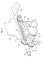
- the paper tube production apparatus of the invention comprises a mandrel 12 horizontally disposed on a base 1 and fixed at its one end to the base, a pair of paper tape feeders 90, 90 arranged at the respective sides of the base 1, and a tube rotating-drawing device 3.
- Fig. 1A shows an example of paper tube production line including various devices, i.e., a tube press 54 and a tape winding device 2 which are arranged upstream from the tube rotating-drawing device 3; and a resin-coated tape feeder 93, resin applicator stand 94, drying oven 95, grinding stand 96, tube cutter 97 and tube support 98 which are arranged downstream from the tube rotating-drawing device 3.
- Such components can be selected as desired for use in combination with the paper tube production apparatus of Fig. 1.
- front and rear refer respectively to the downstream side and the upstream side of the production line.
- the mandrel 12 extends horizontally toward the front and is supported by a bracket 11 at the rear end of the base 1. The front end of the mandrel is left unsupported.
- Paper tape feed means preferably comprises two feeders, i.e., the above-mentioned tape feeders 90, 90 which are arranged at the respective sides of the base 1.
- a paper tube 91a for forming the lowemost layer of a core or paper tube 92 is obliquely fed to the mandrel 12 from one of the feeders 90.
- the paper tape 91a is coated on the rear surface thereof with paraffin to reduce the friction between the tape and the mandrel 12.
- a plurality of paper tapes 91b lapping over one another at the side edge are fed obliquely to the mandrel 12 from the other feeder 90.
- a glue is applied to the rear surface of each tape 91b by an applicator 99.
- the number of tape feeders is not limited to two but the tapes 91a, 91b can be supplied from a single feeder, or three or more feeders.
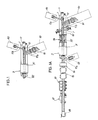
- the tube rotating-drawing device 3 has a fixed frame 31 in the form of a hollow cylinder and mounted horizontally on the base 1 concentrically with the mandrel 12.
- the mandrel 12 extends through a boss 33a on a rear end plate 33, with a clearance formed around the mandrel, and has its front end positioned close to a boss 32a on a front end plate 32.
- a rotary frame 34 in the form of a hollow cylinder is housed in the fixed frame 31 rotatably and concentrically with the mandrel 12.
- Central bosses 35a, 36a on opposite end plates 35, 36 of the rotary frame 34 are rotatably supported by bearings 37, 37 on the bosses 32a, 33a of the fixed frame 31.
- the rotary frame 34 is free to rotate within the fixed frame 31.
- Rotary drive means 4 mounted on the fixed frame 31 is coupled to the rotary frame 34 to drivingly rotate the frame 34.
- the drive means 4 includes a shaft 41 rotatably extending through the front end plate 32 of the fixed frame 31 and coupled at its outer end to a motor 45 by a chain 44.
- a pinion 42 is mounted on the inner end of the shaft 41.
- the motor 45 and a motor 26 (Fig. 6) for the tape winding device 2 are coupled to a rotation control unit (not shown) of the inverter type, whereby the speed of rotation of the rotary frame 34 is variable in accordance with the speed of travel of a belt 29 of the tape winding device 2.
- a pair of support members 100, 100 are opposed to each other inside the rotary frame 34, with the mandrel 12 interposed therebetween.
- Each support member 100 is slidably supported as held between a pair of guide plates 101, 101 secured to the inner surface of the rotary frame 34 and is movable forward and rearward, and also toward or away from the mandrel 12.
- the support member 100 is supported at its front and rear portions by parallel levers 102, 102 on the rotary frame 34 forwardly and rearwardly movably.
- pressing means 6 is connected to an intermediate portion of the support member 100 for pressing the support member against the mandrel 12.
- the pressing means 6 includes toggle links 61, 62 respectively pivoted to the support member 100 and a bracket 60 mounted on the inner surface of the rotary frame 34, and a push rod 63 disposed in parallel to the mandrel 12 and pivoted to the connection between the two links 61, 62.
- the push rod 63 slidably extends through the rear end plate 36 of the rotary frame 34 and is revolvably connected to a cylinder assembly 64 mounted on the boss 33a of the fixed frame 31.
- the rod 63 is movable forward or rearward.
- the cylinder assembly 64 comprises a short cylinder 65 secured to the end plate 33 of the fixed frame 31 and surrounding the boss 33a concentrically therewith, and an annular piston 66 slidably provided between the boss 33a and the cylinder 65.
- a slidable tubular piston rod 67 fitted around the boss 33a extends from the piston 66 forward beyond the front end of the cylinder 65 and is formed with a circumferential groove 68 at its front end.
- the push rod 63 is connected to a ring plate 69 rotatably fitted in the groove 68.
- a pressure fluid when supplied to the cylinder assembly 64, advances the piston rod 67, which in turn pushes the push rods 63 forward, causing the toggle links to forcibly press the support members 100 against the mandrel 12.
- each support member 100 approaches the mandrel 12 while slightly advancing axially of the mandrel 12.
- the ring plate 69 connecting the push rods 63 to the cylinder assembly 64 is rotatably engaged in the circumferential groove 68 in the piston rod 67 of the assembly 64, so that the push rods 63 are movable around the mandrel 12 with the rotary frame 34 by the rotation of this frame 34 and can also be pushed forward by the piston rod 67.
- the paper tapes 91a, 91b wound on the mandrel 12 and brought into the rotary frame 34 are withdrawn therefrom axially of the mandrel 12 by a delivery assembly 7 mounted on each support member 100, in pressing contact with the tapes.
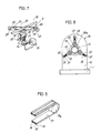
- the delivery assembly 7 of the present embodiment comprises a pair of timing pulleys 71, 72 supported respectively at the front and rear ends of the support member 100, and a timing belt 73 endlessly reeved around the two pulleys.
- urethane rubber lips 74, 74 are attached to the outer surface of the timing belt 73 along the respective side edges thereof over the entire circumference of the belt, and a furrow 75 formed between the lips 74, 74 extends over the entire circumference.
- the timing belt 73 serves as a member for delivering the paper tube axially thereof.
- a plurality of auxiliary rollers 76 are closely arranged between the two timing pulleys 71, 72 and rotatably mounted on the support member 100. Where the timing belt 73 faces the mandrel 12, the auxiliary rollers 76 are in contact with the rear surface of the belt 73 to guide the belt for straight travel.
- Delivery drive means 8 is coupled to the front timing pulley 71 of each delivery assembly 7.
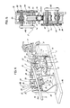
- the delivery drive means 8 is operatively connected to the rotary drive means 4 via differential speed change means afforded by a planetary gear mechanism.
- the planetary gear mechanism has a sun gear 81 disposed inside the rotary frame front end plate 35 concentrically with the rotary frame 34 and free to rotate relative to the frame 34.
- the sun gear 81 has a boss 81a which is rotatably fitted around the boss 35a of the rotary frame 34 with bearings 80 interposed therebetween and which extends outward beyond the boss 35a.
- a toothed pulley 88 is mounted on the outer end of the boss 81a and coupled to an auxiliary drive unit 87 mounted on the fixed frame 31.
- a rotary shaft 86 for a planetary gear 82 is supported on the front end plate 35 of the rotary frame 34, and the planetary gear 82 is in mesh with the sun gear 81.
- the shaft 86 is coupled at its rear end to an output shaft 89 via bevel gears 83, 84.
- the output shaft 89 is mounted on the rotary frame 34 and intersects the path of movement of the support member 100 at right angles therewith.
- the shaft 89 carries a gear 84a at one end.
- the gear 84a is in mesh with a gear 85 mounted on the shaft 71a of the front timing pulley 71 to constitute the delivery drive means 8.
- the sun gear 81 rotates to control the speed of rotation of the planetary gear 82 about its own axis. Accordingly, the speed of travel of the timing belt 73 is adjustable without changing the speed of rotation of the rotary frame 34.
- the paper tube production apparatus of the present invention can be equipped with the tape winding device 2 and/or the tube press 54 upstream from the tube rotating-drawing device 3.
- the tape winding device 2 operates to helically wind paper tape on the mandrel 12 into a paper tube and, at the same time, guide the tube to the press 54.
- the tape winding device 2 includes a belt support 21 on a rotary table 15 which is mounted on the base 1 and rotatable in a horizontal plane.
- Slide blocks 22, 22 are mounted on opposite ends of the upper portion of the support 21 and are movable toward or away from each other.
- a screw rod 23 rotatably supported on each end of the support 21 is screwed through the slide block 22, which is therefore shiftable by the thrust produced by rotating the screw rod 23, whereby the tension on the belt 29 to be described is adjustable.
- a driven roller 24 is horizontally supported by each block 22.
- a drive roller 27 having a larger diameter than the driven roller 24 is horizontally mounted on the support 21 centrally of its lower portion.
- the aforementioned motor 26 is coupled to the drive roller 27 via reduction gear means 25.
- Two guide rollers 28, 28 are arranged above and close to the drive roller 27.
- the belt 29 is wound on the mandrel 12 by one turn and endlessly reeved around the drive roller 27 and the driven rollers 24, 24 over the guide rollers 28, 28.
- the outer periphery of the rotary table 15 is locally toothed as indicated at 16, and a gear 17 meshing with the toothed portion 16 is coupled to a manually rotatable handle 19 via a worm 18.
- the tube press 54 comprises two support plates 56, 56 provided upright on the base 1 to intersect the mandrel 12, and three press rollers 55 spaced apart approximately equidistantly around the mandrel 12 inside the support plates 56, 56 and movable toward or away from the axis of the mandrel 12.
- the support plates 56 are each formed with a hole 56a for passing therethrough the mandrel 12 and the paper tube 92 (not shown in Fig. 6) with a clearance formed around the tube.
- the support plates 56, 56 are interconnected by stays 57 arranged around the mandrel at equal spacings.
- Each press roller 55 is rotatably supported at its opposite ends by a holder 58, which has two parallel rods 59, 59 projecting outward therefrom and slidably extending through the stay 57.
- a spring 50 is provided around each rod 59 for pressing the press roller 55 against the mandrel 12.
- the tube production apparatus can be provided with one or some of the resin-coated tape feeder 93, resin applicator stand 94, drying oven 95, grinding stand 96 and cutter 97 for cutting the tube 92 to a specified length, as arranged downstream from the apparatus as required.
- a tape 91c prepared by coating a nonwoven fabric with a resion solution is supplied to the tube 92 on the mandrel 12 by the applicator 93.
- the resin applicator stand 94 is adapted to apply a resin solution onto the resin-coated tape 91c on the paper tube 92 and scrape off an excess of the solution.
- the drying oven 95 incorporates a heater (not shown) therein for solidifying the applied resin by drying.
- the grinding stand 96 is adapted to grind the resin layer over the tube surface to give a smooth surface finish.
- the cutter 97 includes a rotary blade (not shown) rotatable in a plane perpendicular to the paper tube and movable along the mandrel 12 in synchronism with the tube for cutting the tube to the specified length.
- the tube production line is operated in the following manner.
- the support members 100 and the delivery assemblies 7 are held away from the mandrel 12 to leave open the path of travel of paper tape on the mandrel 12.
- Paper tape is helically wound on the mandrel 12 by the tape winding device 2 into a paper tube, which is fed to the tube press 54.
- the paper tube While being rotated, the paper tube is pressed against the mandrel 12 by the press rollers 55 of the press 54, whereby the paper tape is tightly wound on the mandrel 12.
- the paper tube further advances forward into the tube rotating-drawing device 3.
- the rotary drive means 4 for the rotary frame 34, the delivery drive means 8 and the pressing means 6 on the support members 100 are initiated into operation.
- the timing belts 73 on the delivery assemblies 7 are also driven, forcing the paper tube 92 forward axially of the mandrel 12.
- the winding device 2 merely assists in winding the tape helically on the mandrel 12 in the current state.
- the speed of production of the tube is dependent on the revolution of the delivery assemblies 7 and can be stabilized per unit time. Consequently, the line incorporating the foregoing devices as associated with the tube production apparatus of the invention is smoothly operable.
- the speed of transport by the delivery assemblies 7 is variable as desired by operating the auxiliary drive unit 87. This make it possible to transport the paper tape axially of the mandrel at a speed accurately corresponding to the speed at which the tape is wound into the paper tube. Consequently, the tube obtained is free from tape-to-tape clearances.
- the press rollers 55 of the press 54 are arranged in parallel to the mandrel 12, the friction between the paper tube and the rollers 55 pressing the tube against the mandrel 12 exerts a braking force on the tube against its advance.
- the subsequent rotating-drawing device 3 exerts a great drawing force on the paper tube as already stated, so that the tube is forcibly delivered from the press 54 into the rotating-drawing device 3. This not only eliminates the variations in the tube production speed that could result from an insufficient drawing force on the tube but also makes it possible to accurately determine the tube production speed per unit time, consequently ensuring smooth operation of the line wherein the processing devices are connected to the tube production apparatus downstream thereof as seen in Fig. 1A.
- the rotating-drawing device 3 uniformly presses the tube against the mandrel 12 with the timing belts 73 which are opposed to each other diametrically of the mandrel, therefore holds the mandrel straight without warping even if the mandrel has a small diameter to advance the tube smoothly axially of the mandrel, and making it possible to wind up the paper tape into a tube of small diameter at a high speed to achieve a greatly improved production efficiency.
- the timing belt 73 used as the delivery member of the delivery assembly 7 in the foregoing embodiment can be replaced by a flat belt 77 shown in Fig. 9.
- the belt 77 is reeved around pulleys 73a with a flat rim. It is desirable that like the belt 73, the belt 77 be provided with lips 74, 74 adhered to its outer surface to define a groove 75 between the lips.
- a chain 79 is also usable as shown in Figs. 10 and 11.
- Each of the links of the chain 79 is provided with a mount 78 having attached thereto a rubber tread 79b with a V-groove 79c. The paper tube is brought into contact with the grooved side of the tread.
- the paper tube need not always be forwarded by driving the timing belt, the flat belt or the chain with the treads, but the rollers 71 72 and 76 can be in direct pressing contact with the paper tube to deliver the tube axially of the mandrel by the rotation of the rollers.
- the tube production line shown in Fig. 1A can be so positioned that the mandrel 12 extends vertically from above for producing the tube 92.
- the mandrel needs only to be supported at its upper end so as to extend downward and can therefore be supported by simplified lightweight means unlike the conventional arrangement wherein the mandrel is supported at its base end and positioned horizontally.
- the vertical line although necessitating a higher ceiling for the factory, can be installed in a greatly reduced space unlike the conventional production line. Additionally, the component devices required for the tube production line can be installed horizontally on different floors of the factory, therefore need not be positioned at a definite level and can be installed easily.
- the frames for the devices can be small-sized to compact the entire line, hence a reduced equipment cost.
Landscapes
- Engineering & Computer Science (AREA)
- Mechanical Engineering (AREA)
- Robotics (AREA)
- Making Paper Articles (AREA)
- Storing, Repeated Paying-Out, And Re-Storing Of Elongated Articles (AREA)
Abstract
Description
- The present invention relates to an apparatus for producing a tube by helically winding tape on a mandrel.
- Cores or paper tubes are produced generally by helically winding paper tape in layers around a mandrel in the form of a round rod to form a tubular body and continuously delivering the tubular body from the forward end of the mandrel. Two-pulley and three-pulley devices shown in Figs. 12 and 13, respectively, are conventionally used for winding paper tape around the mandrel.
- The
tape winding device 2 shown in Fig. 12 has tworotatable pulleys mandrel 12. Abelt 29 obliquely wound on themandrel 12 by one turn is endlessly reeved around the twopulleys - The tape winding three-
pulley device 2 shown in Fig. 13 comprises one mainrotatable pulley 13 disposed on one side of amandrel 12, and first and second two auxiliaryrotatable pulleys 13a, 13b arranged on the other side of the mandrel. Afirst belt 29 is endlessly reeved around the upper portion of themain pulley 13 and the firstauxiliary pulley 13a, and a second belt 29a is endlessly wound around the lower portion of themain pulley 13 and the second auxiliary pulley 13b. The first andsecond belts 29, 29a are wound on themandrel 12 by one turn symmetrically. - With these two-pulley and three-pulley devices,
paper tapes 91a, 91b paid off from twotape feeders mandrel 12 and thebelt 29 orbelts 29, 29a driven by the pulleys and helically wound on themandrel 12 into apaper tube 92 while being slipped on the mandrel by the friction between the tape and the belt. Thus, the belt or belts function to wind the paper tapes around the mandrel and also to forward the paper tube axially thereof. - However, when the belt is tensioned as wound around a mandrel of small diameter as stated above and is driven in this state at a high speed for producing a paper tube of small diameter, the mandrel of small diameter warps in an undulating fashion, rendering the paper tube no longer smoothly rotatable and movable axially thereof and making it impossible to obtain a paper tube of commercial value. With the conventional paper tape winding device, therefore, there arises a need to lower the tension on the belt and to drive the belt at a reduced speed. Consequently, when producing a paper tube, for example, having a small inside diameter of 6 mm and a wall thickness of 2 mm, the device is as low as about 2 m/min in production speed and is very low in production efficiency.
- Further regardless of whether paper tubes have a small diameter, medium wall thickness or large wall thickness, those for a particular use are required of very high pressure resistance. To impart improved pressure resistance to the paper tube, the paper tape must be subjected to great back tension and tightly wound on the mandrel. Nevertheless, if the belt wound on the mandrel by one turn is driven to wind the paper tape around the mandrel and also to forward the resulting paper tube as in the conventional practice, slippage is likely to occur between the paper tube and the tape, whereas increased back tension on the paper tape permits slippage of the belt. Since the torque of the pulley is transmitted to the tape by virtue of the friction between the pulley and the belt and also the friction between the belt and the tape, the power transmission efficiency is low. Consequently, even if an increased torque is given to the pulley, difficulty is encountered in winding the highly tensioned tape around the mandrel helically continuously. Thus, it is difficult to produce paper tubes having the desired pressure resistance.
- Further when the belt is driven as wound on the mandrel obliquely, the belt acts to advance axially of the mandrel at the portion thereof around the mandrel, while the tension on the belt retracts the belt axially of the mandrel. Since this motion is repeated, the belt is always reciprocatingly moved over a small distance axially of the mandrel. Because the paper tape is wound on the mandrel by the belt reciprocatingly moving in this fashion, a clearance is liable to occur between the adjacent two portions of the tape wound on the mandrel. Such a clearance not only impairs the strength of the paper tube but also varies the speed of axial transport of the tube.
- Before the paper tube is made into a finished product, the tube is not infrequently subjected to aftertreatments such as coating of the tube surface with resin and grinding of the resulting surface. However, the conventional machine for producing paper tubes is low in its force to deliver the paper tube axially thereof, so that such aftertreatments offer increased resistance to the axial movement of the tube to result in variations in the speed of axial movement of the tube and make the tube production speed unstable, if the treatments are conducted in sequence by devices connected to the production line downstream from the machine. Consequently, the aftertreatment devices are not in smooth operative relation with the machine, failing to produce products of good quality. With the conventional device, therefore, the paper tube is cut to a specified length, and the cut tube is then treated as required by another processing line, hence a poor production efficiency.
- The main object of the present invention is to provide an apparatus for producing a paper tube or like tube at a constant speed which apparatus is adapted to deliver the tube axially thereof with a great force while rotating the tube without warping the mandrel so that tape can be helically wound on the mandrel tightly with a great torsional force without creating any tape-to-tape clearance.
- To fulfill the above object, the present invention provides an apparatus for producing a tube which comprises a tube rotating-drawing device in place of or in addition to a conventional tape winding device. The tube rotating-drawing device comprises a rotary frame coupled to rotary drive means and rotatable in a fixed position around a mandrel, support members provided on the rotary frame with the mandrel positioned between the support members and movable toward or away from the mandrel, means for pressing the support members against the mandrel, and a delivery assembly mounted on each of the support members and having a delivery member coupled to delivery drive means and movable along an endless path or rotatable in a plane containing the axis of the mandrel for delivering the tube formed on the mandrel axially thereof by frictional contact of the delivery member with the tube on the mandrel.
- Fig. 1 is a plan view of an apparatus of the invention for producing a paper tube;
- Fig. 1A is a plan view showing a paper tube production line embodying the invention;
- Fig. 2 is a sectional view of a tube rotating-drawing device;
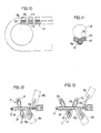
- Fig. 3 is a perspective view of a delivery assembly;
- Fig. 4 is a perspective view of the delivery assembly as it is seen from the opposite side of Fig. 3;
- Fig. 5 is a view in section taken along the line V-V in Fig. 2;
- Fig. 6 is a perspective view of a tape winding device and a tube press;
- Fig. 7 is a perspective view showing a drive system for the tape winding device;
- Fig. 8 is a view in section taken along the line VIII-VIII in Fig. 6;
- Fig. 9 is a fragmentary perspective view of a flat belt as another example of delivery member;
- Fig. 10 is a fragmentary front view showing a chain serving as a delivery member;
- Fig. 11 is a view in section taken along the line XI-XI in Fig. 10;
- Fig. 12 is a plan view of a conventional tube production apparatus comprising a two-pulley tape winding device; and
- Fig. 13 is a plan view of another conventional tube production apparatus comprising a three-pulley tape winding device.
- Although the invention will be described below with reference to the case wherein paper tape is used for making a paper tube, the invention is not limited to the use of paper but is of course useful for forming tape of nonwoven fabric, synthetic resin or the like for forming tubes.
- With reference to Fig. 1, the paper tube production apparatus of the invention comprises a
mandrel 12 horizontally disposed on a base 1 and fixed at its one end to the base, a pair ofpaper tape feeders - The apparatus of the invention can be selectively equipped with various devices in accordance with the size of paper tube to be produced, the characteristics required of the tube, the desired production efficiency, etc. Fig. 1A shows an example of paper tube production line including various devices, i.e., a
tube press 54 and atape winding device 2 which are arranged upstream from the tube rotating-drawing device 3; and a resin-coatedtape feeder 93,resin applicator stand 94, dryingoven 95, grindingstand 96,tube cutter 97 andtube support 98 which are arranged downstream from the tube rotating-drawing device 3. Such components can be selected as desired for use in combination with the paper tube production apparatus of Fig. 1. - The terms "front" and "rear" as used herein refer respectively to the downstream side and the upstream side of the production line.
- The
mandrel 12 extends horizontally toward the front and is supported by abracket 11 at the rear end of the base 1. The front end of the mandrel is left unsupported. - Paper tape feed means preferably comprises two feeders, i.e., the above-mentioned
tape feeders paper tube 91a for forming the lowemost layer of a core orpaper tube 92 is obliquely fed to themandrel 12 from one of thefeeders 90. Thepaper tape 91a is coated on the rear surface thereof with paraffin to reduce the friction between the tape and themandrel 12. A plurality of paper tapes 91b lapping over one another at the side edge are fed obliquely to themandrel 12 from theother feeder 90. A glue is applied to the rear surface of each tape 91b by anapplicator 99. - The number of tape feeders is not limited to two but the
tapes 91a, 91b can be supplied from a single feeder, or three or more feeders. - The tube rotating-drawing device 3 has a
fixed frame 31 in the form of a hollow cylinder and mounted horizontally on the base 1 concentrically with themandrel 12. Themandrel 12 extends through aboss 33a on arear end plate 33, with a clearance formed around the mandrel, and has its front end positioned close to a boss 32a on a front end plate 32. - A
rotary frame 34 in the form of a hollow cylinder is housed in thefixed frame 31 rotatably and concentrically with themandrel 12.Central bosses opposite end plates rotary frame 34 are rotatably supported bybearings bosses 32a, 33a of the fixedframe 31. Thus, therotary frame 34 is free to rotate within thefixed frame 31. - Rotary drive means 4 mounted on the fixed
frame 31 is coupled to therotary frame 34 to drivingly rotate theframe 34. The drive means 4 includes ashaft 41 rotatably extending through the front end plate 32 of the fixedframe 31 and coupled at its outer end to amotor 45 by a chain 44. Apinion 42 is mounted on the inner end of theshaft 41. Themotor 45 and a motor 26 (Fig. 6) for thetape winding device 2 are coupled to a rotation control unit (not shown) of the inverter type, whereby the speed of rotation of therotary frame 34 is variable in accordance with the speed of travel of abelt 29 of thetape winding device 2. - An annular large gear 43 secured to the
front end plate 35 of therotary frame 34 concentrically with themandrel 12 is in mesh with thepinion 42. - As seen in Figs. 2 and 3, a pair of
support members rotary frame 34, with themandrel 12 interposed therebetween. - Each
support member 100 is slidably supported as held between a pair ofguide plates rotary frame 34 and is movable forward and rearward, and also toward or away from themandrel 12. Thesupport member 100 is supported at its front and rear portions byparallel levers rotary frame 34 forwardly and rearwardly movably. - With reference to Figs. 2 and 4, pressing means 6 is connected to an intermediate portion of the
support member 100 for pressing the support member against themandrel 12. The pressing means 6 includes toggle links 61, 62 respectively pivoted to thesupport member 100 and abracket 60 mounted on the inner surface of therotary frame 34, and apush rod 63 disposed in parallel to themandrel 12 and pivoted to the connection between the twolinks - The
push rod 63 slidably extends through therear end plate 36 of therotary frame 34 and is revolvably connected to a cylinder assembly 64 mounted on theboss 33a of the fixedframe 31. Therod 63 is movable forward or rearward. The cylinder assembly 64 comprises ashort cylinder 65 secured to theend plate 33 of the fixedframe 31 and surrounding theboss 33a concentrically therewith, and anannular piston 66 slidably provided between theboss 33a and thecylinder 65. - A slidable tubular piston rod 67 fitted around the
boss 33a extends from thepiston 66 forward beyond the front end of thecylinder 65 and is formed with acircumferential groove 68 at its front end. Thepush rod 63 is connected to a ring plate 69 rotatably fitted in thegroove 68. - A pressure fluid, when supplied to the cylinder assembly 64, advances the piston rod 67, which in turn pushes the
push rods 63 forward, causing the toggle links to forcibly press thesupport members 100 against themandrel 12. - Owing to the pivotal movement of the
parallel link plates support member 100 approaches themandrel 12 while slightly advancing axially of themandrel 12. - The ring plate 69 connecting the
push rods 63 to the cylinder assembly 64 is rotatably engaged in thecircumferential groove 68 in the piston rod 67 of the assembly 64, so that thepush rods 63 are movable around themandrel 12 with therotary frame 34 by the rotation of thisframe 34 and can also be pushed forward by the piston rod 67. - The
paper tapes 91a, 91b wound on themandrel 12 and brought into therotary frame 34 are withdrawn therefrom axially of themandrel 12 by adelivery assembly 7 mounted on eachsupport member 100, in pressing contact with the tapes. - The
delivery assembly 7 of the present embodiment comprises a pair of timing pulleys 71, 72 supported respectively at the front and rear ends of thesupport member 100, and atiming belt 73 endlessly reeved around the two pulleys. - With reference to Fig. 5,
urethane rubber lips timing belt 73 along the respective side edges thereof over the entire circumference of the belt, and afurrow 75 formed between thelips timing belt 73 serves as a member for delivering the paper tube axially thereof. A plurality ofauxiliary rollers 76 are closely arranged between the two timing pulleys 71, 72 and rotatably mounted on thesupport member 100. Where thetiming belt 73 faces themandrel 12, theauxiliary rollers 76 are in contact with the rear surface of thebelt 73 to guide the belt for straight travel. - Delivery drive means 8 is coupled to the
front timing pulley 71 of eachdelivery assembly 7. The delivery drive means 8 is operatively connected to the rotary drive means 4 via differential speed change means afforded by a planetary gear mechanism. - With reference to Fig. 2, the planetary gear mechanism has a
sun gear 81 disposed inside the rotary framefront end plate 35 concentrically with therotary frame 34 and free to rotate relative to theframe 34. Thesun gear 81 has aboss 81a which is rotatably fitted around theboss 35a of therotary frame 34 withbearings 80 interposed therebetween and which extends outward beyond theboss 35a. A toothed pulley 88 is mounted on the outer end of theboss 81a and coupled to anauxiliary drive unit 87 mounted on the fixedframe 31. - A
rotary shaft 86 for aplanetary gear 82 is supported on thefront end plate 35 of therotary frame 34, and theplanetary gear 82 is in mesh with thesun gear 81. Theshaft 86 is coupled at its rear end to anoutput shaft 89 viabevel gears output shaft 89 is mounted on therotary frame 34 and intersects the path of movement of thesupport member 100 at right angles therewith. Theshaft 89 carries agear 84a at one end. Thegear 84a is in mesh with agear 85 mounted on theshaft 71a of thefront timing pulley 71 to constitute the delivery drive means 8. - When the
rotary frame 34 is rotated with thesun gear 81 at rest, theplanetary gear 82 on theframe 34 rotates about its own axis while revolving along the outer periphery of thesun gear 81. The rotation of theplanetary gear 82 about its own axis causes the bevel gears 83, 84 and thegears pulley 71, which in turn drives thebelt 73. With therotary frame 34 held in rotation in the meantime, eachtiming belt 73 is thus driven while eachdelivery assembly 7 is being revolved around themandrel 12. - When the
auxiliary drive unit 87 is operated with therotary frame 34 held in rotation, thesun gear 81 rotates to control the speed of rotation of theplanetary gear 82 about its own axis. Accordingly, the speed of travel of thetiming belt 73 is adjustable without changing the speed of rotation of therotary frame 34. - When required, the paper tube production apparatus of the present invention can be equipped with the
tape winding device 2 and/or thetube press 54 upstream from the tube rotating-drawing device 3. - The
tape winding device 2 operates to helically wind paper tape on themandrel 12 into a paper tube and, at the same time, guide the tube to thepress 54. - With reference to Figs. 6 and 7, the
tape winding device 2 includes abelt support 21 on a rotary table 15 which is mounted on the base 1 and rotatable in a horizontal plane. Slide blocks 22, 22 are mounted on opposite ends of the upper portion of thesupport 21 and are movable toward or away from each other. - A
screw rod 23 rotatably supported on each end of thesupport 21 is screwed through theslide block 22, which is therefore shiftable by the thrust produced by rotating thescrew rod 23, whereby the tension on thebelt 29 to be described is adjustable. A drivenroller 24 is horizontally supported by eachblock 22. Adrive roller 27 having a larger diameter than the drivenroller 24 is horizontally mounted on thesupport 21 centrally of its lower portion. Theaforementioned motor 26 is coupled to thedrive roller 27 via reduction gear means 25. - Two
guide rollers drive roller 27. Thebelt 29 is wound on themandrel 12 by one turn and endlessly reeved around thedrive roller 27 and the drivenrollers guide rollers - The outer periphery of the rotary table 15 is locally toothed as indicated at 16, and a
gear 17 meshing with thetoothed portion 16 is coupled to a manuallyrotatable handle 19 via aworm 18. Thehandle 19, when turned, rotates the rotary table 15 and thesupport 21 to thereby alter the angle at which thebelt 29 is wound on themandrel 12, whereby the angle at which the tape is to be wound is variable as desired in accordance with the tape width. - Although the tape winding device described above is preferable to use, one of the conventional devices shown in Figs. 12 and 13 is also usable.
- With reference to Figs. 6 and 8, the
tube press 54 comprises twosupport plates mandrel 12, and threepress rollers 55 spaced apart approximately equidistantly around themandrel 12 inside thesupport plates mandrel 12. Thesupport plates 56 are each formed with ahole 56a for passing therethrough themandrel 12 and the paper tube 92 (not shown in Fig. 6) with a clearance formed around the tube. Thesupport plates stays 57 arranged around the mandrel at equal spacings. - Each
press roller 55 is rotatably supported at its opposite ends by aholder 58, which has twoparallel rods stay 57. Aspring 50 is provided around eachrod 59 for pressing thepress roller 55 against themandrel 12. - As shown in Fig. 1A and already stated, the tube production apparatus can be provided with one or some of the resin-coated
tape feeder 93,resin applicator stand 94, dryingoven 95, grindingstand 96 andcutter 97 for cutting thetube 92 to a specified length, as arranged downstream from the apparatus as required. - A tape 91c prepared by coating a nonwoven fabric with a resion solution is supplied to the
tube 92 on themandrel 12 by theapplicator 93. - The resin applicator stand 94 is adapted to apply a resin solution onto the resin-coated tape 91c on the
paper tube 92 and scrape off an excess of the solution. - The drying
oven 95 incorporates a heater (not shown) therein for solidifying the applied resin by drying. - The grinding
stand 96 is adapted to grind the resin layer over the tube surface to give a smooth surface finish. - The
cutter 97 includes a rotary blade (not shown) rotatable in a plane perpendicular to the paper tube and movable along themandrel 12 in synchronism with the tube for cutting the tube to the specified length. - The tube production line is operated in the following manner.
- First, the
support members 100 and thedelivery assemblies 7 are held away from themandrel 12 to leave open the path of travel of paper tape on themandrel 12. - Paper tape is helically wound on the
mandrel 12 by thetape winding device 2 into a paper tube, which is fed to thetube press 54. - While being rotated, the paper tube is pressed against the
mandrel 12 by thepress rollers 55 of thepress 54, whereby the paper tape is tightly wound on themandrel 12. - The paper tube further advances forward into the tube rotating-drawing device 3.
- Upon the egress of the taper tube from the downstream side of the device 3, the rotary drive means 4 for the
rotary frame 34, the delivery drive means 8 and thepressing means 6 on thesupport members 100 are initiated into operation. - With the rotation of the
frame 34, thesupport members 100 and thedelivery assemblies 7 revolve around themandrel 12, while thedelivery assemblies 7 on thesupport members 100 exert great pressure directly on thetube 92 covering themandrel 12. - The
timing belts 73 on thedelivery assemblies 7 are also driven, forcing thepaper tube 92 forward axially of themandrel 12. - While the
rotary frame 34 is in rotation in a fixed position about themandrel 12, thedelivery assemblies 7 draw the paper tube into theframe 34 axially of themandrel 12. - Since the torque of the
rotary frame 34 and the force of thedelivery assemblies 7 in the axial direction of themandrel 12 act on the paper tube at the same time, the windingdevice 2 merely assists in winding the tape helically on themandrel 12 in the current state. - The
delivery assemblies 7, which are forcibly pressed toward the axis of themandrel 12 by thepressing means 6, tightly wind the paper tape on themandrel 12 while exerting great pressure on the tape, with the result that thepaper tube 92 obtained has high pressure resistance. - Since the paper tape is drawn into the
rotary frame 34 axially of themandrel 12 by thedelivery assemblies 7 on theframe 34, the speed of production of the tube is dependent on the revolution of thedelivery assemblies 7 and can be stabilized per unit time. Consequently, the line incorporating the foregoing devices as associated with the tube production apparatus of the invention is smoothly operable. - In the case where the paper tape is helically wound on the
mandrel 12 into a paper tube by the rotating-drawing device 3 only, it is necessary to resort to manual work initially for helically winding the tape on the mandrel into the tube and placing the tube as wound on the mandrel between the timingbelts 73 of the device 3 in engagement therewith. - With the
rotary frame 34 driven at a constant speed, the speed of transport by thedelivery assemblies 7 is variable as desired by operating theauxiliary drive unit 87. This make it possible to transport the paper tape axially of the mandrel at a speed accurately corresponding to the speed at which the tape is wound into the paper tube. Consequently, the tube obtained is free from tape-to-tape clearances. - Because the
press rollers 55 of thepress 54 are arranged in parallel to themandrel 12, the friction between the paper tube and therollers 55 pressing the tube against themandrel 12 exerts a braking force on the tube against its advance. However, the subsequent rotating-drawing device 3 exerts a great drawing force on the paper tube as already stated, so that the tube is forcibly delivered from thepress 54 into the rotating-drawing device 3. This not only eliminates the variations in the tube production speed that could result from an insufficient drawing force on the tube but also makes it possible to accurately determine the tube production speed per unit time, consequently ensuring smooth operation of the line wherein the processing devices are connected to the tube production apparatus downstream thereof as seen in Fig. 1A. - Furthermore, the rotating-drawing device 3 uniformly presses the tube against the
mandrel 12 with thetiming belts 73 which are opposed to each other diametrically of the mandrel, therefore holds the mandrel straight without warping even if the mandrel has a small diameter to advance the tube smoothly axially of the mandrel, and making it possible to wind up the paper tape into a tube of small diameter at a high speed to achieve a greatly improved production efficiency. - The
timing belt 73 used as the delivery member of thedelivery assembly 7 in the foregoing embodiment can be replaced by aflat belt 77 shown in Fig. 9. Thebelt 77 is reeved around pulleys 73a with a flat rim. It is desirable that like thebelt 73, thebelt 77 be provided withlips groove 75 between the lips. - In place of the
timing belt 73, achain 79 is also usable as shown in Figs. 10 and 11. Each of the links of thechain 79 is provided with amount 78 having attached thereto arubber tread 79b with a V-groove 79c. The paper tube is brought into contact with the grooved side of the tread. - According to the present invention, the paper tube need not always be forwarded by driving the timing belt, the flat belt or the chain with the treads, but the
rollers 71 72 and 76 can be in direct pressing contact with the paper tube to deliver the tube axially of the mandrel by the rotation of the rollers. In this case, it is desirable to form the outer peripheral portion of each roller by a material, such as urethane rubber, having a great coefficient of friction, with a circumferential groove formed in the periphery of the roller, to increase the area of contact between the roller and the paper tube. - The tube production line shown in Fig. 1A can be so positioned that the
mandrel 12 extends vertically from above for producing thetube 92. In this case, the mandrel needs only to be supported at its upper end so as to extend downward and can therefore be supported by simplified lightweight means unlike the conventional arrangement wherein the mandrel is supported at its base end and positioned horizontally. - The vertical line, although necessitating a higher ceiling for the factory, can be installed in a greatly reduced space unlike the conventional production line. Additionally, the component devices required for the tube production line can be installed horizontally on different floors of the factory, therefore need not be positioned at a definite level and can be installed easily. The frames for the devices can be small-sized to compact the entire line, hence a reduced equipment cost.
- It is further possible to provide a plurality of tube production lines vertically side by side and to transmit power to the individual lines through a couter shaft interconnecting the lines. Thus, all the tube production lines can be operated by one motor for driving the countershaft.
- Various modifications can be made by one skilled in the art without departing from the scope of the invention as defined in the appended claims.
Claims (8)
a rotary frame (34) coupled to rotary drive means (4) and rotatable in a fixed position around the mandrel (12),
a support member (100) supported on the rotary frame (34) at one side of the mandrel (12) and movable toward or away from the mandrel (12),
means (6) for pressing the support member (100) against the mandrel (12), and
a delivery assembly (7) mounted on the support member (100) and having a delivery member coupled to delivery drive means (8) and movable along an endless path or rotatable in a plane containing the axis of the mandrel (12) for delivering the tube from the mandrel axially thereof by frictional contact of the delivery member with the tube on the mandrel.
Applications Claiming Priority (2)
| Application Number | Priority Date | Filing Date | Title |
|---|---|---|---|
| JP63128872A JPH01299171A (en) | 1988-05-26 | 1988-05-26 | Machine for manufacturing paper tube and device for rotatingly drawing out paper tube |
| JP128872/88 | 1988-05-26 |
Publications (3)
| Publication Number | Publication Date |
|---|---|
| EP0343601A2 true EP0343601A2 (en) | 1989-11-29 |
| EP0343601A3 EP0343601A3 (en) | 1991-12-18 |
| EP0343601B1 EP0343601B1 (en) | 1993-11-03 |
Family
ID=14995448
Family Applications (1)
| Application Number | Title | Priority Date | Filing Date |
|---|---|---|---|
| EP89109281A Expired - Lifetime EP0343601B1 (en) | 1988-05-26 | 1989-05-23 | Apparatus for producing tube |
Country Status (6)
| Country | Link |
|---|---|
| US (1) | US4952202A (en) |
| EP (1) | EP0343601B1 (en) |
| JP (1) | JPH01299171A (en) |
| KR (1) | KR930004066B1 (en) |
| CN (1) | CN1015312B (en) |
| DE (1) | DE68910381T2 (en) |
Cited By (3)
| Publication number | Priority date | Publication date | Assignee | Title |
|---|---|---|---|---|
| WO1993023233A1 (en) * | 1992-05-15 | 1993-11-25 | Delaware Capital Formation, Inc. | Apparatus for adjustment of the spacing of film drive assemblies in a tubular film forming device |
| EP1625012A1 (en) * | 2003-05-15 | 2006-02-15 | Fabio Perini S.p.A. | Machine and method for forming helically wound paper tubes having improved mechanical resistance |
| EP2061640A4 (en) * | 2006-09-05 | 2010-03-17 | Vetco Gray Scandinavia As | Method and assembly for the production of a homogenous composite pipe of unspecified length |
Families Citing this family (20)
| Publication number | Priority date | Publication date | Assignee | Title |
|---|---|---|---|---|
| US5214988A (en) * | 1992-02-05 | 1993-06-01 | Middlesex Paper Tube Co. | Tube positioning apparatus |
| US20040050228A1 (en) * | 2002-09-16 | 2004-03-18 | Borzym John J. | Mandrel rod with internal support rollers |
| DE10261256B4 (en) * | 2002-12-20 | 2004-11-11 | Windmöller & Hölscher Kg | Bottoming device |
| SE525100C2 (en) * | 2003-04-01 | 2004-11-30 | Core Link Ab | Device for applying a sheet of material |
| CN100341691C (en) * | 2004-07-15 | 2007-10-10 | 杭州保力洁包装有限公司 | Method for producing paper tube |
| KR100746170B1 (en) * | 2005-05-12 | 2007-08-03 | 주식회사 다인기술 | Method and apparatus for producing paper tube having polygonal cross section, and paper tube manufactured by the method |
| US7887474B2 (en) * | 2007-06-07 | 2011-02-15 | St. Marys Box Company, Inc. | Article forming paper wrapping device |
| CN101797820B (en) * | 2009-02-11 | 2011-06-15 | 王殿海 | Spiral square paper tube manufacturing equipment |
| CN102152499A (en) * | 2010-12-31 | 2011-08-17 | 陈裕金 | Reel machine |
| CN102896809A (en) * | 2012-11-13 | 2013-01-30 | 吴江久升纸业有限公司 | Double-color paper tape winding machine for paper tube |
| CN102922779B (en) * | 2012-11-16 | 2015-04-01 | 金红叶纸业集团有限公司 | Paper tube forming device |
| CN105479820B (en) * | 2015-11-24 | 2017-09-19 | 周胡琴 | Tubulose corrugated paper covers forming machine with tapping mechanism and material cutting mechanism |
| CN105398092B (en) * | 2015-11-24 | 2017-09-12 | 周胡琴 | Spark plug paper sleeve forming machine with flexible glue-injection box bottom plate and material cutting mechanism |
| CN105365268B (en) * | 2015-11-24 | 2017-08-01 | 温州智信机电科技有限公司 | Spark plug paper sleeve forming machine with elastic injecting glue box plate and video monitoring camera |
| CN105383096B (en) * | 2015-11-24 | 2017-08-01 | 温州智信机电科技有限公司 | A kind of spark plug paper sleeve forming machine of the flexible glue-injection box bottom plate of band |
| CN108284584B (en) * | 2018-03-19 | 2023-09-01 | 常州聚豪电气有限公司 | Polyester insulating tube processing device and processing technology |
| CN108312482B (en) * | 2018-03-19 | 2024-04-30 | 常州聚豪电气有限公司 | Mandrel supporting seat and driving device thereof |
| CN112192906A (en) * | 2019-07-07 | 2021-01-08 | 天津康利特变机电科技有限责任公司 | Intelligent full-automatic transformer crepe paper tube machine |
| CN110901176A (en) * | 2019-12-24 | 2020-03-24 | 嘉善永易胶粘制品有限公司 | A forming machine for producing viscose paper tubes |
| CN115384082B (en) * | 2022-08-31 | 2023-05-26 | 浙江鑫硕新材料有限公司 | Production device of glass fiber reinforced plastic cable conduit and control method thereof |
Family Cites Families (18)
| Publication number | Priority date | Publication date | Assignee | Title |
|---|---|---|---|---|
| US507764A (en) * | 1893-10-31 | spengler | ||
| US1374318A (en) * | 1920-03-01 | 1921-04-12 | Brown Co | Machine for straightening and sizing tubular bodies made from pulp |
| BE383882A (en) * | 1930-11-10 | |||
| US2723605A (en) * | 1950-08-19 | 1955-11-15 | William F Stahl | Apparatus for making laminated tubes |
| US2925621A (en) * | 1952-09-13 | 1960-02-23 | Kalle & Co Ag | Method of making regenerated cellulose sausage casings in spirally coiled form |
| US3068934A (en) * | 1954-01-15 | 1962-12-18 | Nicolet Ind Inc | Apparatus for producing helical air cell pipe covering |
| US2812007A (en) * | 1954-07-16 | 1957-11-05 | Painter Corp E Z | Apparatus for and method of continuously producing paint roller cover sections |
| US3567101A (en) * | 1968-01-02 | 1971-03-02 | Robert Mitchell Co Ltd The | Production of spirally wound pipe |
| US3817813A (en) * | 1970-02-23 | 1974-06-18 | Ici Ltd | Production of composite structures |
| FR2096787A1 (en) * | 1970-06-18 | 1972-02-25 | Ici Ltd | Composite tube with expanded material - wound on rigid core |
| DE2205604A1 (en) * | 1972-02-07 | 1973-08-23 | Rudolf Barainsky | METHOD AND DEVICE FOR THE CONTINUOUS MANUFACTURING OF FIBER-REINFORCED CAST RESIN PIPES |
| JPS532208B2 (en) * | 1973-07-23 | 1978-01-26 | ||
| DE2444507A1 (en) * | 1974-09-18 | 1976-04-01 | Dynamit Nobel Ag | Plastics tube continuously helically wound from strips on core - of end to end bars removed as tube is completed |
| DE2617140A1 (en) * | 1976-04-17 | 1977-10-27 | Berstorff Gmbh Masch Hermann | DEVICE FOR THE MANUFACTURING OF PIPES FROM STRAPS Wound In The Shape Of A SCREW |
| JPS53115464A (en) * | 1977-03-19 | 1978-10-07 | Fujimori Kogyo Co Ltd | Method of producing paper tube for winding core |
| SE410720B (en) * | 1978-11-01 | 1979-10-29 | Assi Can Ab | WAY TO MANUFACTURE CYLINDRICAL RODS |
| JPS5841195B2 (en) * | 1979-09-17 | 1983-09-10 | 七之助 生田 | Spiral paper tube manufacturing equipment |
| FR2567069B1 (en) * | 1984-07-03 | 1986-12-05 | Lhomme Sa | PROCESS AND DEVICE FOR MANUFACTURING A CALIBERED TUBE WITH VERY LOW SURFACE ROUGHNESS AND HIGH DIMENSIONAL STABILITY |
-
1988
- 1988-05-26 JP JP63128872A patent/JPH01299171A/en active Granted
-
1989
- 1989-02-16 US US07/311,451 patent/US4952202A/en not_active Expired - Fee Related
- 1989-03-28 CN CN89101922A patent/CN1015312B/en not_active Expired
- 1989-04-21 KR KR1019890005294A patent/KR930004066B1/en not_active Expired - Fee Related
- 1989-05-23 EP EP89109281A patent/EP0343601B1/en not_active Expired - Lifetime
- 1989-05-23 DE DE68910381T patent/DE68910381T2/en not_active Expired - Fee Related
Cited By (3)
| Publication number | Priority date | Publication date | Assignee | Title |
|---|---|---|---|---|
| WO1993023233A1 (en) * | 1992-05-15 | 1993-11-25 | Delaware Capital Formation, Inc. | Apparatus for adjustment of the spacing of film drive assemblies in a tubular film forming device |
| EP1625012A1 (en) * | 2003-05-15 | 2006-02-15 | Fabio Perini S.p.A. | Machine and method for forming helically wound paper tubes having improved mechanical resistance |
| EP2061640A4 (en) * | 2006-09-05 | 2010-03-17 | Vetco Gray Scandinavia As | Method and assembly for the production of a homogenous composite pipe of unspecified length |
Also Published As
| Publication number | Publication date |
|---|---|
| KR890017157A (en) | 1989-12-15 |
| CN1037863A (en) | 1989-12-13 |
| EP0343601A3 (en) | 1991-12-18 |
| DE68910381T2 (en) | 1994-05-26 |
| JPH01299171A (en) | 1989-12-01 |
| KR930004066B1 (en) | 1993-05-20 |
| DE68910381D1 (en) | 1993-12-09 |
| EP0343601B1 (en) | 1993-11-03 |
| CN1015312B (en) | 1992-01-22 |
| US4952202A (en) | 1990-08-28 |
| JPH0565428B2 (en) | 1993-09-17 |
Similar Documents
| Publication | Publication Date | Title |
|---|---|---|
| US4952202A (en) | Apparatus for producing tube | |
| JPS6335492B2 (en) | ||
| GB2082963A (en) | Improved dough forming dividing and cutting apparatus | |
| FI62015B (en) | ANORDINATION FOER SKAERNING AV BANFORMIGT MATERIAL | |
| US4351682A (en) | Flexible duct forming apparatus and method | |
| US3996093A (en) | Apparatus for producing transverse weld seams in a two-ply web of plastic film | |
| CN117696374B (en) | Rubberizing coating machine with feed is adjusted | |
| IT8267386A1 (en) | PAPER TUBES MANUFACTURING EQUIPMENT | |
| CN112607469A (en) | Winding mechanism of integrated paper winding machine | |
| CN112551226A (en) | Winding mechanism of paper winding machine | |
| US4099287A (en) | Cylindrical wound brush | |
| CN214445499U (en) | A square tube profile polishing machine | |
| CN212052073U (en) | Cloth cutting machine | |
| CN110014472B (en) | A convenient slicing device | |
| US1258731A (en) | Tube-machine. | |
| DE1635530A1 (en) | Machine for the production of multilayer fabrics | |
| CN223658525U (en) | Distance conveying mechanism for food packaging equipment | |
| CN218838820U (en) | Brush mucilage binding that fiber container stock processing was used is put | |
| CN220429479U (en) | Winding spiral forming mechanism of paper tube machine in vertical layout | |
| CN214652320U (en) | Winding mechanism of integrated paper winding machine | |
| CN2432606Y (en) | Paper-finding frame of upper paper box for colour enlarger | |
| CN220349172U (en) | Carton banding device for carton packing machine | |
| CN222593009U (en) | Packaging film conveying and leveling device | |
| US3127123A (en) | Tape slitting machine | |
| CN223800797U (en) | Multilayer paper tape gumming machine |
Legal Events
| Date | Code | Title | Description |
|---|---|---|---|
| PUAI | Public reference made under article 153(3) epc to a published international application that has entered the european phase |
Free format text: ORIGINAL CODE: 0009012 |
|
| AK | Designated contracting states |
Kind code of ref document: A2 Designated state(s): DE FR GB IT |
|
| 17P | Request for examination filed |
Effective date: 19901221 |
|
| PUAL | Search report despatched |
Free format text: ORIGINAL CODE: 0009013 |
|
| AK | Designated contracting states |
Kind code of ref document: A3 Designated state(s): DE FR GB IT |
|
| 17Q | First examination report despatched |
Effective date: 19921029 |
|
| GRAA | (expected) grant |
Free format text: ORIGINAL CODE: 0009210 |
|
| AK | Designated contracting states |
Kind code of ref document: B1 Designated state(s): DE FR GB IT |
|
| ITF | It: translation for a ep patent filed | ||
| REF | Corresponds to: |
Ref document number: 68910381 Country of ref document: DE Date of ref document: 19931209 |
|
| ET | Fr: translation filed | ||
| PLBE | No opposition filed within time limit |
Free format text: ORIGINAL CODE: 0009261 |
|
| STAA | Information on the status of an ep patent application or granted ep patent |
Free format text: STATUS: NO OPPOSITION FILED WITHIN TIME LIMIT |
|
| 26N | No opposition filed | ||
| PGFP | Annual fee paid to national office [announced via postgrant information from national office to epo] |
Ref country code: FR Payment date: 19990407 Year of fee payment: 11 |
|
| PGFP | Annual fee paid to national office [announced via postgrant information from national office to epo] |
Ref country code: GB Payment date: 19990511 Year of fee payment: 11 |
|
| PGFP | Annual fee paid to national office [announced via postgrant information from national office to epo] |
Ref country code: DE Payment date: 19990519 Year of fee payment: 11 |
|
| PG25 | Lapsed in a contracting state [announced via postgrant information from national office to epo] |
Ref country code: GB Free format text: LAPSE BECAUSE OF NON-PAYMENT OF DUE FEES Effective date: 20000523 |
|
| GBPC | Gb: european patent ceased through non-payment of renewal fee |
Effective date: 20000523 |
|
| PG25 | Lapsed in a contracting state [announced via postgrant information from national office to epo] |
Ref country code: FR Free format text: LAPSE BECAUSE OF NON-PAYMENT OF DUE FEES Effective date: 20010131 |
|
| PG25 | Lapsed in a contracting state [announced via postgrant information from national office to epo] |
Ref country code: DE Free format text: LAPSE BECAUSE OF NON-PAYMENT OF DUE FEES Effective date: 20010301 |
|
| REG | Reference to a national code |
Ref country code: FR Ref legal event code: ST |
|
| PG25 | Lapsed in a contracting state [announced via postgrant information from national office to epo] |
Ref country code: IT Free format text: LAPSE BECAUSE OF NON-PAYMENT OF DUE FEES Effective date: 20050523 |