EP0343600A1 - Method and device for digital calibration of an X-ray installation - Google Patents
Method and device for digital calibration of an X-ray installation Download PDFInfo
- Publication number
- EP0343600A1 EP0343600A1 EP89109274A EP89109274A EP0343600A1 EP 0343600 A1 EP0343600 A1 EP 0343600A1 EP 89109274 A EP89109274 A EP 89109274A EP 89109274 A EP89109274 A EP 89109274A EP 0343600 A1 EP0343600 A1 EP 0343600A1
- Authority
- EP
- European Patent Office
- Prior art keywords
- reception
- enlargement
- transmission
- coefficients
- relative positions
- Prior art date
- Legal status (The legal status is an assumption and is not a legal conclusion. Google has not performed a legal analysis and makes no representation as to the accuracy of the status listed.)
- Withdrawn
Links
Images
Classifications
-
- A—HUMAN NECESSITIES
- A61—MEDICAL OR VETERINARY SCIENCE; HYGIENE
- A61B—DIAGNOSIS; SURGERY; IDENTIFICATION
- A61B6/00—Apparatus or devices for radiation diagnosis; Apparatus or devices for radiation diagnosis combined with radiation therapy equipment
- A61B6/44—Constructional features of apparatus for radiation diagnosis
- A61B6/4429—Constructional features of apparatus for radiation diagnosis related to the mounting of source units and detector units
- A61B6/4435—Constructional features of apparatus for radiation diagnosis related to the mounting of source units and detector units the source unit and the detector unit being coupled by a rigid structure
- A61B6/4441—Constructional features of apparatus for radiation diagnosis related to the mounting of source units and detector units the source unit and the detector unit being coupled by a rigid structure the rigid structure being a C-arm or U-arm
-
- A—HUMAN NECESSITIES
- A61—MEDICAL OR VETERINARY SCIENCE; HYGIENE
- A61B—DIAGNOSIS; SURGERY; IDENTIFICATION
- A61B6/00—Apparatus or devices for radiation diagnosis; Apparatus or devices for radiation diagnosis combined with radiation therapy equipment
- A61B6/58—Testing, adjusting or calibrating thereof
- A61B6/582—Calibration
- A61B6/583—Calibration using calibration phantoms
Definitions
- the invention relates to a method for digital calibration of a radiology installation, more specifically intended for angiography and angioplasty procedures and the installation for implementing this method.
- a radiology installation comprising a general position table at least substantially horizontal adjustable and lockable, on which the body of a patient to be examined can rest; an arch, in particular isocentric, supporting at its two ends means for emitting an X-ray beam (at the lower end below the table) and means for receiving said beam (at the upper end at table top and known to those skilled in the art as an amplifier) also adjustable and lockable; means of storage, processing; display of the images associated with the reception means, in particular by digital analysis of the images produced, thanks in particular to a computer. Support means of the table and the roll bar are movable and lockable by means of drive and control means.
- the body of a patient to be examined can be placed on the table and the position of the table and / or the roll bar can be adjusted to a certain relative position corresponding to certain spacings and certain angles of incidence and this, according to the necessities imposed by the desired examination.
- angioplasty procedures consist in first identifying, under angiographic control, the existence of a stenosis in the patient and then introducing a balloon into the artery at the location of this stenosis.
- appropriate caliber whose swelling, repeated if necessary several times, makes it possible to increase the caliber of the artery.
- the essential object of the invention is therefore to allow direct evaluation, at any time and for any relative table-arch position, of the exact dimensions in absolute value of what appears on the image obtained.
- the technical measure proposed for this main object is the prior calibration of the installation.
- the invention proposes a radiology installation, more specifically intended for angiography or angioplasty procedures, comprising a general position table at least substantially horizontal, on which the body of the patient to be examined can rest, carried by the support means movable and lockable table, thanks to drive means table with blocking and means for controlling the position of the table; an arch, in particular an isocentric arch, supporting at its two ends means for emitting an X-ray beam and means for receiving said beam, carried by movable arch support means which can be locked by means of drive means roll bar with blocking and means for controlling the position of the roll bar; means for storing, processing, viewing the images associated with the reception means, in particular by digital analysis, using a computer for analyzing the images; and a computer associated with the means for controlling the position of the table and the roll bar, characterized in that it also firstly comprises calibration means intended to know the coefficients of enlargement and of distortion of the installation as well as the scale of the images obtained for the relative positions of the table and of the transmission and reception means; and secondly, an interface
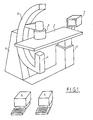
- the invention relates to a radiology installation comprising (FIG. 1) a table 1 of general position at least substantially horizontal, on which the body of a patient to be examined can rest, carried by table support means 2 which can be moved and locked, thanks to table drive means with locking and means for controlling the position of the table; a hoop 3, in particular isocentric, supporting at its two ends means of emission 4 of an X-ray beam and means of reception 5 (amplifier) of said beam, carried by hoop support means 6 movable and lockable by means of hoop drive means with locking and means for controlling the position of the hoop; means 7 for storing, processing, viewing images associated with the reception means, in particular by digital analysis, using a computer 8 for analyzing images; and a computer 9 associated with the means for controlling the position of the table and the roll bar and which can be connected to the computer 8.
- the transmission means 4 are generally located at the lower end of the hoop 3 and under the table 1 while the reception means 5 (amplifier) are generally located at the upper end of the hoop and above table 1 and, in operation of the installation, placed directly in contact with the patient resting on table 1 and this in the desired area.
- the table 1, and the hoop 3 and the transmission 4 and reception 5 means can be moved according to various combinable movements of sliding and / or rotation so as to be able to adjust the position of the X-ray beam relative to the table 1, not only with regard to the two axes (length and width) thereof - in particular for movement along the patient's body - but also in incidence.
- the reception means 5 (amplifier) are generally placed, in operation, in the immediate vicinity of the patient's body, as already indicated.
- the computer 8 allowing the digital analysis of the images and the computer 9 for the control of the table 1 and the roll bar 3 are the same or separate but are functionally connectable and / or structurally to each other. They naturally include the appropriate control means, the central unit, the peripherals, etc., and are loaded with the appropriate program or programs.
- the means 7 are shown in FIG. 1 as comprising one or more display screens. Naturally, they may include other temporary or permanent display means as well as means for storing the images obtained.
- the term "relative position" of the table 1 and of the hoop 3 designates a certain defined position of the table 1 and of the transmission 4 and reception 5 (amplifier) means, characterized by situations with respect to to the two axes of table 1, to the angles of incidence of the X-ray beam with respect to the upper plane P of table 1 (reference plane) as well as to the spacings in the vertical direction of the means 4, 5 with respect to the table 1.
- scale is meant, in the context of the present invention, the distance separating two image points on the screen of the means 7 compared to the real distance between the two origin points of the image.
- the relative positions in which the measurements are made are either taken at random, or correspond to conventional positions of investigation, or result from an increment of the parameters defining a position.
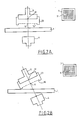
- step (ii) two opaque x-ray balls (lead) are placed in the center of the grid 10 and in the center of the amplifier 5 , 11 and 12 respectively, so that they are aligned and superimposed, the grid 10 being carried by a hanger 13 notably carried by the amplifier 5.
- the grid 10 is parallel to the plane of the amplifier 5, permanently .
- spacings between the center of the grid and on the one hand the plane of the amplifier 5 on the other hand the plane P of the table 1 are equal.
- An installation according to the invention is therefore characterized in that it also includes calibration means intended to know the coefficients of enlargement and distortion of the installation as well as the scale of the images obtained for the relative positions of the table and means of transmission and reception.
- the invention uses a computer 9 capable of performing the desired interpolations as well as the storage of the coefficients and scales for each position.
- This computer 9 is distinct or not from that 8 processing the images and / or controlling the relative displacements, but it is associated with it.
- the calibration thus described can be carried out originally before the first implementation of the installation and then checked at regular time intervals in order to ensure the consistency of the values obtained or, if necessary, the correct (especially in case of modification or replacement of the camera and / or its lens).
- the invention also provides that during the subsequent implementation of the installation, after calibration, the values of coefficients and scales are displayed on the screen of the means 7, during operation and this for any particular relative position of the table. 1 and the arch 3 as well as means 4, 5.
- This display can be instantaneous thanks to the calibration carried out beforehand, and thanks to the interface existing between the radiological installation and the computer 9.
- the practitioner can therefore, thanks to the invention, have immediate and precise knowledge of the real dimension of a stenosis as well as of healthy portions of the artery comprising this stenosis. He can therefore use the appropriate balloon, without risk of error, without the need for trial and error and without delay.
- the invention implies that at any time the relative position table 1-hoop 3 is known, which is made possible thanks to the computer 8 which is able, at any time on the one hand to know the relative position table 1 / hoop 3 /. means 4/5 /; and on the other hand controlling the relative displacements.
- the one hand means for displaying the parameters defining a relative position, in particular on the screen of the means 7, and, on the other hand, means for entering the desired values for the parameters defining a position relative such as a keyboard, or a mouse or a voice command induction system or the like.
- Appropriate computer software makes it possible to control the appropriate movements of the table 1 and of the hoop 3 as a function of an initial relative position and of the relative position thus defined.
- means are also provided for storing the parameters of a particular relative position, in particular repetitive.
- the parameters defining a relative table 1-hoop 3 position are as follows (FIG. 3): - Table height 1 (X) - Table position 1 antero posterior (Y) - Table 1 side position (Z) - Average reception height 5 (H) - Average reception rotation 5 ( ⁇ ) - Average reception angle 5 ( ⁇ ) - Field (C)
- each of these parameters and others, if any, may vary between extreme limits.
- the parameters corresponding to a dimension or an angle vary continuously.
- the field generally varies in a discrete way, being able to take some values (for example three).
- the values of the parameters correspond to adjustable levels of analog potentiometers POT of the drive means of table 1 and hoop 3.
- a suitable circuit allows the transmission to the computer used for the calibration of the values of the parameters corresponding to the relative position table 1-bar 3.
- This circuit can be the subject of numerous variant embodiments.
- it may include an amplification stage AMPLI for normalizing the voltage values of analog potentiometers already mentioned; a transmission circuit comprising the mixing of the MIX signals, an S / N sampler / switch, an analog / digital A / D converter, ending at the bottom of the computer 9 which includes a DATA BASE database making it possible to associate with specific values of the parameters of a relative position - that is to say at a determined relative position - the values of the coefficients of enlargement and distortion and the scale of the image. These values of the coefficients and this scale are obtained, as described, by interpolation from a few tested values.
- the invention is well suited to a real-time angioplasty procedure. Initially, when taking a picture, after injection of the contrast medium, the operator stores the image and the parameters defining the relative position of the radiological installation, and continues his examination by repeating this procedure a certain number of time. At the end of the examination, the operator recalls the images to choose those corresponding to the best incidence for performing the angioplasty. Thanks to the calibration process according to the invention, it can qualitatively measure the diameter of the artery in its healthy and steosed portions, by direct analysis of the image. Finally, the relative portions having been stored at the same time as the image, it can automatically reposition the installation in the position corresponding to the image acquisition position.
- the installation is well suited to an arterography procedure of the lower limbs in which an injection into the artery is carried out followed by a modification of the elementary relative position itself followed by an injection and 'another modification of the relative position and so on.
- an injection control computer in particular quantitatively in connection with the control computer for the relative positions.
- the software allowing the change of the relative positions according to instructions given by the operator comprises a security consisting in limiting the amplitude of the displacements according to limits corresponding to the morphology of the body of a patient on the table 1, so as to thus avoid any interference between the patient's body and the reception means 5.
- pressure sensors are provided on the reception means 5 so that when they are acted upon, which indicates an interference between the receiving means 5 and a fixed part: table 1 or body of the patient - the movements are stopped.
Landscapes
- Health & Medical Sciences (AREA)
- Life Sciences & Earth Sciences (AREA)
- Medical Informatics (AREA)
- Engineering & Computer Science (AREA)
- Radiology & Medical Imaging (AREA)
- Biomedical Technology (AREA)
- Biophysics (AREA)
- Nuclear Medicine, Radiotherapy & Molecular Imaging (AREA)
- Optics & Photonics (AREA)
- Pathology (AREA)
- Physics & Mathematics (AREA)
- High Energy & Nuclear Physics (AREA)
- Heart & Thoracic Surgery (AREA)
- Molecular Biology (AREA)
- Surgery (AREA)
- Animal Behavior & Ethology (AREA)
- General Health & Medical Sciences (AREA)
- Public Health (AREA)
- Veterinary Medicine (AREA)
- Apparatus For Radiation Diagnosis (AREA)
Abstract
Procédé de calibration numérique d'une installation de radiologie, comprenant une table (1), un arceau (3) supportant à ses deux extrémités des moyens d'émission (4) d'un faisceau de rayons X et des moyens de réception dudit faisceau (5), des moyens (7,8) de stockage, de traitement et de visualisation des images, et des moyens (9) pour commander les déplacements dans ladite installation. Une grille (10) calibrée, sert à évaluer les paramètres relatifs aux coefficients d'agrandissement et de distorsion de l'image réalisée. Lesdits paramètres sont transférés à un ordinateur (8) d'analyse d'images et à un ordinateur (9) commandant le positionnement de l'installation. 
Description
L'invention concerne un procédé de calibration numérique d'une installation de radiologie, plus spécialement destinée à des procédures d'angiographie et d'angioplastie et l'installation pour le mise en oeuvre de ce procédé.The invention relates to a method for digital calibration of a radiology installation, more specifically intended for angiography and angioplasty procedures and the installation for implementing this method.
On connaît déjà une installation de radiologie comprenant une table de position générale au moins sensiblement horizontale réglable et blocable, sur laquelle peut reposer le corps d'un patient à examiner ; un arceau, notamment isocentrique, supportant à ses deux extrémités des moyens d'émission d'un faisceau de rayons X (à l'extrémité inférieure au dessous de la table) et des moyens de réception du dit faisceau (à l'extrémité supérieure au dessus de la table et connus par l'homme du métier sous le nom d'amplificateur) également réglable et blocable; des moyens de stockage, traitement ; visualisation des images associés aux moyens de réception, notamment par analyse numérique des images produites, grâce en particulier à un ordinateur. Des moyens supports de la table et de l'arceau sont déplaçables et blocables grâce à des moyens d'entraînement et des moyens de commande.A radiology installation is already known comprising a general position table at least substantially horizontal adjustable and lockable, on which the body of a patient to be examined can rest; an arch, in particular isocentric, supporting at its two ends means for emitting an X-ray beam (at the lower end below the table) and means for receiving said beam (at the upper end at table top and known to those skilled in the art as an amplifier) also adjustable and lockable; means of storage, processing; display of the images associated with the reception means, in particular by digital analysis of the images produced, thanks in particular to a computer. Support means of the table and the roll bar are movable and lockable by means of drive and control means.
Avec une telle installation connue, on peut placer le corps d'un patient à examiner sur la table et régler la position de la table et/ou de l'arceau pour une certaine position relative correspondant à certains écartements et certains angles d'incidence et cela, selon les nécessités imposées par l'examen souhaité.With such a known installation, the body of a patient to be examined can be placed on the table and the position of the table and / or the roll bar can be adjusted to a certain relative position corresponding to certain spacings and certain angles of incidence and this, according to the necessities imposed by the desired examination.
Plusieurs développements ont été apportés récemment à ces installations. Tout d'abord la technique de numérisation des images a facilité la mise en oeuvre de l'installation en ce qui concerne le traitement de l'image. Ensuite, on a proposé d'automatiser les déplacements de la table et de l'arceau grâce à un ordinateur de commande (voir document FR 2 588 745).Several developments have been made recently to these installations. First of all, the image scanning technique facilitated the implementation of the installation with regard to image processing. Then, we proposed to automate the movements of the table and the roll bar thanks to a control computer (see document FR 2 588 745).
Par ailleurs récemment, se sont développées les procédures d'angioplastie consistant à repérer d'abord, sous contrôle angiographique, l'existence d'une sténose chez le patient puis à introduire dans l'artère à l'endroit de cette sténose un ballon de calibre approprié dont le gonflement, répété si nécessaire plusieurs fois, permet d'augmenter le calibre de l'artère.In addition, recently, angioplasty procedures have been developed which consist in first identifying, under angiographic control, the existence of a stenosis in the patient and then introducing a balloon into the artery at the location of this stenosis. appropriate caliber whose swelling, repeated if necessary several times, makes it possible to increase the caliber of the artery.
La bonne exécution de ces procédures d'angioplastie nécessiterait la connaissance rapide et précise des diamètres internes ou calibres de l'artère dans une portion saine et à l'endroit d'une sténose. En effet, en particulier, la taille du ballon à utiliser est fonction de ces diamètres internes.The proper execution of these angioplasty procedures would require rapid and precise knowledge of the internal diameters or calibers of the artery in a healthy portion and at the site of a stenosis. Indeed, in particular, the size of the balloon to be used is a function of these internal diameters.
Or, les installations de radiologie actuellement utilisées couramment, ne permettent qu'une appréciation relative des dimensions mais non leur connaissance absolue lors d'une lecture directe de l'image. Et cette connaissance des dimensions en valeur absolue est d'autant plus importante que les positions relatives table-arceau sont en nombre infini.However, the currently used radiology facilities allow only a relative appreciation of the dimensions but not their absolute knowledge during direct reading of the image. And this knowledge of dimensions in absolute value is all the more important as the relative table-arch positions are in infinite number.
L'invention a donc pour objet essentiel de permettre d'évaluer directement, à tout moment et pour toute position relative table-arceau, les dimensions exactes en valeur absolue de ce qui apparaît sur l'image obtenue.The essential object of the invention is therefore to allow direct evaluation, at any time and for any relative table-arch position, of the exact dimensions in absolute value of what appears on the image obtained.
La mesure technique proposée pour cet objet principal est l'étalonnage préalable de l'installation.The technical measure proposed for this main object is the prior calibration of the installation.
A cet effet, l'invention propose d'abord un procédé d'étalonnage d'une installation de radiologie, plus spécialement destinée à des procédures d'angiographie ou d'angioplastie, installation de radiologie comprenant une table de position générale au moins sensiblement horizontale, sur laquelle peut reposer le corps du patient à examiner, déplaçable et blocable ; un arceau notamment isocentrique supportant à ses deux extrémités des moyens d'émission d'un faisceau de rayons X et des moyen de réception du dit faisceau, déplaçables et blocables ; des moyens de stockage, traitement, visualisation d'images associés aux moyens de réception, notamment par analyse numérique des images produites, grâce à un ordinateur d'analyse des images ; et un ordinateur de réception et de commande des positions de la table et des moyens d'émission et réception reliés à l'ordinateur d'analyse des images ; procédures d'angiographie ou d'angioplastie dans lesquelles on place le corps d'un patient sur la table, on règle les positions relatives de la table et des moyens d'émission et de réception de rayons X (amplificateur), on met en oeuvre les moyens de stockage, traitement, visualisation d'images, caractérisé en ce qu' avant une procédure d'angiographie ou d'angioplastie et en l'absence d'un patient sur la table on étalonne l'installation de manière à connaître ses coefficients d'agrandissement et de distorsion et donc l'échelle des images obtenues, et à cet effet : pour les positions relatives de la table et des moyens d'émission et de réception :
- (i) On place la table et les moyens d'émission et de réception (amplificateur), dans une première position relative ;
- (ii) Dans cette première position relative, on interpose sur le faisceau de rayons X, une grille calibrée et opaque aux rayons X, dont le centre est aligné avec le centre de l'amplificateur, au moins sensiblement parallèlement au plan de l'amplificateur ; le centre de la grille se trouvant, dans cette première position relative de la table et de l'amplificateur à égale distance entre le plan de la table et le centre de l'amplificateur ;
- (iii) Dans cette première position relative et en présence de cette grille, on met en oeuvre les moyens de stockage, traitement, visualisation, un court moment pour obtenir une image de la grille ;
- (iv) On compare les dimensions et surfaces de la grille calibrée et de son image afin de connaître, pour cette première position relative, les coefficients d'agrandissement et de distorsion et l'échelle de l'image réalisée ;
- (v) On place ensuite la table et les moyens d'émission et de réception (amplificateur) dans une deuxième position relative différente de la première et pas trop éloignée ;
- (vi) Dans cette deuxième position relative, on règle, la cas échéant la position de la grille pour l'adapter si nécessaire -notamment on la déplace puis on la bloque en position- et on met également en oeuvre les moyens de stockage, traitement, visualisation, pour connaître, pour cette seconde position, les coefficients d'agrandissement et de distorsion et l'échelle de l'image réalisée ;
- (vii) On transmet à l'ordinateur les paramètres caractérisant en positions relatives de la table, des moyens d'émission et de réception (amplificateur) ainsi que les valeurs correspondantes des coefficients d'agrandissement et de distorsion et l'échelle.
- (viii) On interpole les coefficients d'agrandissements et de distorsion ainsi que l'échelle pour toute position relative intermédiaire comprise entre la première et la deuxième positions relatives lorsque nécessaire;
- (ix) On recommence les étapes précédentes pour d'autres positions relatives et les positions relatives intermédiaires souhaitées ;
- (x) On stocke les coefficients d'agrandissement et de distorsion les échelles et les paramètres caractérisant les différentes positions relatives, ainsi que les valeurs interpolées.
- (i) the table and the transmission and reception means (amplifier) are placed in a first relative position;
- (ii) In this first relative position, there is interposed on the X-ray beam, a calibrated grid opaque to X-rays, the center of which is aligned with the center of the amplifier, at least substantially parallel to the plane of the amplifier. ; the center of the grid being in this first relative position of the table and the amplifier at equal distance between the plane of the table and the center of the amplifier;
- (iii) In this first relative position and in the presence of this grid, the storage, processing, display means are used for a short time to obtain an image of the grid;
- (iv) The dimensions and surfaces of the calibrated grid and of its image are compared in order to know, for this first relative position, the coefficients of enlargement and distortion and the scale of the image produced;
- (v) The table and the transmission and reception means (amplifier) are then placed in a second relative position different from the first and not too far away;
- (vi) In this second relative position, the position of the grid is adjusted, if necessary, to adapt it if necessary -in particular, it is moved then it is locked in position- and the storage and processing means are also used. , display, to know, for this second position, the coefficients of enlargement and distortion and the scale of the image produced;
- (vii) The parameters characterizing in relative positions of the table, transmission and reception means (amplifier) as well as the corresponding values of the coefficients of enlargement and distortion and the scale are transmitted to the computer.
- (viii) The enlargement and distortion coefficients and the scale are interpolated for any intermediate relative position between the first and second relative positions when necessary;
- (ix) The preceding steps are repeated for other relative positions and the desired intermediate relative positions;
- (x) The enlargement and distortion coefficients are stored, the scales and the parameters characterizing the different relative positions, as well as the interpolated values.
L'invention propose ensuite une installation de radiologie, plus spécialement destinée à des procédures d'angiographie ou d'angioplastie, comprenant une table de position générale au moins sensiblement horizontale, sur laquelle peut reposer le corps du patient à examiner, portée des moyens supports de table déplaçables et blocables, grâce à des moyens d'entraînement de table avec blocage et des moyens de commande de la position de la table ; un arceau, notamment isocentrique, supportant à ses deux extrémités des moyens d'émission d'un faisceau de rayons X et des moyens de réception du dit faisceau, portés par des moyens support d'arceau déplaçables et blocables grâce à des moyens d'entraînement d'arceau avec blocage et des moyens de commande de la position de l'arceau ; des moyens de stockage, traitement, visualisation des images associés aux moyens de réception, notamment par analyse numérique, grâce à un ordinateur d'analyse des images; et un ordinateur associé aux moyens de commande de la position de la table et de l'arceau, caractérisé en ce qu'elle comporte également en premier lieu des moyens d'étalonnage destinés à connaître les coefficients d'agrandissement et de distorsion de l'installation ainsi que l'échelle des images obtenues pour les positions relatives de la table et des moyens d'émission et de réception ; et en second lieu, une interface apte à permettre à tout moment d'une part la transmission des valeurs numériques caractérisant toute position relative de la table et des moyens d'émission et de réception (amplificateur) et, d'autre part la commande des déplacements de la table et des moyens d'émission et de réception à partir d'instructions provenant de l'ordinateur.The invention then proposes a radiology installation, more specifically intended for angiography or angioplasty procedures, comprising a general position table at least substantially horizontal, on which the body of the patient to be examined can rest, carried by the support means movable and lockable table, thanks to drive means table with blocking and means for controlling the position of the table; an arch, in particular an isocentric arch, supporting at its two ends means for emitting an X-ray beam and means for receiving said beam, carried by movable arch support means which can be locked by means of drive means roll bar with blocking and means for controlling the position of the roll bar; means for storing, processing, viewing the images associated with the reception means, in particular by digital analysis, using a computer for analyzing the images; and a computer associated with the means for controlling the position of the table and the roll bar, characterized in that it also firstly comprises calibration means intended to know the coefficients of enlargement and of distortion of the installation as well as the scale of the images obtained for the relative positions of the table and of the transmission and reception means; and secondly, an interface able to allow at any time on the one hand the transmission of the digital values characterizing any relative position of the table and the transmission and reception means (amplifier) and, on the other hand the control of the movement of the table and of the transmission and reception means on the basis of instructions from the computer.
L'invention sera bien comprise grâce à la description qui suivra en référence aux dessins annexés dans lesquels :
- - La figure 1 est une vue purement schématique, en perspective d'une installation de radiologie selon l'invention.
- - La figure 2 est un schéma illustrant l'étalonnage selon l'invention.
- - La figure 3 est un des schémas possibles d'interface.
- - Figure 1 is a purely schematic view, in perspective of a radiology installation according to the invention.
- - Figure 2 is a diagram illustrating the calibration according to the invention.
- - Figure 3 is one of the possible interface diagrams.
L'invention concerne une installation de radiologie comportant (figure 1) une table 1 de position générale au moins sensiblement horizontale, sur laquelle peut reposer le corps d'un patient à examiner, portée des moyens supports de table 2 déplaçables et blocables, grâce à des moyens d'entraînement de table avec blocage et des moyens de commande de la position de la table ; un arceau 3, notamment isocentrique, supportant à ses deux extrémités des moyens d'émission 4 d'un faisceau de rayons X et des moyens de réception 5 (amplificateur) du dit faisceau, portés par des moyens support d'arceau 6 déplaçables et blocables grâce à des moyens d'entraînement d'arceau avec blocage et des moyens de commande de la position de l'arceau ; des moyens 7 de stockage, traitement, visualisation d'images associés aux moyens de réception, notamment par analyse numérique, grâce à un ordinateur 8 d'analyse d'images; et un ordinateur 9 associé aux moyens de commande de la position de la table et de l'arceau et pouvant être relié à l'ordinateur 8.The invention relates to a radiology installation comprising (FIG. 1) a table 1 of general position at least substantially horizontal, on which the body of a patient to be examined can rest, carried by table support means 2 which can be moved and locked, thanks to table drive means with locking and means for controlling the position of the table; a hoop 3, in particular isocentric, supporting at its two ends means of emission 4 of an X-ray beam and means of reception 5 (amplifier) of said beam, carried by hoop support means 6 movable and lockable by means of hoop drive means with locking and means for controlling the position of the hoop; means 7 for storing, processing, viewing images associated with the reception means, in particular by digital analysis, using a
Une telle installation ainsi qu'elle vient d'être décrite est parfaitement connue de l'homme du métier et pour cette raison ne nécessite pas d'explications supplémentaires détaillées. Cela est tout spécialement vrai pour les moyens support d'entraînement et de commande de la table et de l'arceau qui ne font pas en soi l'objet de l'invention. Les moyens d'émission 4 sont généralement situés à l'extrémité inférieure de l'arceau 3 et sous la table 1 tandis que les moyens de réception 5 (amplificateur) sont généralement situés à l'extrémité supérieure de l'arceau et au dessus de la table 1 et, en fonctionnement de l'installation, placés directement au contact du malade reposant sur la table 1 et cela dans la zone souhaitée. La table 1, et l'arceau 3 et les moyens d'émission 4 et de réception 5 peuvent être déplacés selon divers mouvements combinables de coulissement et/ou rotation de manière à pouvoir régler la position du faisceau de rayons X par rapport à la table 1, non seulement en ce qui concerne les deux axes (longueur et largeur) de celle-ci -notamment pour un déplacement le long du corps du patient- mais aussi en incidence.Such an installation as just described is perfectly known to those skilled in the art and for this reason does not require any further detailed explanations. This is especially true for the support means for driving and controlling the table and the hoop which are not in themselves the subject of the invention. The transmission means 4 are generally located at the lower end of the hoop 3 and under the table 1 while the reception means 5 (amplifier) are generally located at the upper end of the hoop and above table 1 and, in operation of the installation, placed directly in contact with the patient resting on table 1 and this in the desired area. The table 1, and the hoop 3 and the transmission 4 and reception 5 means can be moved according to various combinable movements of sliding and / or rotation so as to be able to adjust the position of the X-ray beam relative to the table 1, not only with regard to the two axes (length and width) thereof - in particular for movement along the patient's body - but also in incidence.
De façon également connue en soi, les moyens de réception 5 (amplificateur) sont généralement placés, en fonctionnement, à proximité immédiate du corps du patient, ainsi que déjà indiqué.In a manner also known per se, the reception means 5 (amplifier) are generally placed, in operation, in the immediate vicinity of the patient's body, as already indicated.
L'ordinateur 8 permettant l'analyse numérique des images et l'ordinateur 9 pour la commande de la table 1 et de l'arceau 3 sont les mêmes ou distincts mais sont reliables fonctionnellement et/ou structurellement l'un à l'autre. Ils comportent naturellement les moyens de commande, l'unité centrale, les périphériques etc..., appropriés et sont chargés avec le ou les programmes convenables.The
Les moyens 7 sont représentés sur la figure 1 comme comprenant un ou plusieurs écran(s) de visualisation. Naturellement, ils peuvent comporter d'autres moyens de visualisation temporaires ou permanente ainsi que des moyens de stockage des images obtenues.The
Par la suite on désigne par "position relative" de la table 1 et de l'arceau 3, une certaine position définie de la table 1 et des moyens d'émission 4 et de réception 5 (amplificateur), caractérisée par des situations par rapport aux deux axes de la table 1, aux angles d'incidence du faisceau de rayons X par rapport au plan supérieur P de la table 1 (plan de référence) ainsi qu'aux écartements en sens vertical des moyens 4, 5 par rapport à la table 1.Subsequently, the term "relative position" of the table 1 and of the hoop 3 designates a certain defined position of the table 1 and of the transmission 4 and reception 5 (amplifier) means, characterized by situations with respect to to the two axes of table 1, to the angles of incidence of the X-ray beam with respect to the upper plane P of table 1 (reference plane) as well as to the spacings in the vertical direction of the means 4, 5 with respect to the table 1.
On comprend que ces positions relatives sont en nombre illimité et que pour chacune d'elles il y a une certaine valeur du coefficient d'agrandissement et de distorsion ainsi qu'une certaine échelle.It is understood that these relative positions are in unlimited number and that for each of them there is a certain value of the coefficient of enlargement and distortion as well as a certain scale.
On entend par échelle, dans le contexte de la présente invention, la distance séparant deux points images sur l'écran des moyens 7 comparativement à la distance réelle entre les deux points origines de l'image. Par exemple le diamètre de l'image d'une artère par rapport au diamètre effectif de l'artère elle-même.By scale is meant, in the context of the present invention, the distance separating two image points on the screen of the
Selon le procédé d'étalonnage suivant l'invention de l'installation de radiologie ainsi définie, avant une procédure d'angiographie ou d'angioplastie et en l'absence d'un patient sur la table 1 on étalonne l'installation de manière à connaître ses coefficients d'agrandissement et de distorsion et donc l'échelle des images obtenues, et, à cet effet : pour les positions relatives de la table 1 et des moyens d'émission et de réception 4, 5:
- (i) On place la table 1 et les moyens d'émission et de réception 4, 5, dans une première position relative ;
- (ii) Dans cette première position relative, on interpose sur le faisceau de rayons X, une
grille 10 calibrée et opaque aux rayons X, dont le centre est aligné avec le centre de l'amplificateur, au moins sensiblement parallèlement au plan de l'amplificateur ; le centre de la grille se trouvant, dans cette première position relative de la table et de l'amplificateur à égale distance entre le plan de la table et le centre de l'amplificateur ; - (iii) Dans cette première position relative et en présence de cette
grille 10, on met en oeuvre les moyens d'émission et de réception 4, 5 et lesmoyens 7 de stockage, traitement, visualisation, un court moment pour obtenir une image de lagrille 10; - (iv) On compare les dimensions et surfaces de la
grille 10 calibrée et de son image afin de connaître, pour cette première position relative, les coefficients d'agrandissement et de distorsion et l'échelle de l'image réalisée ; - (v) On place ensuite la table 1 et les moyens d'émission et de réception 4, 5 dans une deuxième position relative différente de la première et pas trop éloignée ;
- (vi) Dans cette deuxième position relative, on règle la position de la
grille 10 pour l'adapter et on met également en oeuvre les moyens d'émission et de réception 4, 5 et les moyens 7 de stockage, traitement, visualisation, pour connaître, pour cette seconde position, les coefficients d'agrandissement et de distorsion et l'échelle de l'image réalisée et cela conformément à la procédure déjà décrite; - (vii) On transmet à l'ordinateur les paramètres caractérisant en positions relatives de la table, des moyens d'émission et de réception (amplificateur) ainsi que les valeurs correspondantes des coefficients d'agrandissement et de distorsion et l'échelle.
- (viii) On interpole les coefficients d'agrandissements et de distorsion ainsi que l'échelle pour toute position relative intermédiaire comprise entre la première et la deuxième positions relatives lorsque nécessaire;
- (ix) On recommence les étapes précédentes pour d'autres positions relatives et les positions relatives intermédiaires souhaitées ;
- (x) On stocke les coefficients d'agrandissement et de distorsion, les échelles et les paramètres caractérisant les différentes positions relatives, ainsi que les valeurs interpolées.
- (i) The table 1 and the transmission and reception means 4, 5 are placed in a first relative position;
- (ii) In this first relative position, there is interposed on the X-ray beam, a
grid 10 calibrated and opaque to X-rays, the center of which is aligned with the center of the amplifier, at least substantially parallel to the plane of the amplifier ; the center of the grid being in this first relative position of the table and the amplifier at equal distance between the plane of the table and the center of the amplifier; - (iii) In this first relative position and in the presence of this
grid 10, the transmission and reception means 4, 5 and the storage means 7, processing, display are used, a short time to obtain an image ofgrid 10; - (iv) The dimensions and surfaces of the calibrated
grid 10 and of its image are compared in order to know, for this first relative position, the coefficients of enlargement and distortion and the scale of the image produced; - (v) Then placing the table 1 and the transmission and reception means 4, 5 in a second relative position different from the first and not too far away;
- (vi) In this second relative position, the position of the
grid 10 is adjusted to adapt it and the transmission and reception means 4, 5 and the storage, processing, display means are also used to knowing, for this second position, the coefficients of enlargement and distortion and the scale of the image produced and this in accordance with the procedure already described; - (vii) The parameters characterizing in relative positions of the table, transmission means and reception (amplifier) as well as the corresponding values of the coefficients of enlargement and distortion and the scale.
- (viii) The enlargement and distortion coefficients and the scale are interpolated for any intermediate relative position between the first and second relative positions when necessary;
- (ix) The preceding steps are repeated for other relative positions and the desired intermediate relative positions;
- (x) The enlargement and distortion coefficients, the scales and the parameters characterizing the different relative positions are stored, as well as the interpolated values.
Les positions relatives dans lesquelles sont faites les mesures sont soit prises au hasard, soit correspondent à des positions classiques d'investigation, soit découlent d'une incrèmentation des paramètres définissant une position.The relative positions in which the measurements are made are either taken at random, or correspond to conventional positions of investigation, or result from an increment of the parameters defining a position.
L'écart entre deux positions relatives dans lesquelles une mesure est faite est à la portée de l'homme du métier en fonction notamment des moyens de calcul mis en oeuvre pour l'interpolation, de la précision souhaitée pour les calculs des valeurs par interpolation, de l'importance de la variation des coefficients et échelles recherchés par rapport à la variation des paramètres définissant les positions.The difference between two relative positions in which a measurement is made is within the reach of those skilled in the art depending in particular on the calculation means used for the interpolation, on the precision desired for the calculations of the values by interpolation, the importance of the variation of the coefficients and scales sought compared to the variation of the parameters defining the positions.
Pour interposer la grille 10, ainsi qu'il est prévu à l'étape (ii), on met en place, au centre de la grille 10 et au centre de l'amplificateur 5, deux billes opaques aux rayons X (en plomb), 11 et 12 respectivement, pour qu'elles soient alignées et superposées, la grille 10 étant portée par une suspente 13 notamment portée par l'amplificateur 5. De cette manière la grille 10 est parallèle au plan de l'amplificateur 5, en permanence. De plus, (voir figure 2B plus spécialement) les écartements entre le centre de la grille et d'une part le plan de l'amplificateur 5 d'autre part le plan P de la table 1 sont égaux.To interpose the
Une installation selon l'invention est donc caractérisée en ce qu'elle comporte également des moyens d'étalonnage destinés à connaître les coefficients d'agrandissement et de distorsion de l'installation ainsi que l'échelle des images obtenues pour les positions relatives de la table et des moyens d'émission et de réception.An installation according to the invention is therefore characterized in that it also includes calibration means intended to know the coefficients of enlargement and distortion of the installation as well as the scale of the images obtained for the relative positions of the table and means of transmission and reception.
Préférentiellement l'invention met en oeuvre un ordinateur 9 apte à effectuer les interpolations souhaitées ainsi que le stockage des coefficients et échelles pour chaque position. Cet ordinateur 9 est distinct ou non de celui 8 traitant les images et / ou commandant les déplacements relatifs mais il lui est associé.Preferably, the invention uses a
Il est à noter que l'étalonnage ainsi décrit peut être réalisé originellement avant la première mise en oeuvre de l'installation et ensuite vérifiée à intervalles de temps réguliers afin de s'assurer de la constance des valeurs obtenues ou, le cas échéant, les corriger (notamment en cas de modifications ou de remplacement de la caméra et / ou de son objectif).It should be noted that the calibration thus described can be carried out originally before the first implementation of the installation and then checked at regular time intervals in order to ensure the consistency of the values obtained or, if necessary, the correct (especially in case of modification or replacement of the camera and / or its lens).
L'invention prévoit également que lors de la mise en oeuvre ultérieure de l'installation, après étalonnage, les valeurs de coefficients et échelles soient affichés sur l'écran des moyens 7, lors du fonctionnement et cela pour toute position particulière relative de la table 1 et de l'arceau 3 ainsi que des moyens 4, 5. Cet affichage peut être instantané grâce à l'étalonnage réalisé préalablement, et grâce à l'interface existant entre l'installation radiologique et l'ordinateur 9.The invention also provides that during the subsequent implementation of the installation, after calibration, the values of coefficients and scales are displayed on the screen of the
Dans le cas d'une angioplastie, le praticien peut donc, grâce à l'invention, avoir une connaissance immédiate et précise de la dimension réelle d'une sténose ainsi que de portions saines de l'artère comprenant cette sténose. Il peut donc utiliser le ballon approprié, sans risque d'erreur, sans nécessité de tâtonnements et sans délai.In the case of angioplasty, the practitioner can therefore, thanks to the invention, have immediate and precise knowledge of the real dimension of a stenosis as well as of healthy portions of the artery comprising this stenosis. He can therefore use the appropriate balloon, without risk of error, without the need for trial and error and without delay.
Naturellement l'invention implique qu'à tout moment la position relative table 1-arceau 3 soit connue, ce qui est rendu possible grâce à l'ordinateur 8 lequel est en mesure, à tout instant d'une part de connaitre la position relative table 1 / arceau 3 / . moyens 4/ 5/ ;et d'autre part commander les déplacements relatifs. Généralement, il est prévu d'une part des moyens d'affichage des paramètres définissant une position relative, notamment sur l'écran des moyens 7, et, d'autre part, des moyens de saisie des valeurs souhaitées pour les paramètres définissant une position relative tels qu'un clavier, ou une souris ou un système d'induction vocale de commande ou autre-. Un logiciel approprié de l'ordinateur permet de commander les déplacements convenables de la table 1 et de l'arceau 3 en fonction d'une position relative initiale et de la position relative ainsi définie.Naturally the invention implies that at any time the relative position table 1-hoop 3 is known, which is made possible thanks to the
Le cas échéant, il est également prévu des moyens de stockage des paramètres d'une position relative particulière, notamment répétitive.Where appropriate, means are also provided for storing the parameters of a particular relative position, in particular repetitive.
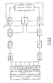
Selon une variante possible de mise en oeuvre de l'invention, les paramètres définissant une position relative table 1-arceau 3 sont les suivants (figure 3) :
- Hauteur table 1 (X)
- Position table 1 antéro postérieure (Y)
- Position table 1 latérale (Z)
- Hauteur moyen réception 5 (H)
- Rotation moyen réception 5 (β)
- Angulation moyen réception 5 (γ)
- Champ (C)According to a possible variant implementation of the invention, the parameters defining a relative table 1-hoop 3 position are as follows (FIG. 3):
- Table height 1 (X)
-
- Table 1 side position (Z)
- Average reception height 5 (H)
- Average reception rotation 5 (β)
- Average reception angle 5 (γ)
- Field (C)
Chacun de ces paramètres ainsi que d'autres, éventuels peut varier entre des bornes extrêmes. Les paramètres correspondant à une dimension ou un angle varient de façon continue. Le champ varie généralement de façon discrète, pouvant prendre quelques valeurs (par exemple trois).Each of these parameters and others, if any, may vary between extreme limits. The parameters corresponding to a dimension or an angle vary continuously. The field generally varies in a discrete way, being able to take some values (for example three).
Les valeurs des paramètres correspondent à des niveaux réglables de potentiomètres analogiques POT des moyens d'entraînement de la table 1 et de l'arceau 3.The values of the parameters correspond to adjustable levels of analog potentiometers POT of the drive means of table 1 and hoop 3.
Un circuit approprié permet la transmission à l'ordinateur utilisé pour l'étalonnage des valeurs des paramètres correspondant à la position relative table 1-arceau 3.A suitable circuit allows the transmission to the computer used for the calibration of the values of the parameters corresponding to the relative position table 1-bar 3.
Ce circuit peut faire l'object de nombreuses variantes de réalisation. Par exemple si on se réfère expressement à la figue 3 il peut comporter un étage d'amplification AMPLI permettant de normaliser les valeurs de tension de potentiomètres analogiques déjà mentionnés ; un circuit de transmission comportant le mixage des signaux MIX , un échantillonneur/interrupteur S/N ,un convertisseur analogique/digital A/D, aboutissant au bas de l'ordinateur 9 lequel comporte une base de données DATA BASE permettant d'associer à des valeurs spécifiques des paramètres d'une position relative -c'est-à-dire à une position relative déterminée- les valeurs des coefficients d'agrandissement et de distorsion et l'échelle de l'image. Ces valeurs des coefficients et cette échelle sont obtenus, ainsi que décrit, par interpolation à partir de quelques valeurs testées.This circuit can be the subject of numerous variant embodiments. For example if we refer expressly to fig 3 it may include an amplification stage AMPLI for normalizing the voltage values of analog potentiometers already mentioned; a transmission circuit comprising the mixing of the MIX signals, an S / N sampler / switch, an analog / digital A / D converter, ending at the bottom of the
Selon une autre caractéristique, l'invention est bien adaptée à une procédure d'angioplastie en temps réel. Initalement, lors de la prise d'un cliché, après injection du produit de contraste, l'opérateur stocke l'image et les paramètres définissant la position relative de l'installation radiologique, et continue son examen en répétant cette procédure un certain nombre de fois. A la fin de l'examen, l'opérateur rappelle les images pour choisir celles correspondant à la meilleure incidence pour effectuer l'angioplastie. Grâce au procédé d'étalonnage selon l'invention, il peut mesurer qualitativement le diamètre de l'artère dans ses portions saines et steosées, par analyse directe de l'image. Enfin, les portions relatives ayant été stockées en même temps que l'image, il peut repositionner automatiquement l'installation dans la position correspondant à la position d'acquisition de l'image.According to another characteristic, the invention is well suited to a real-time angioplasty procedure. Initially, when taking a picture, after injection of the contrast medium, the operator stores the image and the parameters defining the relative position of the radiological installation, and continues his examination by repeating this procedure a certain number of time. At the end of the examination, the operator recalls the images to choose those corresponding to the best incidence for performing the angioplasty. Thanks to the calibration process according to the invention, it can qualitatively measure the diameter of the artery in its healthy and steosed portions, by direct analysis of the image. Finally, the relative portions having been stored at the same time as the image, it can automatically reposition the installation in the position corresponding to the image acquisition position.
Selon une autre caractéristique, l' installation est bien adaptée à une procédure d'artérographie des membres inférieurs dans laquelle on effectue une injection dans l'artère suivie d'une modification de la position relative élémentaire elle-même suivie d'un injection et d'une autre modification de la position relative et ainsi de suite. Dans ce cas, il est possible, également, de prévoir un ordinateur de commande des injections (notamment quantativement) en liaison avec l'ordinateur de commande des positions relatives.According to another characteristic, the installation is well suited to an arterography procedure of the lower limbs in which an injection into the artery is carried out followed by a modification of the elementary relative position itself followed by an injection and 'another modification of the relative position and so on. In this case, it is also possible to provide an injection control computer (in particular quantitatively) in connection with the control computer for the relative positions.
Selon une autre caractéristique, le logiciel permettant le changement des positions relatives selon des instructions données par l'opérateur comporte une sécurité consistant à limiter l'amplitude des déplacements selon des bornes correspondant à la morphologie du corps d'un patient sur la table 1, de manière à éviter ainsi toute interférence entre le corps du patient et les moyens de réception 5. De plus, des capteurs de pression sont prévus sur les moyens de réception 5 de telle manière que lorsqu'ils sont sollicités -ce qui indique une interférence entre les moyens de réception 5 et une partie fixe : table 1 ou corps du patient- les déplacements soient stoppés.According to another characteristic, the software allowing the change of the relative positions according to instructions given by the operator comprises a security consisting in limiting the amplitude of the displacements according to limits corresponding to the morphology of the body of a patient on the table 1, so as to thus avoid any interference between the patient's body and the reception means 5. In addition, pressure sensors are provided on the reception means 5 so that when they are acted upon, which indicates an interference between the receiving means 5 and a fixed part: table 1 or body of the patient - the movements are stopped.
Claims (3)
Applications Claiming Priority (2)
| Application Number | Priority Date | Filing Date | Title |
|---|---|---|---|
| IT2070588 | 1988-05-24 | ||
| IT20705/88A IT1217701B (en) | 1988-05-24 | 1988-05-24 | NUMERICAL CALIBRATION PROCEDURE FOR INSTALLATION OF RADIOLOGY AND INSTALLATION OF NUMERICAL CALIBRATION FOR THE IMPLEMENTATION OF THE PROCEDURE |
Publications (1)
| Publication Number | Publication Date |
|---|---|
| EP0343600A1 true EP0343600A1 (en) | 1989-11-29 |
Family
ID=11170829
Family Applications (1)
| Application Number | Title | Priority Date | Filing Date |
|---|---|---|---|
| EP89109274A Withdrawn EP0343600A1 (en) | 1988-05-24 | 1989-05-23 | Method and device for digital calibration of an X-ray installation |
Country Status (3)
| Country | Link |
|---|---|
| EP (1) | EP0343600A1 (en) |
| IL (1) | IL90376A0 (en) |
| IT (1) | IT1217701B (en) |
Cited By (6)
| Publication number | Priority date | Publication date | Assignee | Title |
|---|---|---|---|---|
| EP0627198A1 (en) * | 1993-03-12 | 1994-12-07 | Koninklijke Philips Electronics N.V. | X-ray examination apparatus |
| US5483572A (en) * | 1993-03-12 | 1996-01-09 | U.S. Philips Corporation | X-ray examination apparatus |
| WO2001000092A1 (en) * | 1999-06-25 | 2001-01-04 | Ddi Direct Digital Imaging Gmbh | Digital x-ray scanning apparatus |
| FR2848806A1 (en) * | 2002-12-18 | 2004-06-25 | Ge Med Sys Global Tech Co Llc | METHOD FOR CALIBRATING A RADIOLOGICAL IMAGING APPARATUS REQUIRING A LIMITED NUMBER OF ACQUISITIONS |
| WO2005119174A1 (en) * | 2004-05-26 | 2005-12-15 | Werth Messtechnik Gmbh | Coordinate measuring apparatus and method for measuring an object |
| DE102009015144A1 (en) | 2009-03-26 | 2010-09-30 | Siemens Aktiengesellschaft | Method for obtaining mapping rule of point in three dimensional space on image plane for X-ray image recoding system, involves utilizing mapping rule for defining basic value set, where rule is delivered for positioning interpolation values |
Citations (5)
| Publication number | Priority date | Publication date | Assignee | Title |
|---|---|---|---|---|
| FR2115423A1 (en) * | 1970-11-27 | 1972-07-07 | Varian Associates | |
| US3887804A (en) * | 1973-12-03 | 1975-06-03 | Us Health | Radiographic test stand |
| DE2716818A1 (en) * | 1976-04-19 | 1977-11-03 | Varian Associates | TOMOGRAPHY SYSTEM |
| WO1980001111A1 (en) * | 1978-11-24 | 1980-05-29 | Kermath Mfg Corp | Tomographic method and apparatus |
| DE8612533U1 (en) * | 1986-05-07 | 1987-09-17 | Siemens AG, 1000 Berlin und 8000 München | X-ray diagnostic device |
-
1988
- 1988-05-24 IT IT20705/88A patent/IT1217701B/en active
-
1989
- 1989-05-23 IL IL90376A patent/IL90376A0/en unknown
- 1989-05-23 EP EP89109274A patent/EP0343600A1/en not_active Withdrawn
Patent Citations (5)
| Publication number | Priority date | Publication date | Assignee | Title |
|---|---|---|---|---|
| FR2115423A1 (en) * | 1970-11-27 | 1972-07-07 | Varian Associates | |
| US3887804A (en) * | 1973-12-03 | 1975-06-03 | Us Health | Radiographic test stand |
| DE2716818A1 (en) * | 1976-04-19 | 1977-11-03 | Varian Associates | TOMOGRAPHY SYSTEM |
| WO1980001111A1 (en) * | 1978-11-24 | 1980-05-29 | Kermath Mfg Corp | Tomographic method and apparatus |
| DE8612533U1 (en) * | 1986-05-07 | 1987-09-17 | Siemens AG, 1000 Berlin und 8000 München | X-ray diagnostic device |
Cited By (9)
| Publication number | Priority date | Publication date | Assignee | Title |
|---|---|---|---|---|
| EP0627198A1 (en) * | 1993-03-12 | 1994-12-07 | Koninklijke Philips Electronics N.V. | X-ray examination apparatus |
| US5483572A (en) * | 1993-03-12 | 1996-01-09 | U.S. Philips Corporation | X-ray examination apparatus |
| WO2001000092A1 (en) * | 1999-06-25 | 2001-01-04 | Ddi Direct Digital Imaging Gmbh | Digital x-ray scanning apparatus |
| JP2003503095A (en) * | 1999-06-25 | 2003-01-28 | ディーディーアイ・ダイレクト・デジタル・イメージング・ゲーエムベーハー | Digital X-ray scanner |
| FR2848806A1 (en) * | 2002-12-18 | 2004-06-25 | Ge Med Sys Global Tech Co Llc | METHOD FOR CALIBRATING A RADIOLOGICAL IMAGING APPARATUS REQUIRING A LIMITED NUMBER OF ACQUISITIONS |
| JP2004195234A (en) * | 2002-12-18 | 2004-07-15 | Ge Medical Systems Global Technology Co Llc | Method and device for calibration of radiation image pickup device |
| US7066646B2 (en) | 2002-12-18 | 2006-06-27 | Ge Medical Systems Global Technology Company, Llc | Process and apparatus for calibration of a radiological imaging device |
| WO2005119174A1 (en) * | 2004-05-26 | 2005-12-15 | Werth Messtechnik Gmbh | Coordinate measuring apparatus and method for measuring an object |
| DE102009015144A1 (en) | 2009-03-26 | 2010-09-30 | Siemens Aktiengesellschaft | Method for obtaining mapping rule of point in three dimensional space on image plane for X-ray image recoding system, involves utilizing mapping rule for defining basic value set, where rule is delivered for positioning interpolation values |
Also Published As
| Publication number | Publication date |
|---|---|
| IT1217701B (en) | 1990-03-30 |
| IT8820705A0 (en) | 1988-05-24 |
| IL90376A0 (en) | 1989-12-15 |
Similar Documents
| Publication | Publication Date | Title |
|---|---|---|
| CA1052014A (en) | Installation for inspecting and examining fuel rods of a nuclear reactor | |
| JP2805318B2 (en) | Device for determining the contour of the cornea of the human eye | |
| US20030067595A1 (en) | Automatic measurement of the modulation transfer function of an optical system | |
| FR2602602A1 (en) | VIEW IMAGE CORRECTION DEVICE AND METHOD FOR MOVING AN OBJECT | |
| EP2065695B1 (en) | Method for analysing a scratching test | |
| EP0459853A1 (en) | Acquisition method of echography images | |
| US8508591B2 (en) | System and method for estimating the height of an object using tomosynthesis-like techniques | |
| EP0360653A1 (en) | Method and system for correcting image defects caused by the movement of a scanner | |
| EP1246565A1 (en) | Device for evaluating a position of balance for the human body | |
| FR2631810A1 (en) | METHOD FOR THE DIGITAL CALIBRATION OF A RADIOLOGY FACILITY AND DIGITAL CALIBRATION FACILITY FOR THE IMPLEMENTATION OF THE METHOD | |
| EP0018872B1 (en) | Method and apparatus for tomographic density evaluation | |
| EP0343600A1 (en) | Method and device for digital calibration of an X-ray installation | |
| WO1990012277A1 (en) | Process and device for large-scale profilometric measurement and their application to the measurement of the condition of surfaces irrespective of shape | |
| JP4374753B2 (en) | X-ray CT system | |
| EP1103221B1 (en) | Methods and apparatus for optimizing CT image quality with optimized data acquisition | |
| FR2881941A1 (en) | METHOD FOR DETERMINING THE GEOMETRIC PARAMETERS OF AN X-RAY IMAGING DEVICE | |
| JP2535712B2 (en) | X-ray CT system | |
| WO2015155466A1 (en) | Measurement device for correcting parasitic movements in an x-ray tomograph | |
| JP2007215698A (en) | X-ray ct apparatus | |
| KR20090041656A (en) | Physical Phantom and Compensation Method Using the Same | |
| FR2700039A1 (en) | Maintenance of low level of artifacts in tomographic image | |
| FR2932373A1 (en) | Bone part's i.e. pelvis, angle and/or length measuring method for installing intramedullary prosthesis, involves measuring angle and/or length at given scale using goniometer, and displaying values of measured angle and length on LCD | |
| FR2737005A1 (en) | METHOD FOR THE GEOMETRIC CALIBRATION OF AN IMAGING APPARATUS | |
| US6418185B1 (en) | Methods and apparatus for time-multiplexing data acquisition | |
| EP0689048B1 (en) | Method for the obtention of the image of an object rotating around an axis by means of tangential radiography |
Legal Events
| Date | Code | Title | Description |
|---|---|---|---|
| PUAI | Public reference made under article 153(3) epc to a published international application that has entered the european phase |
Free format text: ORIGINAL CODE: 0009012 |
|
| AK | Designated contracting states |
Kind code of ref document: A1 Designated state(s): AT BE CH DE ES GB GR LI LU NL SE |
|
| 17P | Request for examination filed |
Effective date: 19900511 |
|
| STAA | Information on the status of an ep patent application or granted ep patent |
Free format text: STATUS: THE APPLICATION HAS BEEN WITHDRAWN |
|
| 18W | Application withdrawn |
Withdrawal date: 19920121 |