EP0343481A2 - Device and method for controlling brushless four-phase DC motors - Google Patents
Device and method for controlling brushless four-phase DC motors Download PDFInfo
- Publication number
- EP0343481A2 EP0343481A2 EP19890108717 EP89108717A EP0343481A2 EP 0343481 A2 EP0343481 A2 EP 0343481A2 EP 19890108717 EP19890108717 EP 19890108717 EP 89108717 A EP89108717 A EP 89108717A EP 0343481 A2 EP0343481 A2 EP 0343481A2
- Authority
- EP
- European Patent Office
- Prior art keywords
- switches
- closed
- open
- switch
- control device
- Prior art date
- Legal status (The legal status is an assumption and is not a legal conclusion. Google has not performed a legal analysis and makes no representation as to the accuracy of the status listed.)
- Withdrawn
Links
Images


Classifications
-
- H—ELECTRICITY
- H02—GENERATION; CONVERSION OR DISTRIBUTION OF ELECTRIC POWER
- H02K—DYNAMO-ELECTRIC MACHINES
- H02K29/00—Motors or generators having non-mechanical commutating devices, e.g. discharge tubes or semiconductor devices
- H02K29/06—Motors or generators having non-mechanical commutating devices, e.g. discharge tubes or semiconductor devices with position sensing devices
- H02K29/08—Motors or generators having non-mechanical commutating devices, e.g. discharge tubes or semiconductor devices with position sensing devices using magnetic effect devices, e.g. Hall-plates, magneto-resistors
-
- H—ELECTRICITY
- H02—GENERATION; CONVERSION OR DISTRIBUTION OF ELECTRIC POWER
- H02P—CONTROL OR REGULATION OF ELECTRIC MOTORS, ELECTRIC GENERATORS OR DYNAMO-ELECTRIC CONVERTERS; CONTROLLING TRANSFORMERS, REACTORS OR CHOKE COILS
- H02P6/00—Arrangements for controlling synchronous motors or other dynamo-electric motors using electronic commutation dependent on the rotor position; Electronic commutators therefor
- H02P6/14—Electronic commutators
Definitions
- the invention relates to a device and a method for controlling brushless, in particular 4-strand DC motors.
- the rotating fields required for converting electrical into mechanical energy by means of electric motors can be generated mechanically (brushes in connection with collectors attached to the rotor) or electronically using semiconductor switches.
- a brushless DC motor is known from US Pat. No. 4,484,115, the stator of which is wound with a 7-strand winding in star or ring connection.
- the rotor of the DC motor is covered with permanent magnets.
- the current required to generate a rotating field is controlled with the aid of semiconductor switches, for the control of which a position sensor which detects the rotor position is used. Two semiconductor switches are assigned to each winding phase to enable bipolar operation.
- the brushless direct current motor described in the US patent has the disadvantage that a pair of complementary transistors is required for its control per line. This is a complex and costly solution.
- the brushless DC motor according to DE-PS 33 01 801 has the disadvantage that the stator winding strands are connected in a star connection. With this switching of the stator winding, the stator cannot be wound fully automatically, and soldering work is also required on the winding heads. In addition, with such a stator winding, the end windings become quite large in the axial direction, which leads to additional electrical losses.
- the object of the invention is to provide an inexpensive and largely automatically manufactured brushless DC motor and a method for its control. This object is achieved by a DC motor with the combination of features of the first device claim and by a method with the features of the method claims.
- the brushless DC motor according to the invention has the advantage that only four semiconductor switches are required to control its four strands. Another advantage is that the stator winding is connected in a ring circuit. In this way, the stator can be wound fully automatically. Soldering on the winding heads are not required and the entire winding is shorter in the axial direction than conventional stator windings. Another advantage is the fact that the DC motor can be controlled with several switching sequences.
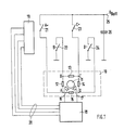
- Fig. 1 shows the basic structure of a control circuit for a 4-strand brushless DC motor, the stator winding is connected in a ring circuit. 1 contains all the elements that belong to the DC motor and not to the control circuit.
- 11 denotes a rotor covered with permanent magnetic material, 12, 13, 14 and 15 identify the four strands of the stator.
- 16 and 17 denote two magnetic field sensors which detect the position of the rotor 11. The two sensors 16 and 17 are connected to a commutation circuit 18.
- the output of the commutation circuit 18 is connected to a driver circuit 19 via lines labeled 20.
- 21 denotes a switch A+, 22 a switch B ⁇ , 23 a switch C+ and 24 a switch D ⁇ .
- the two switches A+ and C+ connect points A and C on the motor to the supply voltage.
- the switches B ⁇ and D ⁇ connect the points B and D to the ground.
- 25 a connection for the supply voltage is designated, with 26 a smoothing capacitor.
- FIG. 2 serves to explain the switching sequence of the arrangement according to FIG. 1 with simple commutation.
- the circle labeled 30 schematically identifies a stator of a brushless DC motor wound with four winding strands connected in a ring circuit.
- the points denoted by A, B, C and D correspond to the points A, B, C and D in FIG. 1.
- the arrows marked 31 in the circumferential direction show the direction of current flow in the individual strands in the respective switching state of the semiconductor switches.
- 32 denotes a flow vector resulting from this current distribution.
- a filled connection point A, B, C or D stands for the connection of this point with the supply voltage or with the ground.
- Second step switches A+ and D ⁇ are closed, the flow vector rotates 90 o further.
- Fourth step switches C+ and B ⁇ are closed, switches A+ and D ⁇ open.
- the first step is started again. It can be seen from the flow arrows in FIG. 2, designated 32, that a switching field is generated by this switching sequence, which drives the rotor of the machine.
- the flow pattern shown here refers to a two-pole machine in which an electrical angle of 2 pi corresponds to a machine angle of 2 pi. With a higher number of pole pairs and the same control sequence, the rotor rotates by an electrical angle of 2 Pi or by a spatial angle of 2 Pi / p with p equal to the number of poles of the motor.
- FIG. 1 The arrangement according to FIG. 1 can, however, be controlled in a different way.
- a Switching sequence hereinafter referred to as double commutation, is described with the aid of FIG. 3.
- the number of the schematically represented motors in the top line of FIG. 3 is twice as large as in FIG. 2.
- the designations of the connections, the current flow in the individual lines and the resulting flow vector are as in FIG. 2.
- First step switches A+ and B ⁇ closed, switches C+ and D ⁇ open
- second step switches A+, B ⁇ and D ⁇ closed, switch C+ open
- third step switches A+ and D ⁇ closed, switches C+ and B ⁇ open
- fourth step switches A+, C+ and D ⁇ closed, switch B ⁇ open
- fifth step switches C+ and D ⁇ closed, switches A+ and B ⁇ open
- sixth step switches C+, B ⁇ and D ⁇ closed, switch A+ open
- seventh step switches C+ and B ⁇ closed, switches A+ and D ⁇ open
- Eighth step switches A+, C+ and B ⁇ closed, switch D ⁇ open.
Abstract
Description
Die Erfindung betrifft eine Vorrichtung und ein Verfahren zur Steuerung von bürstenlosen, insbesondere 4-strängigen Gleichstrommotoren.The invention relates to a device and a method for controlling brushless, in particular 4-strand DC motors.
Die zur Umwandlung elektrischer in mechanische Energie mittels Elektromotoren erforderlichen Drehfelder lassen sich mechanisch (Bürsten in Verbindung mit auf dem Rotor angebrachten Kollektoren) oder elektronisch mit Hilfe von Halbleiterschaltern erzeugen. Aus der US-PS 4,484,115 ist ein bürstenloser Gleichstrommotor bekannt, dessen Stator mit einer 7-strängigen Wicklung in Stern- oder Ringschaltung gewickelt ist. Der Rotor des Gleichstrommotors ist mit Permanentmagneten belegt. Der zur Erzeugung eines Drehfeldes erforderliche Strom wird mit Hilfe von Halbleiterschaltern gesteuert, zu deren Ansteuerung ein die Rotorstellung detektierender Positionssensor dient. Jedem Wicklungsstrang sind je zwei Halbleiterschalter zugeordnet, um bipolaren Betrieb zu ermöglichen.The rotating fields required for converting electrical into mechanical energy by means of electric motors can be generated mechanically (brushes in connection with collectors attached to the rotor) or electronically using semiconductor switches. A brushless DC motor is known from US Pat. No. 4,484,115, the stator of which is wound with a 7-strand winding in star or ring connection. The rotor of the DC motor is covered with permanent magnets. The current required to generate a rotating field is controlled with the aid of semiconductor switches, for the control of which a position sensor which detects the rotor position is used. Two semiconductor switches are assigned to each winding phase to enable bipolar operation.
Aus der DE-PS 33 01 801 ist weiterhin bekannt, einen bürstenlosen 4-strängigen Gleichstrommotor in Sternschaltung mit nur vier Halbleiterschaltern anstelle von acht Halbleiterschaltern bipolar zu betreiben.From DE-PS 33 01 801 it is also known to operate a brushless 4-strand DC motor in star connection with only four semiconductor switches instead of eight semiconductor switches in bipolar fashion.
Der in der US-Patentschrift beschriebene bürstenlose Gleichstrommotor hat den Nachteil, daß zu seiner Ansteuerung pro Strang je ein Paar komplementärer Transistoren erforderlich ist. Dies ist somit eine aufwendige und kostspielige Lösung. Der bürstenlose Gleichstrommotor entsprechend der DE-PS 33 01 801 hat den Nachteil, daß die Ständerwicklungsstränge in Sternschaltung miteinander verschaltet sind. Bei dieser Schaltung der Ständerwicklung läßt sich der Ständer nicht vollautomatisch wickeln, außerdem sind an den Wickelköpfen Lötarbeiten erforderlich. Darüberhinaus werden bei einer solchen Ständerwicklung die Wickelköpfe in axialer Richtung ziemlich groß, was zu zusätzlichen elektrischen Verlusten führt.The brushless direct current motor described in the US patent has the disadvantage that a pair of complementary transistors is required for its control per line. This is a complex and costly solution. The brushless DC motor according to DE-PS 33 01 801 has the disadvantage that the stator winding strands are connected in a star connection. With this switching of the stator winding, the stator cannot be wound fully automatically, and soldering work is also required on the winding heads. In addition, with such a stator winding, the end windings become quite large in the axial direction, which leads to additional electrical losses.
Aufgabe der Erfindung ist es, einen preisgünstigen und weitgehend automatisch herstellbaren bürstenlosen Gleichstrommotor und ein Verfahren zu seiner Ansteuerung anzugeben. Diese Aufgabe wird gelöst durch einen Gleichstrommotor mit der Merkmalskombination des ersten Vorrichtungsanspruches sowie durch ein Verfahren mit den Merkmalen der Verfahrensansprüche.The object of the invention is to provide an inexpensive and largely automatically manufactured brushless DC motor and a method for its control. This object is achieved by a DC motor with the combination of features of the first device claim and by a method with the features of the method claims.
Der erfindungsgemäße bürstenlose Gleichstrommotor hat den Vorteil, daß zur Ansteuerung seiner vier Stränge lediglich vier Halbleiterschalter erforderlich sind. Ein weiterer Vorteil liegt darin, daß die Statorwicklung in Ringschaltung geschaltet ist. Der Stator kann auf diese Weise vollautomatisch bewickelt werden. Lötarbeiten an den Wickelköpfen sind nicht erforderlich und die gesamte Wicklung wird in axialer Richtung kürzer als übliche Statorwicklungen. Ein weiterer Vorteil ist darin zu sehen, daß der Gleichstrommotor mit mehreren Schaltsequenzen angesteuert werden kann.The brushless DC motor according to the invention has the advantage that only four semiconductor switches are required to control its four strands. Another advantage is that the stator winding is connected in a ring circuit. In this way, the stator can be wound fully automatically. Soldering on the winding heads are not required and the entire winding is shorter in the axial direction than conventional stator windings. Another advantage is the fact that the DC motor can be controlled with several switching sequences.
Ein Ausführungsbeispiel der Erfindung wird im folgenden beschrieben und anhand der Figuren 1 bis 3 näher erläutert. Es zeigen:
- Fig. 1 den prinzipiellen Aufbau einer Ansteuerschaltung für einen 4-strängigen, bürstenlosen Gleichstrommotor; Statorwicklung in Ringschaltung,
- Fig. 2 Schaltzustände der vier Halbleiterschalter und Stellung des Durchflutungsvektors bei einfacher Kommutierung pro Umlauf und Polpaarzahl,
- Fig. 3 Schaltzustände der vier Halbleiterschalter und Stellung des Durchflutungsvektors bei doppelter Kommutierung pro Umlauf und Polpaarzahl.
- Figure 1 shows the basic structure of a control circuit for a 4-strand, brushless DC motor. Stator winding in ring circuit,
- 2 switching states of the four semiconductor switches and position of the flow vector with simple commutation per revolution and number of pole pairs,
- Fig. 3 switching states of the four semiconductor switches and position of the flow vector with double commutation per revolution and number of pole pairs.
Fig. 1 zeigt den prinzipellen Aufbau einer Ansteuerschaltung für einen 4-strängigen bürstenlosen Gleichstrommotor, dessen Statorwicklung in Ringschaltung geschaltet ist. In einem mit 10 bezeichneten Teilbereich der Fig. 1 sind alle die Elemente enthalten, die zum Gleichstrommotor und nicht zur Ansteuerschaltung gehören. 11 kennzeichnet einen mit permanentmagnetischem Material belegten Rotor, 12, 13, 14 und 15 kennzeichnen die vier Stränge des Stators. Mit 16 und 17 sind zwei Magnetfeldsensoren bezeichnet, die die Stellung des Rotors 11 detektieren. Die beiden Sensoren 16 und 17 sind mit einer Kommutierungsschaltung 18 verbunden. Der Ausgang der Kommutierungsschaltung 18 ist über mit 20 bezeichnete Leitungen mit einer Treiberschaltung 19 verbunden. 21 bezeichnet einen Schalter A⁺, 22 einen Schalter B⁻, 23 einen Schalter C⁺ und 24 einen Schalter D⁻. Die beiden Schalter A⁺ und C⁺ verbinden die Punkte A und C am Motor mit der Versorgungsspannung. Die Schalter B⁻ und D⁻ verbinden die Punkte B und D mit der Masse. Mit 25 ist ein Anschluß für die Versorgungsspannung bezeichnet, mit 26 ein Glättungskondensator.Fig. 1 shows the basic structure of a control circuit for a 4-strand brushless DC motor, the stator winding is connected in a ring circuit. 1 contains all the elements that belong to the DC motor and not to the control circuit. 11 denotes a rotor covered with permanent magnetic material, 12, 13, 14 and 15 identify the four strands of the stator. 16 and 17 denote two magnetic field sensors which detect the position of the
Fig. 2 dient zur Erläuterung der Schaltsequenz der Anordnung nach Fig. 1 bei einfacher Kommutierung. Der mit 30 bezeichnete Kreis kennzeichnet schematisch einen mit vier in Ringschaltung zusammengeschalteten Wicklungsträngen bewickelten Stator eines bürstenlosen Gleichstrommotors. Die mit A, B, C und D bezeichneten Punkte entsprechen den Punkten A, B, C und D in Fig. 1. Die mit 31 gekennzeichneten Pfeile in Umfangsrichtung geben die Stromflußrichtung in den einzelnen Strängen bei dem jeweiligen Schaltzustand der Halbleiterschalter wieder. Mit 32 ist ein aus dieser Stromverteilung resultierender Durchflutungsvektor bezeichnet. Ein ausgefüllter Anschlußpunkt A, B, C oder D steht für die Verbindung dieses Punktes mit der Versorgungsspannung bzw. mit der Masse.FIG. 2 serves to explain the switching sequence of the arrangement according to FIG. 1 with simple commutation. The circle labeled 30 schematically identifies a stator of a brushless DC motor wound with four winding strands connected in a ring circuit. The points denoted by A, B, C and D correspond to the points A, B, C and D in FIG. 1. The arrows marked 31 in the circumferential direction show the direction of current flow in the individual strands in the respective switching state of the semiconductor switches. 32 denotes a flow vector resulting from this current distribution. A filled connection point A, B, C or D stands for the connection of this point with the supply voltage or with the ground.
Ein schwarzer Punkt bedeutet also stets, daß der entsprechende Halbleiterschalter geschlossen ist. Unterhalb der Zeile mit den Motoren 30 ist das Schema für die Schalterstellungen, bezogen auf einen elektrischen Winkel von 2 Pi, wiedergegeben. Schraffierte Flächen geben an, daß der entsprechende Schalter in diesem Winkelbereich geschlossen ist. Damit ergibt sich folgende Schaltsequenz: Erster Schritt: Die Schalter A⁺ und B⁻ sind geschlossen, die Schalter C⁺ und D⁻ offen. Eine aus den Strängen 13, 14 und 15 gebildete Serienschaltung liegt elektrisch parallel zum Strang 12. Die so entstehende Durchflutung erzeugt in Verbindung mit dem mit permanentmagnetischem Material belegten Rotor ein Drehmoment, welches dazu führt, daß sich der Rotor weiterdreht.A black dot therefore always means that the corresponding semiconductor switch is closed. Below the line with the
Zweiter Schritt: Die Schalter A⁺ und D⁻ sind geschlossen, der Durchflutungsvektor dreht sich um 90o weiter.Second step: switches A⁺ and D⁻ are closed, the flow vector rotates 90 o further.
Dritter Schritt: Die Schalter C⁺ und D⁻ sind geschlossen, die Schalter A⁺ und B⁻ offen. Wieder dreht sich der Durchflutungsvektor um einen Winkel von 90o in mathematisch positiver Richtung.Third step: switches C⁺ and D⁻ are closed, switches A⁺ and B⁻ open. Again the flow vector rotates through an angle of 90 o in the mathematically positive direction.
Vierter Schritt: Die Schalter C⁺ und B⁻ sind geschlossen, die Schalter A⁺ und D⁻ offen. Nach Durchlaufen der gesamten Sequenz wird wieder beim ersten Schritt begonnen. An den mit 32 bezeichneten Durchflutungspfeilen in Fig. 2 erkennt man, daß durch diese Schaltsequenz ein Drehfeld erzeugt wird, welches den Rotor der Maschine antreibt. Der hier dargestellte Durchflutungsverlauf bezieht sich auf eine zweipolige Maschine, bei welcher ein elektrischer Winkel von 2 Pi einem Maschinenwinkel von 2 Pi entspricht. Bei höherer Polpaarzahl und gleicher Steuersequenz dreht sich der Rotor um einen elektrischen Winkel von 2 Pi oder um einen räumlichen Winkel von 2 Pi/p mit p gleich der Polzahl des Motors.Fourth step: switches C⁺ and B⁻ are closed, switches A⁺ and D⁻ open. After running through the entire sequence, the first step is started again. It can be seen from the flow arrows in FIG. 2, designated 32, that a switching field is generated by this switching sequence, which drives the rotor of the machine. The flow pattern shown here refers to a two-pole machine in which an electrical angle of 2 pi corresponds to a machine angle of 2 pi. With a higher number of pole pairs and the same control sequence, the rotor rotates by an electrical angle of 2 Pi or by a spatial angle of 2 Pi / p with p equal to the number of poles of the motor.
Die Anordnung nach Fig. 1 kann jedoch noch in einer anderen Art und Weise angesteuert werden. Eine Schaltsequenz, im folgenden doppelte Kommutierung genannt, wird mit Hilfe von Fig. 3 beschrieben. Die Zahl der schematisch dargestellten Motoren in der obersten Zeile von Fig. 3 ist doppelt so groß wie in Fig. 2. Bezeichnungen der Anschlüsse, des Stromflusses in den einzelnen Strängen und des resultierenden Durchflutungsvektors sind wie in Fig. 2. Aus dem darunter befindlichen Diagramm liest man die Schaltsequenz wie folgt ab:
Erster Schritt: Schalter A⁺ und B⁻ geschlossen, Schalter C⁺ und D⁻ offen,
zweiter Schritt: Schalter A⁺, B⁻ und D⁻ geschlossen, Schalter C⁺ offen,
dritter Schritt: Schalter A⁺ und D⁻ geschlossen, Schalter C⁺ und B⁻ offen,
vierter Schritt: Schalter A⁺, C⁺ und D⁻ geschlossen, Schalter B⁻ offen,
fünfter Schritt: Schalter C⁺ und D⁻ geschlossen, Schalter A⁺ und B⁻ offen,
sechster Schritt: Schalter C⁺, B⁻ und D⁻ geschlossen, Schalter A⁺ offen,
siebter Schritt: Schalter C⁺ und B⁻ geschlossen, Schalter A⁺ und D⁻ offen,
achter Schritt: Schalter A⁺, C⁺ und B⁻ geschlossen, Schalter D⁻ offen.The arrangement according to FIG. 1 can, however, be controlled in a different way. A Switching sequence, hereinafter referred to as double commutation, is described with the aid of FIG. 3. The number of the schematically represented motors in the top line of FIG. 3 is twice as large as in FIG. 2. The designations of the connections, the current flow in the individual lines and the resulting flow vector are as in FIG. 2. From the diagram below you can read the switching sequence as follows:
First step: switches A⁺ and B⁻ closed, switches C⁺ and D⁻ open,
second step: switches A⁺, B⁻ and D⁻ closed, switch C⁺ open,
third step: switches A⁺ and D⁻ closed, switches C⁺ and B⁻ open,
fourth step: switches A⁺, C⁺ and D⁻ closed, switch B⁻ open,
fifth step: switches C⁺ and D⁻ closed, switches A⁺ and B⁻ open,
sixth step: switches C⁺, B⁻ and D⁻ closed, switch A⁺ open,
seventh step: switches C⁺ and B⁻ closed, switches A⁺ and D⁻ open,
Eighth step: switches A⁺, C⁺ and B⁻ closed, switch D⁻ open.
Nach Durchlaufen dieser Sequenz wird wieder mit dem ersten Schritt begonnen.After running through this sequence, the first step is started again.
Vergleicht man die in Fig. 2 und Fig. 3 beschriebenen Schaltsequenzen miteinander, so sieht man, daß es in der Schaltsequenz nach Fig. 3, der doppelten Kommutierung, Schaltzustände gibt, in denen drei Schalter geschlossen sind. In der Schaltsequenz nach Fig. 2 sind immer nur zwei Schalter geschlossen. Mit beiden Schaltsequenzen wird auf elektronischem Wege ein Drehfeld erzeugt.If one compares the switching sequences described in FIGS. 2 and 3 with one another, it can be seen that there are switching states in the switching sequence according to FIG. 3, double commutation, in which three switches are closed. In the switching sequence according to FIG. 2, only two switches are ever closed. With both switching sequences, a rotating field is generated electronically.
Auf eine detaillierte Beschreibung des Aufbaus der Statorwicklung sowie auf eine Beschreibung der Einzelheiten der Kommutierungslogik 18 und der Treiberschaltungen 19 wird an dieser Stelle verzichtet, da sie nicht Gegenstand der Erfindung sind.A detailed description of the structure of the stator winding and a description of the details of the
Claims (9)
dadurch gekennzeichnet, daß die vier Stränge der Ankerwicklung in Ringschaltung zusammengeschaltet sind und jeder zwischen je zwei Strängen liegende Verbindungspunkt mit einem Schaltelement verbunden ist.1. Control device for the bipolar control of the stator of a 4-strand brushless DC motor, the rotor of which is occupied by at least one pole pair of a permanent magnetic material, with sensors for detecting the rotor position and with four switching elements that can be switched depending on the signals from the sensors,
characterized in that the four strands of the armature winding are connected in a ring circuit and each connection point lying between two strands is connected to a switching element.
Applications Claiming Priority (2)
| Application Number | Priority Date | Filing Date | Title |
|---|---|---|---|
| DE3817423A DE3817423A1 (en) | 1988-05-21 | 1988-05-21 | DEVICE AND METHOD FOR CONTROLLING BRUSHLESS, 4-STRING DC MOTORS |
| DE3817423 | 1988-05-21 |
Publications (2)
| Publication Number | Publication Date |
|---|---|
| EP0343481A2 true EP0343481A2 (en) | 1989-11-29 |
| EP0343481A3 EP0343481A3 (en) | 1990-05-23 |
Family
ID=6354902
Family Applications (1)
| Application Number | Title | Priority Date | Filing Date |
|---|---|---|---|
| EP89108717A Withdrawn EP0343481A3 (en) | 1988-05-21 | 1989-05-16 | Device and method for controlling brushless four-phase dc motors |
Country Status (4)
| Country | Link |
|---|---|
| US (1) | US5043641A (en) |
| EP (1) | EP0343481A3 (en) |
| JP (1) | JPH0223088A (en) |
| DE (1) | DE3817423A1 (en) |
Cited By (1)
| Publication number | Priority date | Publication date | Assignee | Title |
|---|---|---|---|---|
| WO2005095765A1 (en) * | 2004-03-26 | 2005-10-13 | Schaeffler Kg | Electric camshaft adjuster comprising a pancake motor |
Families Citing this family (6)
| Publication number | Priority date | Publication date | Assignee | Title |
|---|---|---|---|---|
| US5737210A (en) * | 1996-04-30 | 1998-04-07 | Magnetek, Inc. | Bridge rectifier configuration and mounting for supplying exciter current in an AC generator |
| WO2003042999A1 (en) * | 2001-11-10 | 2003-05-22 | Robert Bosch Gmbh | Electronically commutated motor |
| KR100725758B1 (en) * | 2004-03-30 | 2007-06-08 | 삼성광주전자 주식회사 | An electric blower and a supercharger for an automobile |
| KR20050105315A (en) * | 2004-04-28 | 2005-11-04 | 엘지전자 주식회사 | Control circuit for ice transfer device in refrigerator |
| FR2901927B1 (en) * | 2006-06-01 | 2014-07-04 | Valeo Equip Electr Moteur | THREE-PHASE ELECTRIC ROTATING MACHINE |
| DE102018201340B3 (en) * | 2018-01-30 | 2019-06-13 | Bayerische Motoren Werke Aktiengesellschaft | Method for operating a rotating field machine of a motor vehicle, transmission device, drive unit and motor vehicle |
Citations (2)
| Publication number | Priority date | Publication date | Assignee | Title |
|---|---|---|---|---|
| US3831072A (en) * | 1972-02-21 | 1974-08-20 | Canon Kk | Dc motor with hall generators |
| US4484115A (en) * | 1981-07-14 | 1984-11-20 | Fuji Photo Film Co., Ltd. | Brushless motor |
Family Cites Families (8)
| Publication number | Priority date | Publication date | Assignee | Title |
|---|---|---|---|---|
| JPS5851790A (en) * | 1981-09-19 | 1983-03-26 | Victor Co Of Japan Ltd | Dc brushless motor |
| JPS58127586A (en) * | 1982-01-22 | 1983-07-29 | Victor Co Of Japan Ltd | Dc commutatorless motor |
| US4689532A (en) * | 1985-05-07 | 1987-08-25 | Howlett James F | Ferritic sensor, self-controlled synchronous motor |
| DE3528765A1 (en) * | 1985-08-10 | 1987-02-19 | Bosch Gmbh Robert | CIRCUIT ARRANGEMENT FOR A BRUSHLESS DC MOTOR |
| NL8503249A (en) * | 1985-11-26 | 1987-06-16 | Philips Nv | BRUSHLESS DC MOTOR. |
| US4703235A (en) * | 1986-12-03 | 1987-10-27 | United Technologies Corporation | Brushless DC motor |
| DE3710659A1 (en) * | 1987-03-31 | 1988-10-13 | Standard Elektrik Lorenz Ag | ELECTRONICALLY COMMUTED, COLLECTORLESS DC MOTOR |
| DE3710658A1 (en) * | 1987-03-31 | 1988-10-13 | Standard Elektrik Lorenz Ag | ELECTRONICALLY COMMUTED, COLLECTORLESS DC MOTOR |
-
1988
- 1988-05-21 DE DE3817423A patent/DE3817423A1/en not_active Withdrawn
-
1989
- 1989-04-13 US US07/337,482 patent/US5043641A/en not_active Expired - Fee Related
- 1989-05-16 EP EP89108717A patent/EP0343481A3/en not_active Withdrawn
- 1989-05-22 JP JP1128619A patent/JPH0223088A/en active Pending
Patent Citations (2)
| Publication number | Priority date | Publication date | Assignee | Title |
|---|---|---|---|---|
| US3831072A (en) * | 1972-02-21 | 1974-08-20 | Canon Kk | Dc motor with hall generators |
| US4484115A (en) * | 1981-07-14 | 1984-11-20 | Fuji Photo Film Co., Ltd. | Brushless motor |
Non-Patent Citations (1)
| Title |
|---|
| ELEKTRONIK. Band 34, Nr. 22, 31 Oktober 1985, Seiten 92-98, München, DE; KMETZ J.: "Bürstenloser Gleichtrommotor elektronisch angesteuert". * |
Cited By (1)
| Publication number | Priority date | Publication date | Assignee | Title |
|---|---|---|---|---|
| WO2005095765A1 (en) * | 2004-03-26 | 2005-10-13 | Schaeffler Kg | Electric camshaft adjuster comprising a pancake motor |
Also Published As
| Publication number | Publication date |
|---|---|
| EP0343481A3 (en) | 1990-05-23 |
| JPH0223088A (en) | 1990-01-25 |
| DE3817423A1 (en) | 1989-11-23 |
| US5043641A (en) | 1991-08-27 |
Similar Documents
| Publication | Publication Date | Title |
|---|---|---|
| DE3812638C2 (en) | Brushless bipolar multi-phase DC motor | |
| DE3490616C2 (en) | ||
| DE60007878T2 (en) | CONTROL OF AN ELECTRICAL RELUCTIVE MACHINE | |
| DE69916476T2 (en) | SYNCHRONOUS MACHINE WITH ROTATING BRUSHES | |
| DE3233096A1 (en) | ELECTRONICALLY COMMUTED MOTOR, WASHING MACHINE, METHOD FOR OPERATING THE SAME, CONTROL CIRCUIT AND WASHING MACHINE DRIVE | |
| DE102005014664A1 (en) | Electric machine | |
| DE1964229A1 (en) | Brushless DC motor | |
| DE2527744A1 (en) | ELECTRONICALLY COMMUTED MOTOR AND PROCESS FOR ITS MANUFACTURING | |
| DE2305163A1 (en) | BRUSHLESS DC MOTOR | |
| DE10319394A1 (en) | Switched reluctance machine, especially SR motor | |
| DE4025713A1 (en) | POWER SWITCH MOTOR | |
| EP0150070A2 (en) | Commutatorless direct-current motor with a ironless stator winding | |
| DE102004030460B3 (en) | Drive motor for electric or hybrid vehicle using free-running diodes of commutation control for supplying braking energy of motor to supply current source | |
| EP0343481A2 (en) | Device and method for controlling brushless four-phase DC motors | |
| DE19722453C1 (en) | Electrical power drive system | |
| DE102020122142A1 (en) | A BRUSHLESS DC DYNAMO AND A VEHICLE WITH THE BRUSHLESS DC DYNAMO | |
| EP0664599B1 (en) | Commutator motor | |
| DE60203657T2 (en) | Unit consisting of electromagnetic brake and its electrical supply | |
| DE4330386A1 (en) | Switched reluctance motor | |
| DE1638569A1 (en) | Brushless direct current miniature motor with permanent magnet excited rotor | |
| DE3218740C2 (en) | ||
| DE7310863U (en) | COLLECTORLESS DC MOTOR | |
| EP1758229A2 (en) | Electric motor | |
| DE1538893A1 (en) | Brushless universal motor | |
| AT383916B (en) | DC MOTOR WITH PERMANENT MAGNETIC ROTOR AND ELECTRONIC COMMUTING CIRCUIT |
Legal Events
| Date | Code | Title | Description |
|---|---|---|---|
| PUAI | Public reference made under article 153(3) epc to a published international application that has entered the european phase |
Free format text: ORIGINAL CODE: 0009012 |
|
| AK | Designated contracting states |
Kind code of ref document: A2 Designated state(s): CH DE ES GB IT LI |
|
| PUAL | Search report despatched |
Free format text: ORIGINAL CODE: 0009013 |
|
| AK | Designated contracting states |
Kind code of ref document: A3 Designated state(s): CH DE ES GB IT LI |
|
| 17P | Request for examination filed |
Effective date: 19900925 |
|
| RAP3 | Party data changed (applicant data changed or rights of an application transferred) |
Owner name: ALCATEL SEL AKTIENGESELLSCHAFT |
|
| 17Q | First examination report despatched |
Effective date: 19921120 |
|
| STAA | Information on the status of an ep patent application or granted ep patent |
Free format text: STATUS: THE APPLICATION HAS BEEN WITHDRAWN |
|
| 18W | Application withdrawn |
Withdrawal date: 19930428 |