EP0343401A2 - Investment casting mould - Google Patents
Investment casting mould Download PDFInfo
- Publication number
- EP0343401A2 EP0343401A2 EP89107893A EP89107893A EP0343401A2 EP 0343401 A2 EP0343401 A2 EP 0343401A2 EP 89107893 A EP89107893 A EP 89107893A EP 89107893 A EP89107893 A EP 89107893A EP 0343401 A2 EP0343401 A2 EP 0343401A2
- Authority
- EP
- European Patent Office
- Prior art keywords
- alumina
- slurry
- mould
- pattern
- firing
- Prior art date
- Legal status (The legal status is an assumption and is not a legal conclusion. Google has not performed a legal analysis and makes no representation as to the accuracy of the status listed.)
- Withdrawn
Links
Images
Classifications
-
- B—PERFORMING OPERATIONS; TRANSPORTING
- B22—CASTING; POWDER METALLURGY
- B22C—FOUNDRY MOULDING
- B22C1/00—Compositions of refractory mould or core materials; Grain structures thereof; Chemical or physical features in the formation or manufacture of moulds
- B22C1/16—Compositions of refractory mould or core materials; Grain structures thereof; Chemical or physical features in the formation or manufacture of moulds characterised by the use of binding agents; Mixtures of binding agents
- B22C1/165—Compositions of refractory mould or core materials; Grain structures thereof; Chemical or physical features in the formation or manufacture of moulds characterised by the use of binding agents; Mixtures of binding agents in the manufacture of multilayered shell moulds
-
- B—PERFORMING OPERATIONS; TRANSPORTING
- B22—CASTING; POWDER METALLURGY
- B22C—FOUNDRY MOULDING
- B22C9/00—Moulds or cores; Moulding processes
- B22C9/02—Sand moulds or like moulds for shaped castings
- B22C9/04—Use of lost patterns
Definitions
- the present invention relates to a mould and to a method for the manufacture of moulds for investment casting.
- known ceramic moulds are adequate for the casting of components with microstructures of equiaxed grains. Where the components are required to be of directionally solidified, columnar grain structure (DS) or of single crystal structure (SX), however, known mould materials have certain disadvantages.
- the casting procedure for the production of DS and SX components requires that the mould be maintained for several hours above the liquidus temperature of the alloy being cast. Such temperatures may exceed 1500 o C. At these temperatures the strength and stiffness of the mould may be inadequate to withstand the prolonged metallostatic pressure of the molten alloy without either rupture or unacceptable distortion. This limitation is primarily associated with viscous creep of the siliceous binder phase.
- An object of the present invention is to provide a mould having improved high temperature strength and creep resistance than known moulds.
- a method for the the manufacture of a ceramic shell mould comprises the steps of making a slurry comprising colloidal silica having alumina flour therein, coating a pattern of a component to be cast with the slurry, dusting the coated pattern with alumina particles, drying the coated and dusted pattern, dipping the pattern into a slurry for a second time, repeatting with alumina particles and drying again, repeating the slurry dipping, dusting and drying stages at least one further time, removing the pattern and then firing the shell mould.
- a "flour” is defined as a ceramic powder wherein substantially all particles are less than 100 micro metres in diameter.
- the dried shell mould so formed is fired at a temperature sufficiently high to allow at least a part of the silica to combine with the alumina flour. to form mullite (3Al2O3.2SiO2) in the matrix binder phase.
- the shell may be fired either in a specific firing operation after drying and removal of the pattern or during preheating and "soaking" of the mould prior to the casting operation. Temperatures in excess of 1400 o C are preferred.
- the alumina in the slurry should be in the form generally known as "reactive alumina".
- alumina has a high specific surface area and a very small particle size.
- suitable commercially available alumina powders are those of the "RA” series (trademark) produced by British Alcan Aluminium Limited and those by Alcoa under the code CT9 (trade mark).
- the slurry may contain from 1 to 25 wt% of reactive alumina and up to 70 wt% of other alumina flour. More preferably the matrix slurry may contain from 10 to 20 wt% of reactive alumina.
- the matrix slurry may optionally contain up to 5 wt% of fine titania powder which may act as a catalyst in the formation of mullite in the matrix. It has been found that additions greater than 5 wt% confer no additional practical benefit.
- a ceramic shell mould when made by the method of the first aspect.
- the new mould material possesses greater thermal diffusivity than conventional materials. This is advantageous, especially in the case of DS and SX castings in that it allows more precise control of heat extraction thereby reducing the risk of nucleating stray grains in the so-called "mushy" region ahead of the solidification front.
- a further advantage conferred by the greatly improved high temperature strength properties of the new material is that thinner shell moulds may be used. This in turn also enhances control of heat extraction during solidification.
- Shell moulds of the present invention contain only synthetic "starting" materials which are both readily available and of relatively high purity compared to naturally occuring minerals such as zircon.
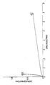
- the accompanying figure shows a graph of creep displacement against time for conventional mould materials and for materials according to the present invention.
- Moulds for testing were prepared by the following method.
- a wax pattern was dipped in a slurry of the first composition shown in Table 1.
- the dipped pattern was then dusted with 80's mesh (B.S.) fused alumina and dried.
- the coated pattern was then dipped in a more dilute version of the same slurry and then dusted with 28/48's mesh (B.S.) Tabular Alumina and then dried.
- the sample was then dipped in a slurry of the second composition given in Table 1, dusted with 28/48's mesh (B.S.) Tabular Alumina and dried.
- the final stage in building the shell mould was a slurry dip only followed by drying.
- Each sample had seven slurry and six dusting coats.
- the wax pattern was removed by a known method.
- the colloidal silica contained approximately 30 wt% of silica.
- the strength of the A2 material under equivalent processing conditions is about 60% greater than the Y.D.S material and the A2′ material is 100% stronger than the Y.D.S. material.
- the important improvement of the A2′ material over the Y.D.S material is in creep resistance as shown by the creep tests in the accompanying figure. Conditions for the tests were; test temperature 1420 o C; test bars fired at 1500 o for approximately 2 hours and soaked at the test temperatures for approximately 6 minutes prior to testing; test bar section was 4.6 x 25.0 mm and a 750g static load was used.
- the conventional Y.D.S. material failed in under 20 seconds with a displacement of 0.6 mm whereas the A2′ material showed steady creep with a displacement of 0.33 mm after 7 minutes. In casting DS and SX components creep resistance of the shell mould is of greater importance.
- the thermal diffusivity of the A2 and A2′ materials was 4.24 mm2 sec ⁇ 1 compared with 1.74 mm2 sec ⁇ 1 for the Y.D.S. material.
- Mullite was detected by X-ray diffraction analysis in A2′ but not in A2 material.
Landscapes
- Engineering & Computer Science (AREA)
- Mechanical Engineering (AREA)
- Chemical & Material Sciences (AREA)
- Materials Engineering (AREA)
- Mold Materials And Core Materials (AREA)
- Dental Preparations (AREA)
- Molds, Cores, And Manufacturing Methods Thereof (AREA)
Abstract
A method and material for the manufacture of investment casting moulds are described. The moulds so produced comprise relatively large alumina particles contained in a matrix of fine alumina flour and a siliceous bonding phase. Preferably at least a part of the alumina flour is constituted by alumina known as "reactive alumina". Preferably the shell mould is fired at a temperature sufficiently high to allow at least a part of the silica to combine with the alumina flour to form mullite in the matrix.
Description
- The present invention relates to a mould and to a method for the manufacture of moulds for investment casting.
- In the manufacture of components such as, for example, blades and nozzle guide vanes for gas turbine engines the well known technique of precision investment casting is frequently employed. This technique employs a ceramic shell mould formed around, for example, a wax pattern of the component to be cast. Heretofore, the bulk of such ceramic shell moulds have normally comprised coarse alumina or alumino-silicate particles within a zircon flour matrix bonded with silica.
- Generally speaking, known ceramic moulds are adequate for the casting of components with microstructures of equiaxed grains. Where the components are required to be of directionally solidified, columnar grain structure (DS) or of single crystal structure (SX), however, known mould materials have certain disadvantages.
- The casting procedure for the production of DS and SX components requires that the mould be maintained for several hours above the liquidus temperature of the alloy being cast. Such temperatures may exceed 1500oC. At these temperatures the strength and stiffness of the mould may be inadequate to withstand the prolonged metallostatic pressure of the molten alloy without either rupture or unacceptable distortion. This limitation is primarily associated with viscous creep of the siliceous binder phase.
- Existing DS and SX shell moulds generally use a zircon flour filler material i.e. crushed zircon sand; a natural mineral which is becoming scarce and consequently increasingly expensive.
- An object of the present invention is to provide a mould having improved high temperature strength and creep resistance than known moulds.
- According to a first aspect of the present invention a method for the the manufacture of a ceramic shell mould comprises the steps of making a slurry comprising colloidal silica having alumina flour therein, coating a pattern of a component to be cast with the slurry, dusting the coated pattern with alumina particles, drying the coated and dusted pattern, dipping the pattern into a slurry for a second time, redusting with alumina particles and drying again, repeating the slurry dipping, dusting and drying stages at least one further time, removing the pattern and then firing the shell mould.
- For the purpose of this specification a "flour" is defined as a ceramic powder wherein substantially all particles are less than 100 micro metres in diameter.
- In a preferred embodiment of the method of the present invention the dried shell mould so formed is fired at a temperature sufficiently high to allow at least a part of the silica to combine with the alumina flour. to form mullite (3Al₂O₃.2SiO₂) in the matrix binder phase.
- The shell may be fired either in a specific firing operation after drying and removal of the pattern or during preheating and "soaking" of the mould prior to the casting operation. Temperatures in excess of 1400oC are preferred.
- Preferably at least part of the alumina in the slurry should be in the form generally known as "reactive alumina". Such alumina has a high specific surface area and a very small particle size. Examples of suitable commercially available alumina powders are those of the "RA" series (trademark) produced by British Alcan Aluminium Limited and those by Alcoa under the code CT9 (trade mark). Preferably the slurry may contain from 1 to 25 wt% of reactive alumina and up to 70 wt% of other alumina flour. More preferably the matrix slurry may contain from 10 to 20 wt% of reactive alumina.
- The matrix slurry may optionally contain up to 5 wt% of fine titania powder which may act as a catalyst in the formation of mullite in the matrix. It has been found that additions greater than 5 wt% confer no additional practical benefit.
- According to a second aspect of the present invention there is provided a ceramic shell mould when made by the method of the first aspect.
- It has been found that the new mould material possesses greater thermal diffusivity than conventional materials. This is advantageous, especially in the case of DS and SX castings in that it allows more precise control of heat extraction thereby reducing the risk of nucleating stray grains in the so-called "mushy" region ahead of the solidification front.
- A further advantage conferred by the greatly improved high temperature strength properties of the new material is that thinner shell moulds may be used. This in turn also enhances control of heat extraction during solidification.
- Shell moulds of the present invention contain only synthetic "starting" materials which are both readily available and of relatively high purity compared to naturally occuring minerals such as zircon.
- In order that the present invention may be more fully understood examples will now be described by way of illustration only.
- The accompanying figure shows a graph of creep displacement against time for conventional mould materials and for materials according to the present invention.
- Moulds for testing were prepared by the following method.
- A wax pattern was dipped in a slurry of the first composition shown in Table 1.
- The dipped pattern was then dusted with 80's mesh (B.S.) fused alumina and dried.
- The coated pattern was then dipped in a more dilute version of the same slurry and then dusted with 28/48's mesh (B.S.) Tabular Alumina and then dried.
- The sample was then dipped in a slurry of the second composition given in Table 1, dusted with 28/48's mesh (B.S.) Tabular Alumina and dried.
- This last dipping, dusting and drying sequence was repeated as required.
- The final stage in building the shell mould was a slurry dip only followed by drying.
- Each sample had seven slurry and six dusting coats.
- The wax pattern was removed by a known method.
- Some of the moulds were fired at 960oC for 30 minutes. These were designated material "A2".
- Others were fired at 1500oC for 2 hours. These were designated material "A2′".
Table 1 Slurry Colloidal silica suspension 325 alumina 28/48 alumina Reactive alumina Titania 1st Comp 25.4 58.6 - 14.6 1.4 2nd " 20.3 50.7 15.1 12.7 1.2 - All the above figures are in weight %. The colloidal silica contained approximately 30 wt% of silica.
- Further moulds were made using conventional colloidal silica/zircon flour slurry by conventional current methods and given the same number of slurry and dusting coats as A2 and A2′. These moulds were fired at 960oC for 30 minutes. This material was designated "Y.D.S."
- Modulus of rupture tests were carried out at 1050oC on the prepared samples. The results are given in Table 2 below.
Table 2 Material MOR 1050°C/MPa Av.Shell Thickness (mm) Av.Fail Load 1050°C/N Y.D.S. 15.0 4.6 67.5 A2 24.2 4.7 108.9 A2′ 30.0 4.7 135.0 - As may be seen from Table 2 the strength of the A2 material under equivalent processing conditions is about 60% greater than the Y.D.S material and the A2′ material is 100% stronger than the Y.D.S. material.
- The important improvement of the A2′ material over the Y.D.S material is in creep resistance as shown by the creep tests in the accompanying figure. Conditions for the tests were; test temperature 1420oC; test bars fired at 1500o for approximately 2 hours and soaked at the test temperatures for approximately 6 minutes prior to testing; test bar section was 4.6 x 25.0 mm and a 750g static load was used. The conventional Y.D.S. material failed in under 20 seconds with a displacement of 0.6 mm whereas the A2′ material showed steady creep with a displacement of 0.33 mm after 7 minutes. In casting DS and SX components creep resistance of the shell mould is of greater importance.
- The thermal diffusivity of the A2 and A2′ materials was 4.24 mm² sec⁻¹ compared with 1.74 mm² sec⁻¹ for the Y.D.S. material.
- Mullite was detected by X-ray diffraction analysis in A2′ but not in A2 material.
- Examination of the A2′ material by optical microscopy showed extensive bonding of the large alumina grains with the matrix which consisted of the small alumina particles bonded with mullite. In the Y.D.S material, in contrast, there was very little bonding of the large alumina particles to the matrix of small zircon particles bonded with silicate glass.
Claims (10)
1. A method for the manufacture of a ceramic shell mould, the method comprising the steps of making a slurry comprising colloidal silica having ceramic flour therein, coating a pattern of a component to be cast with the slurry, dusting the coated pattern with alumina particles, drying the coated and dusted pattern, dipping the dried pattern into a slurry for a second time, redusting with alumina particles and drying again, repeating the slurry dipping, dusting and drying stages at least one further time, removing the pattern and then firing the shell mould characterised in that the ceramic flour comprises alumina.
2. A method according to Claim 1 characterised in that the mould is fired at a temperature sufficiently high to form mullite in the matrix.
3. A method according to either Claim 1 or Claim 2 characterised in that the firing temperature is above 1400oC.
4. A method according to any one preceding claim characterised in that the firing of the mould is carried out as a specific operation.
5. A method according to any one of Claims 1 to 3 characterised in that the firing of the mould is performed during preheating immediately prior to metal casting.
6. A method according to any one preceding claim characterised in that at least a part of the alumina in the slurry is in the form of reactive alumina.
7. A method according to Claim 6 characterised in that the slurry contains from 1 to 25 wt% of reactive alumina.
8. A method according to Claim 7 characterised in that the slurry contains from 10 to 20 wt% of reactive alumina.
9. A method according to any one preceding claim characterised in that the slurry contains up to 5 wt% of titania.
10. A ceramic shell mould characterised by being made by any one of the method claims from Claim 1 to Claim 9.
Applications Claiming Priority (2)
| Application Number | Priority Date | Filing Date | Title |
|---|---|---|---|
| GB888811799A GB8811799D0 (en) | 1988-05-19 | 1988-05-19 | Investment casting mould |
| GB8811799 | 1988-05-19 |
Publications (2)
| Publication Number | Publication Date |
|---|---|
| EP0343401A2 true EP0343401A2 (en) | 1989-11-29 |
| EP0343401A3 EP0343401A3 (en) | 1990-12-19 |
Family
ID=10637123
Family Applications (1)
| Application Number | Title | Priority Date | Filing Date |
|---|---|---|---|
| EP19890107893 Withdrawn EP0343401A3 (en) | 1988-05-19 | 1989-05-02 | Investment casting mould |
Country Status (2)
| Country | Link |
|---|---|
| EP (1) | EP0343401A3 (en) |
| GB (2) | GB8811799D0 (en) |
Cited By (1)
| Publication number | Priority date | Publication date | Assignee | Title |
|---|---|---|---|---|
| WO1996022849A1 (en) * | 1995-01-25 | 1996-08-01 | Aetc Limited | Investment casting mould |
Families Citing this family (1)
| Publication number | Priority date | Publication date | Assignee | Title |
|---|---|---|---|---|
| GB9104728D0 (en) * | 1991-03-06 | 1991-04-17 | Ae Turbine Components | Casting mould |
Family Cites Families (3)
| Publication number | Priority date | Publication date | Assignee | Title |
|---|---|---|---|---|
| US4188450A (en) * | 1976-06-23 | 1980-02-12 | General Electric Company | Shell investment molds embodying a metastable mullite phase in its physical structure |
| JPS6146346A (en) * | 1984-08-09 | 1986-03-06 | Agency Of Ind Science & Technol | Investment shell mold used for unidirectional solidification casting of super alloy |
| GB2168060B (en) * | 1984-12-04 | 1988-08-10 | Ohara Kk | Mold material and process for casting of pure titanium or titanium alloy |
-
1988
- 1988-05-19 GB GB888811799A patent/GB8811799D0/en active Pending
-
1989
- 1989-04-27 GB GB8909624A patent/GB2218705A/en not_active Withdrawn
- 1989-05-02 EP EP19890107893 patent/EP0343401A3/en not_active Withdrawn
Cited By (1)
| Publication number | Priority date | Publication date | Assignee | Title |
|---|---|---|---|---|
| WO1996022849A1 (en) * | 1995-01-25 | 1996-08-01 | Aetc Limited | Investment casting mould |
Also Published As
| Publication number | Publication date |
|---|---|
| GB2218705A (en) | 1989-11-22 |
| EP0343401A3 (en) | 1990-12-19 |
| GB8811799D0 (en) | 1988-06-22 |
| GB8909624D0 (en) | 1989-06-14 |
Similar Documents
| Publication | Publication Date | Title |
|---|---|---|
| US4966225A (en) | Ceramic shell mold for investment casting and method of making the same | |
| US5297615A (en) | Complaint investment casting mold and method | |
| EP0252862B1 (en) | Ceramic shell mold facecoat and core coating systems for investment casting of reactive metals | |
| US3933190A (en) | Method for fabricating shell molds for the production of superalloy castings | |
| US4196769A (en) | Ceramic shell mold | |
| US5667600A (en) | Aluminum alloys containing beryllium and investment casting of such alloys | |
| DE69805164T2 (en) | METHOD FOR PRODUCING A PIG WITH AN INTEGRATED SHAPE FOR THE INEXPENSIVE PRODUCTION OF GAMMA-TIAL CASTING PARTS | |
| US20020189405A1 (en) | Binder composition | |
| US7296616B2 (en) | Shell mold for casting niobium-silicide alloys, and related compositions and processes | |
| US5335717A (en) | Oxidation resistant superalloy castings | |
| EP0001434A1 (en) | Alumina-based ceramics for core materials | |
| WO1993024683A1 (en) | Oxidation resistant single crystal superalloy castings | |
| US3981352A (en) | Metal casting mold with bonded particle filter | |
| US3701379A (en) | Process of casting utilizing magnesium oxide cores | |
| EP0370751B1 (en) | Shell moulds for casting metals | |
| EP0343401A2 (en) | Investment casting mould | |
| JPS6363296B2 (en) | ||
| EP0347344B1 (en) | Ceramic shell mold for investment casting and method of making the same | |
| US7370688B2 (en) | Lost wax moulding method with contact layer | |
| US3899612A (en) | Method of preparing moulds for casting metals | |
| US4244551A (en) | Composite shell molds for the production of superalloy castings | |
| CN113165053B (en) | Improved casting slurry for making shell molds | |
| CA1075431A (en) | Method for fabrication composite shell molds for the production of superalloy castings | |
| EP0530658B1 (en) | Process for the manufacture of ceramic molds to be used for the preparation of unidirectional and single crystal metal components | |
| JPS63177954A (en) | Casting method and mold |
Legal Events
| Date | Code | Title | Description |
|---|---|---|---|
| PUAI | Public reference made under article 153(3) epc to a published international application that has entered the european phase |
Free format text: ORIGINAL CODE: 0009012 |
|
| AK | Designated contracting states |
Kind code of ref document: A2 Designated state(s): CH DE FR IT LI |
|
| 17P | Request for examination filed |
Effective date: 19900226 |
|
| PUAL | Search report despatched |
Free format text: ORIGINAL CODE: 0009013 |
|
| AK | Designated contracting states |
Kind code of ref document: A3 Designated state(s): CH DE FR IT LI |
|
| STAA | Information on the status of an ep patent application or granted ep patent |
Free format text: STATUS: THE APPLICATION IS DEEMED TO BE WITHDRAWN |
|
| 18D | Application deemed to be withdrawn |
Effective date: 19910620 |