EP0343312A2 - Ceramics disc shutter for faucets - Google Patents
Ceramics disc shutter for faucets Download PDFInfo
- Publication number
- EP0343312A2 EP0343312A2 EP88830318A EP88830318A EP0343312A2 EP 0343312 A2 EP0343312 A2 EP 0343312A2 EP 88830318 A EP88830318 A EP 88830318A EP 88830318 A EP88830318 A EP 88830318A EP 0343312 A2 EP0343312 A2 EP 0343312A2
- Authority
- EP
- European Patent Office
- Prior art keywords
- ceramics
- ceramics disc
- shutter
- disc
- faucet
- Prior art date
- Legal status (The legal status is an assumption and is not a legal conclusion. Google has not performed a legal analysis and makes no representation as to the accuracy of the status listed.)
- Withdrawn
Links
- 239000000919 ceramic Substances 0.000 title claims abstract description 54
- 238000011068 loading method Methods 0.000 claims abstract description 10
- 230000000063 preceeding effect Effects 0.000 claims 1
- XLYOFNOQVPJJNP-UHFFFAOYSA-N water Substances O XLYOFNOQVPJJNP-UHFFFAOYSA-N 0.000 description 3
- 230000004048 modification Effects 0.000 description 2
- 238000012986 modification Methods 0.000 description 2
- 230000008878 coupling Effects 0.000 description 1
- 238000010168 coupling process Methods 0.000 description 1
- 238000005859 coupling reaction Methods 0.000 description 1
- 230000007547 defect Effects 0.000 description 1
- 238000009434 installation Methods 0.000 description 1
- 239000000463 material Substances 0.000 description 1
Images

Classifications
-
- F—MECHANICAL ENGINEERING; LIGHTING; HEATING; WEAPONS; BLASTING
- F16—ENGINEERING ELEMENTS AND UNITS; GENERAL MEASURES FOR PRODUCING AND MAINTAINING EFFECTIVE FUNCTIONING OF MACHINES OR INSTALLATIONS; THERMAL INSULATION IN GENERAL
- F16K—VALVES; TAPS; COCKS; ACTUATING-FLOATS; DEVICES FOR VENTING OR AERATING
- F16K3/00—Gate valves or sliding valves, i.e. cut-off apparatus with closing members having a sliding movement along the seat for opening and closing
- F16K3/02—Gate valves or sliding valves, i.e. cut-off apparatus with closing members having a sliding movement along the seat for opening and closing with flat sealing faces; Packings therefor
- F16K3/04—Gate valves or sliding valves, i.e. cut-off apparatus with closing members having a sliding movement along the seat for opening and closing with flat sealing faces; Packings therefor with pivoted closure members
- F16K3/06—Gate valves or sliding valves, i.e. cut-off apparatus with closing members having a sliding movement along the seat for opening and closing with flat sealing faces; Packings therefor with pivoted closure members in the form of closure plates arranged between supply and discharge passages
- F16K3/08—Gate valves or sliding valves, i.e. cut-off apparatus with closing members having a sliding movement along the seat for opening and closing with flat sealing faces; Packings therefor with pivoted closure members in the form of closure plates arranged between supply and discharge passages with circular plates rotatable around their centres
-
- F—MECHANICAL ENGINEERING; LIGHTING; HEATING; WEAPONS; BLASTING
- F16—ENGINEERING ELEMENTS AND UNITS; GENERAL MEASURES FOR PRODUCING AND MAINTAINING EFFECTIVE FUNCTIONING OF MACHINES OR INSTALLATIONS; THERMAL INSULATION IN GENERAL
- F16K—VALVES; TAPS; COCKS; ACTUATING-FLOATS; DEVICES FOR VENTING OR AERATING
- F16K27/00—Construction of housing; Use of materials therefor
- F16K27/04—Construction of housing; Use of materials therefor of sliding valves
- F16K27/044—Construction of housing; Use of materials therefor of sliding valves slide valves with flat obturating members
- F16K27/045—Construction of housing; Use of materials therefor of sliding valves slide valves with flat obturating members with pivotal obturating members
Definitions
- the present invention relates to a ceramics disc shutter, of the preset loading type, for faucets in general.
- ceramics disc shutters are presently available, which are used for fauctes and substantailly comprise a body, adapted to be threaded on a suitable seat of the faucet, which body is provided, in its inside, with a cavity adapted for housing a fixed ceramics disc, thereon a movable ceramics disc operates, said movable ceramics disc being coupled to a stem projecting from the shutter body and adapted to be driven by means of a knob or the like.
- a single tightness gasket is provided, arranged at the bottom end of the shutter body.
- This gasket is adapted to operate both against the ceramics discs and against the housing seat of the faucet body.
- shutter members must be provided both of the leftward opening and of the rightward opening type.
- the shutter in order to provide for the possibility of obtaining a rightward or a leftward opening of the faucet, the shutter must be completely disassembled, which represents a further drawback.
- the task of the present invention is to overcome the above mentioned drawbacks, by providing a ceramics disc shutter for faucets, of the preset loading type, which affords the possibility of obtaining a resilient loading between the two ceramics discs and which, moreover, is completely independent from the tightness action between the shutter and the seat of the faucet, thereby eliminating any possible excessive force biassing of the ceramics disc or tightness defects.
- a main object of the present invention is to provide a ceramics disc shutter which affords the possibility of opening the faucet both rightward and leftward without the need of carrying out complex operations or completely disassembling the shutter body.
- Another object of the present invention is to provide such a faucet shutter which is very reliable and safe in operation.
- Yet another object of the present invention is to provide such a faucet shutter which can be made starting from easily available elements and materials and which, moreover, is advantageous from a mere economic standpoint.
- a preset loading ceramics disc shutter for faucets in general which comprises a shutter body, adapted to be engaged in a faucet and the like and defining, in its inside, a cavity for housing a fixed ceramics disc and a movable ceramics disc, characterized in that it further comprises an abutment edge at the bottom end of said cavity, with the top surface of said abutment edge a preloading gasket engaging, said preloading gasket acting against the fixed ceramics disc.
- the preset loading ceramics disc shutter for faucet in general, according to the invention, and which has been overally indicated at the reference number 1, comprises a shutter body 2, which can be introduced in a faucet, not shown in the drawings.
- the shutter body 2 has a substantially cylindrical shape and is provided, at an intermediate portion thereof, with an outer thread 5, thereabove a polygonal body 6 is provided for affixing it inside the body of a faucet.
- a first 0-ring 7 is provided, for tightness purposes.
- the shutter body 2 defines a cavity, overally indicated at the reference number 10, in the inside of which a fixed ceramics disc 11 is housed, thereon acts, by contact, a movable ceramics disc 12 arranged at windows 13 defined through the body 2.
- the ceramics discs 11 and 12 in a per se known manner, are provided with opened sectors or segments which, as they are registered with one an other, allow for water to pass through, whereas, when they are offset from one another, shut off the water passage.
- the movable ceramics disc 12 is coupled to a stem 5 and is provided with a polygonal region or portion 20, therewith a washer 21 engages, provided with a radially extended lug 22, which can move in a cut-off 24 defined by the edge 25 arranged at the top end of the body 2.
- the cut-off portion 24 practically provides the rotation region of the movable disc, and has an angular extension depending on the type of the used ceramics discs, that is of 90 or 180°, depending on the angle necessary for passing from a completely opened condition to a closing condition.
- the stem 15 is further provided with an attaching end piece 28, thereto a conventional operating or driving knob or handle can be coupled.
- a first main feature of the present invention is that the cavity 10, at its bottom end, is provided with an abutment edge 30, on the top face or surface thereof engages a preloading gasket 31, which acts on the bottom surface of the fixed ceramics disc 11.
- the preloading is obtained by means of a resilient washer, or split resilient ring, preferably of the Seeger type 35, which axially clamps the stem 15 by acting above the washer 21.
- a tightness gasket 40 is further provided, which engages with the bottom surface of the abutment edge 30 and which can be clamped, in any suitable ways, against the mentioned seat, in order to provide the desired tightness, whithout affecting the clamping force between the two ceramics discs.
- the fixed ceramics disc 11 is further provided with radially extending lugs, indicated at 11a, which engage with corresponding recesses 11b defined by the cavity 10 so as prevent the fixed ceramics disc from rotating.
- the shutter according to the invention can be fitted to faucets of the leftward and rightward opening type, since it will be sufficient to turn through 90° or 180°, depending on the used ceramics disc type, the washer 20.
- Another main feature of the present in vention is that a ceramics disc shutter has been provided which can easily be fitted to already existing conventional faucets, without the need of carrying out any important modifications.
- the used materials provided that they are compatible to the intended use, as well as the contingent size and shapes, can be any according to the needs.
Landscapes
- Engineering & Computer Science (AREA)
- General Engineering & Computer Science (AREA)
- Mechanical Engineering (AREA)
- Sliding Valves (AREA)
Abstract
Description
- The present invention relates to a ceramics disc shutter, of the preset loading type, for faucets in general.
- As is known, ceramics disc shutters are presently available, which are used for fauctes and substantailly comprise a body, adapted to be threaded on a suitable seat of the faucet, which body is provided, in its inside, with a cavity adapted for housing a fixed ceramics disc, thereon a movable ceramics disc operates, said movable ceramics disc being coupled to a stem projecting from the shutter body and adapted to be driven by means of a knob or the like.
- Also known is the fact that, in order to provide a good tightness, the two ceramics discs of the faucet must be clamped with a proper clamping force.
- Moreover, tightness must be provided with respect to the coupling seat of the faucet.
- In known embodiments, a single tightness gasket is provided, arranged at the bottom end of the shutter body.
- This gasket is adapted to operate both against the ceramics discs and against the housing seat of the faucet body.
- In such an arrangement, mainly in the case in which the seat of the faucet body is not perfectly made, an excessive load may be exerted between the ceramics discs, with a consequent difficult mutual rotation of said ceramics discs and, possible, an insufficient clamping force between the two ceramics discs, thereby a not proper tightness is obtained.
- Another drawback affecting the prior art embodiments, is that shutter members must be provided both of the leftward opening and of the rightward opening type.
- Accordingly, in order to provide for the possibility of obtaining a rightward or a leftward opening of the faucet, the shutter must be completely disassembled, which represents a further drawback.
- Thus, the task of the present invention is to overcome the above mentioned drawbacks, by providing a ceramics disc shutter for faucets, of the preset loading type, which affords the possibility of obtaining a resilient loading between the two ceramics discs and which, moreover, is completely independent from the tightness action between the shutter and the seat of the faucet, thereby eliminating any possible excessive force biassing of the ceramics disc or tightness defects.
- Within the scope of the above mentioned task, a main object of the present invention is to provide a ceramics disc shutter which affords the possibility of opening the faucet both rightward and leftward without the need of carrying out complex operations or completely disassembling the shutter body.
- Another object of the present invention is to provide such a faucet shutter which is very reliable and safe in operation.
- Yet another object of the present invention is to provide such a faucet shutter which can be made starting from easily available elements and materials and which, moreover, is advantageous from a mere economic standpoint.
- According to one aspect of the present invention, the above mentioned task and objects, as well as yet other objects, which will become more apparent hereinafter, are achieved by a preset loading ceramics disc shutter, for faucets in general which comprises a shutter body, adapted to be engaged in a faucet and the like and defining, in its inside, a cavity for housing a fixed ceramics disc and a movable ceramics disc, characterized in that it further comprises an abutment edge at the bottom end of said cavity, with the top surface of said abutment edge a preloading gasket engaging, said preloading gasket acting against the fixed ceramics disc.
- With the bottom surface or face of the abutment edge, a further gasket engages, which operates or acts on the seat defined by the faucet.
- Further characteristics and advantages of the invention will become more apparent from the following detailed description of a preferred, though not exclusive, embodiment of a preset loading ceramics disc shutter, for faucets in general, which is illustrated in the accompanying drawings, in which:
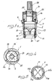
- Figure 1 is an exploded perspective view showing the shutter according to the present invention;
- Figure 2 is another perspective view showing the shutter of the invention;
- Figure 3 is an axial cross-sectional view showing the shutter according to the invention;
- Figure 4 is a cross-sectional view of the shutter, taken substantially along the line V-V of Figure 3.
- With reference to the Figures of the accompanying drawings, the preset loading ceramics disc shutter, for faucet in general, according to the invention, and which has been overally indicated at the reference number 1, comprises a
shutter body 2, which can be introduced in a faucet, not shown in the drawings. - More specifically, the
shutter body 2 has a substantially cylindrical shape and is provided, at an intermediate portion thereof, with anouter thread 5, thereabove apolygonal body 6 is provided for affixing it inside the body of a faucet. - Under the
polygonal region 6, which practically acts as an abutment, a first 0-ring 7 is provided, for tightness purposes. - In its inside, the
shutter body 2 defines a cavity, overally indicated at thereference number 10, in the inside of which a fixedceramics disc 11 is housed, thereon acts, by contact, amovable ceramics disc 12 arranged atwindows 13 defined through thebody 2. - The
ceramics discs - Depending on the shape of the water windows, it will be possible to pass from an opening condition to a closing condition, by means of a rotation through 90 or 180°.
- More specifically, the
movable ceramics disc 12 is coupled to astem 5 and is provided with a polygonal region orportion 20, therewith awasher 21 engages, provided with a radially extendedlug 22, which can move in a cut-off 24 defined by theedge 25 arranged at the top end of thebody 2. - The cut-off
portion 24 practically provides the rotation region of the movable disc, and has an angular extension depending on the type of the used ceramics discs, that is of 90 or 180°, depending on the angle necessary for passing from a completely opened condition to a closing condition. - The
stem 15 is further provided with an attachingend piece 28, thereto a conventional operating or driving knob or handle can be coupled. - A first main feature of the present invention is that the
cavity 10, at its bottom end, is provided with anabutment edge 30, on the top face or surface thereof engages a preloadinggasket 31, which acts on the bottom surface of thefixed ceramics disc 11. - The preloading is obtained by means of a resilient washer, or split resilient ring, preferably of the Seeger
type 35, which axially clamps thestem 15 by acting above thewasher 21. - Thus, a constant resilient loading between the two ceramics discs can be obtained, which resilient loading will be independent from the force clamping the shutter body in the seat of the faucet body.
- In order to provide for the tightness between the shutter and faucet body, a
tightness gasket 40 is further provided, which engages with the bottom surface of theabutment edge 30 and which can be clamped, in any suitable ways, against the mentioned seat, in order to provide the desired tightness, whithout affecting the clamping force between the two ceramics discs. - The fixed
ceramics disc 11 is further provided with radially extending lugs, indicated at 11a, which engage withcorresponding recesses 11b defined by thecavity 10 so as prevent the fixed ceramics disc from rotating. - In this connection it should be apparant that, by simply changing the location of the
washer 21 with respect to thepolygonal portion 20, it will be possible to transform the faucet from a rightward opening type to a lefward opening type, and viceversa, thereby affording the possibility of making a very flexible faucet adapted to be fitted to very different installations, and without the need of completely disassembling the shutter body, as is necessary in known prior art solutions. - From the above disclosure, it should be pointed out that the present invention fully achieves the intended task and objects.
- In particular, the fact is to be stressed that a ceramics disc shutter has been provided which affords the possibility of always obtaining the proper resilient force between the two ceramics discs, independently from the conditions of the abutment seat defined on the body of the faucet.
- Moreover, the shutter according to the invention can be fitted to faucets of the leftward and rightward opening type, since it will be sufficient to turn through 90° or 180°, depending on the used ceramics disc type, the
washer 20. - Another main feature of the present in vention is that a ceramics disc shutter has been provided which can easily be fitted to already existing conventional faucets, without the need of carrying out any important modifications.
- The invention as disclosed is susceptible to many modifications and variations all of which will come within the spirit and scope of the invention.
- Moreover, all of the details may be replaced by other tecnically equivalent elements.
- In practicing the invention, the used materials, provided that they are compatible to the intended use, as well as the contingent size and shapes, can be any according to the needs.
Claims (5)
Applications Claiming Priority (2)
| Application Number | Priority Date | Filing Date | Title |
|---|---|---|---|
| IT20757/88A IT1217735B (en) | 1988-05-26 | 1988-05-26 | CERAMIC DISC SHUTTER WITH PERFORMANCE CHARGE FOR TAPS IN GENERAL |
| IT2075788 | 1988-05-26 |
Publications (2)
| Publication Number | Publication Date |
|---|---|
| EP0343312A2 true EP0343312A2 (en) | 1989-11-29 |
| EP0343312A3 EP0343312A3 (en) | 1990-02-07 |
Family
ID=11171620
Family Applications (1)
| Application Number | Title | Priority Date | Filing Date |
|---|---|---|---|
| EP88830318A Withdrawn EP0343312A3 (en) | 1988-05-26 | 1988-07-22 | Ceramics disc shutter for faucets |
Country Status (3)
| Country | Link |
|---|---|
| EP (1) | EP0343312A3 (en) |
| IT (1) | IT1217735B (en) |
| PT (1) | PT89926A (en) |
Cited By (6)
| Publication number | Priority date | Publication date | Assignee | Title |
|---|---|---|---|---|
| EP0441335A1 (en) * | 1990-02-09 | 1991-08-14 | ZANETTA CAV.GIOVANNI &C. S.N.C. | Valve for taps and fittings, in particular of the type with ceramic disks |
| WO1995028585A1 (en) * | 1994-04-15 | 1995-10-26 | Kohler Co. | Fluid cartridge valve |
| KR100714503B1 (en) * | 2005-11-28 | 2007-05-07 | 신한콘트롤밸브 주식회사 | Temperature control valve for hot water distributor |
| KR100714502B1 (en) * | 2005-11-28 | 2007-05-07 | 신한콘트롤밸브 주식회사 | Flow control valve for hot water distributor |
| KR100907344B1 (en) | 2007-09-19 | 2009-07-13 | 주식회사 한 에너지 시스템 | Valve structure of hot water distributor |
| EP4137722A1 (en) * | 2021-08-18 | 2023-02-22 | Flühs Drehtechnik GmbH | Valve cartridge |
Family Cites Families (4)
| Publication number | Priority date | Publication date | Assignee | Title |
|---|---|---|---|---|
| US3780758A (en) * | 1972-11-15 | 1973-12-25 | Wolverine Brass Works Ind Inc | Non-metallic cartridge valve |
| DE3045410A1 (en) * | 1980-12-02 | 1982-07-01 | Hansa Metallwerke Ag, 7000 Stuttgart | SANITARY SHUT-OFF VALVE TOP |
| DE3234643A1 (en) * | 1982-09-18 | 1984-03-22 | Ideal-Standard Gmbh, 5300 Bonn | UPPER PART CARTRIDGE FOR A SANITARY SINGLE SHUT-OFF VALVE |
| FR2554902B1 (en) * | 1983-11-10 | 1986-02-21 | Mingori Ets | IMPROVED TAP HEAD |
-
1988
- 1988-05-26 IT IT20757/88A patent/IT1217735B/en active
- 1988-07-22 EP EP88830318A patent/EP0343312A3/en not_active Withdrawn
-
1989
- 1989-03-07 PT PT89926A patent/PT89926A/en not_active Application Discontinuation
Cited By (8)
| Publication number | Priority date | Publication date | Assignee | Title |
|---|---|---|---|---|
| EP0441335A1 (en) * | 1990-02-09 | 1991-08-14 | ZANETTA CAV.GIOVANNI &C. S.N.C. | Valve for taps and fittings, in particular of the type with ceramic disks |
| WO1995028585A1 (en) * | 1994-04-15 | 1995-10-26 | Kohler Co. | Fluid cartridge valve |
| KR100714503B1 (en) * | 2005-11-28 | 2007-05-07 | 신한콘트롤밸브 주식회사 | Temperature control valve for hot water distributor |
| KR100714502B1 (en) * | 2005-11-28 | 2007-05-07 | 신한콘트롤밸브 주식회사 | Flow control valve for hot water distributor |
| KR100907344B1 (en) | 2007-09-19 | 2009-07-13 | 주식회사 한 에너지 시스템 | Valve structure of hot water distributor |
| EP4137722A1 (en) * | 2021-08-18 | 2023-02-22 | Flühs Drehtechnik GmbH | Valve cartridge |
| WO2023020913A1 (en) * | 2021-08-18 | 2023-02-23 | Flühs Drehtechnik GmbH | Valve cartridge |
| US12540677B2 (en) | 2021-08-18 | 2026-02-03 | Flühs Drehtechnik GmbH | Valve cartridge |
Also Published As
| Publication number | Publication date |
|---|---|
| IT1217735B (en) | 1990-03-30 |
| PT89926A (en) | 1989-11-30 |
| EP0343312A3 (en) | 1990-02-07 |
| IT8820757A0 (en) | 1988-05-26 |
Similar Documents
| Publication | Publication Date | Title |
|---|---|---|
| US5832952A (en) | Valve assembly with reversible stop | |
| US4821765A (en) | Valve for faucet or the like | |
| US5273255A (en) | Quarter turn tap | |
| US3854493A (en) | Valve cartridge | |
| US5010917A (en) | Fluid control valve | |
| EP0373123A2 (en) | Pair of cooperating disks to control the delivery of liquid in so-called "screw" valves | |
| JP4168181B2 (en) | Spherical segment control type flat plate mixing valve | |
| EP0343312A2 (en) | Ceramics disc shutter for faucets | |
| KR20180005788A (en) | Valve | |
| US11828416B2 (en) | Gas cylinder valve with radially extending operating handle | |
| EP1230501B1 (en) | Valve sealing means | |
| US4651774A (en) | Single-lever mixer | |
| US4004775A (en) | Plug valve | |
| EP0552136A1 (en) | Improved butterfly valve | |
| EP0441335A1 (en) | Valve for taps and fittings, in particular of the type with ceramic disks | |
| US5467965A (en) | Valve system | |
| EP0551059B1 (en) | Cartridge for ceramic discs for mixing cocks | |
| EP0461294B1 (en) | Stop valve | |
| CN220910480U (en) | Multifunctional flow regulating valve | |
| US6164330A (en) | Valve having a flow blocking rotary body | |
| RU2011911C1 (en) | Cock | |
| CN114321421B (en) | a valve | |
| US6073910A (en) | Coupling for connecting two pipe parts | |
| WO1993007408A1 (en) | Butterfly valve with compound movement | |
| KR200264338Y1 (en) | slide type gate valve for pipe |
Legal Events
| Date | Code | Title | Description |
|---|---|---|---|
| PUAI | Public reference made under article 153(3) epc to a published international application that has entered the european phase |
Free format text: ORIGINAL CODE: 0009012 |
|
| AK | Designated contracting states |
Kind code of ref document: A2 Designated state(s): BE CH DE ES FR GB GR LI NL |
|
| PUAL | Search report despatched |
Free format text: ORIGINAL CODE: 0009013 |
|
| AK | Designated contracting states |
Kind code of ref document: A3 Designated state(s): BE CH DE ES FR GB GR LI NL |
|
| 17P | Request for examination filed |
Effective date: 19900615 |
|
| 17Q | First examination report despatched |
Effective date: 19911008 |
|
| STAA | Information on the status of an ep patent application or granted ep patent |
Free format text: STATUS: THE APPLICATION IS DEEMED TO BE WITHDRAWN |
|
| 18D | Application deemed to be withdrawn |
Effective date: 19920219 |