EP0343084A1 - Verfahren und Schelle zum Befestigen einer steifen Leitung - Google Patents
Verfahren und Schelle zum Befestigen einer steifen Leitung Download PDFInfo
- Publication number
- EP0343084A1 EP0343084A1 EP89401387A EP89401387A EP0343084A1 EP 0343084 A1 EP0343084 A1 EP 0343084A1 EP 89401387 A EP89401387 A EP 89401387A EP 89401387 A EP89401387 A EP 89401387A EP 0343084 A1 EP0343084 A1 EP 0343084A1
- Authority
- EP
- European Patent Office
- Prior art keywords
- collar
- collars
- piping
- profile
- perimeter
- Prior art date
- Legal status (The legal status is an assumption and is not a legal conclusion. Google has not performed a legal analysis and makes no representation as to the accuracy of the status listed.)
- Ceased
Links
- 238000000034 method Methods 0.000 title claims description 15
- 239000002184 metal Substances 0.000 claims description 3
- 229910001220 stainless steel Inorganic materials 0.000 claims description 2
- 239000010935 stainless steel Substances 0.000 claims description 2
- 239000002537 cosmetic Substances 0.000 description 2
- 238000012423 maintenance Methods 0.000 description 2
- 230000002411 adverse Effects 0.000 description 1
- 238000004140 cleaning Methods 0.000 description 1
- 230000000295 complement effect Effects 0.000 description 1
- -1 drinks Substances 0.000 description 1
- 239000012530 fluid Substances 0.000 description 1
- 235000013305 food Nutrition 0.000 description 1
- 239000007788 liquid Substances 0.000 description 1
- 239000008267 milk Substances 0.000 description 1
- 210000004080 milk Anatomy 0.000 description 1
- 235000013336 milk Nutrition 0.000 description 1
- 230000000284 resting effect Effects 0.000 description 1
- 239000000126 substance Substances 0.000 description 1
Images

Classifications
-
- F—MECHANICAL ENGINEERING; LIGHTING; HEATING; WEAPONS; BLASTING
- F16—ENGINEERING ELEMENTS AND UNITS; GENERAL MEASURES FOR PRODUCING AND MAINTAINING EFFECTIVE FUNCTIONING OF MACHINES OR INSTALLATIONS; THERMAL INSULATION IN GENERAL
- F16L—PIPES; JOINTS OR FITTINGS FOR PIPES; SUPPORTS FOR PIPES, CABLES OR PROTECTIVE TUBING; MEANS FOR THERMAL INSULATION IN GENERAL
- F16L3/00—Supports for pipes, cables or protective tubing, e.g. hangers, holders, clamps, cleats, clips, brackets
- F16L3/16—Supports for pipes, cables or protective tubing, e.g. hangers, holders, clamps, cleats, clips, brackets with special provision allowing movement of the pipe
- F16L3/18—Supports for pipes, cables or protective tubing, e.g. hangers, holders, clamps, cleats, clips, brackets with special provision allowing movement of the pipe allowing movement in axial direction
Definitions
- the invention relates to a method for holding a rigid pipe, and a collar for implementing this method.
- Collars surrounding the profile of the piping and fixed on a support, for example a wall, are commonly used for the maintenance of rigid pipes.
- Each collar comprises two half-collars articulated to each other at a location on the perimeter of the collar, and having at the opposite location with respect to the axis of the piping clamping means making it possible to bring the two half-pieces together. clamps to each other and tighten them on the piping.
- These collars are used in particular in the food-processing, cosmetic and parapharmaceutical industries, in connection with pipes carrying bacteriologically sensitive liquids such as milk, drinks, cosmetic products, etc. They allow in particular the dismantling of pipes with a view to cleaning them up or extending the networks.
- the clamping means comprise a rod threaded attached to one of the half-collars and a nut resting on a flange belonging to the other half-collar.
- Swiss Patent 562,980 provides each of the metal half-collars with a plastic band covering the face of the latter facing the piping. These plastic bands extend between clamps provided in two diametrically opposite locations of the collar. The two half-collars are tightened one on the other by their flanges, via the plastic bands, and not on the piping.
- the plastic strips can age due to the high temperature of the piping and / or substances present in the workshop atmosphere. In addition, they risk being deformed or displaced by movements of the piping.
- the object of the invention is to eliminate these drawbacks.
- the invention relates to a method of holding rigid piping by means of collars surrounding the profile of the piping and fixed on a support, each collar comprising two half-collars which can be brought together by means tightening provided in at least one place of the perimeter of the collar, process in which the tightening means are tightened until bringing the two half-collars in mutual support in said place (s) without tighten the half-collars on the piping so as to allow it to slide longitudinally relative to the collars.
- the collars have a substantially polygonal profile, so as to come into contact with the piping at discrete locations around its perimeter.
- each collar comprises clamping means in a first location and an articulation between the two half-collars at the location of its perimeter opposite the first relative to the axis of the piping.
- each collar has clamping means in two places of its perimeter, opposite to each other relative to the axis of the piping.
- the invention also relates to a collar for holding a pipe by the method defined above, comprising two half-collars which can be brought into mutual support, at least in one place of the perimeter of the collar, by means tightening, by forming a rigid ring with a substantially polygonal profile circumscribing the profile of the piping for which the collar is intended without being tightened thereon.
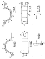
- the collar 1 illustrated in FIG. 1 comprises two identical half-collars 2 and 3, each formed from a strip of stainless steel with a width of approximately 25 mm and a thickness of approximately 2.5 mm.
- the strip is folded in transverse folds to form three adjacent faces 4,5 and 6 of a prism with regular hexagonal section, as well as two end flanges 7 and 8 extending in the same plane towards the outside of the prism .
- Forming the collar 1 by placing the two half-collars 2 and 3 so that the flanges 7 and 8 are two by two opposite one another and that the segments 4, 5 and 6 together constitute a regular hexagonal prism.
- Two screws 9 are engaged in holes 10 provided in the flanges 7 and 8 and nuts 11 are screwed onto these screws until the flanges are tightened between the nuts and the heads 12 of the screws.
- the collar 21 comprises an upper half-collar 22 and a lower half-collar 23 cut in a strip similar to that from which the half-collars 2 and 3 described above are produced.
- the half-collar 22 comprises three segments 24, 25 and 26 whose shape and relative arrangement are similar to those of the segments 4, 5 and 6 of the half-collar 2.
- To the segment 26 is connected a terminal flange 28 similar to the flange 8, except that the hole 10 is replaced therein by a longitudinal notch 30 extending from the free end of the flange.
- the flange 7 of the half-collar 2 is replaced in the half-collar 22 by a portion 27 rolled in the form of a hinge towards the outside of the collar and which extends only over a median part of the width of the strip.
- the lower half-collar 23 also comprises segments 24 ′, 25 ′ and 26 ′ similar to segments 4, 5 and 6 of the half-collar 3 and arranged in the same way with respect to each other.
- a 28 ′ terminal flange dant segment 26 ′ first extends from there in the same direction as the flange 8 of the half-collar 3, then wraps in the form of a hinge on the opposite side with respect to the flange 28 of the half-collar 22.
- the hinge 43 thus formed extends only over two marginal portions of the width of the strip constituting the half-collar 23.
- the half-collar 23 has, in the extension of segment 24 ′, a portion 27 ′ rolled in the shape of a hinge outside the collar and extending over two marginal parts of the width of the band complementary to the median part occupied by the hinge 27 of the half-collar 22.
- the half-collars 22 and 23 are arranged so that their segments 24, 25, 26 and 24 ′, 25 ′, 26 ′ form a regular hexagonal prism, the hinge 27 coming to align between the two parts of the hinge 27 ′, and a cylindrical rod 44 as shown in FIG. 10 is threaded into the latter, which constitutes a mutual articulation axis of the two half-collars.
- Another cylindrical rod 45 similar to the rod 44 is threaded in the two parts of the hinge 43 and in the end part 46 of a threaded rod 47 which has for this purpose a transverse hole 48.
- the end part 46 is disposed between the two parts of the hinge 43, so that the threaded rod 47 can pivot relative to the half-collar 23 around the axis formed by the rod 45. It can then penetrate into the notch 30, allowing a nut 42 cooperating with its thread to lean on the flange 28 and apply it against the flange 28 ′, as shown in Figures 3 and 4.
- FIG. 3 and 4 There is shown in Figures 3 and 4 a circle 49 which fits into the inner profile of the hexagonal collar, and which corresponds to the profile of the piping to which is intended the necklace.
- Standardized pipe diameters are used in the food industry, the most common of which are 25, 38, 51, 63.5, 76 and 104 mm.
- the collars according to the invention are therefore dimensioned so that the diameter of the circle 49 corresponds to these values.
- the collar not being tightened on the piping, the latter can slide there freely according to its expansion, without stresses occurring leading to deformations or ruptures.
- the piping due to the hexagonal profile of the collar, the piping can only come into contact with it in discrete areas of its perimeter, thus reducing friction and facilitating the sliding of the piping.
- the collar 21 is equipped with conventional fastening elements, namely respectively a tube 50 intended to be welded on a fixed support and a threaded sleeve 51 intended to be screwed on such a support.
- These elements 50 and 51 are welded on the middle segment 25 ′ of the half-collar 23. They could also be welded on another segment.
- the hexagonal profile illustrated for the collar can be replaced by another polygonal profile, or by any other profile providing discrete contact areas with the piping.
Landscapes
- Engineering & Computer Science (AREA)
- General Engineering & Computer Science (AREA)
- Mechanical Engineering (AREA)
- Supports For Pipes And Cables (AREA)
- Clamps And Clips (AREA)
Applications Claiming Priority (2)
| Application Number | Priority Date | Filing Date | Title |
|---|---|---|---|
| FR8806727A FR2631679B1 (fr) | 1988-05-19 | 1988-05-19 | Procede et collier pour le maintien d'une tuyauterie rigide |
| FR8806727 | 1988-05-19 |
Publications (1)
| Publication Number | Publication Date |
|---|---|
| EP0343084A1 true EP0343084A1 (de) | 1989-11-23 |
Family
ID=9366448
Family Applications (1)
| Application Number | Title | Priority Date | Filing Date |
|---|---|---|---|
| EP89401387A Ceased EP0343084A1 (de) | 1988-05-19 | 1989-05-19 | Verfahren und Schelle zum Befestigen einer steifen Leitung |
Country Status (2)
| Country | Link |
|---|---|
| EP (1) | EP0343084A1 (de) |
| FR (1) | FR2631679B1 (de) |
Cited By (2)
| Publication number | Priority date | Publication date | Assignee | Title |
|---|---|---|---|---|
| EP0523383A1 (de) * | 1991-07-05 | 1993-01-20 | FRATELLI TASSALINI SpA. | Rohrstuetze |
| US6450736B1 (en) * | 2001-04-27 | 2002-09-17 | Phillips Petroleum Company | Movable supports for pipelines |
Citations (4)
| Publication number | Priority date | Publication date | Assignee | Title |
|---|---|---|---|---|
| CH562980A5 (en) * | 1973-03-27 | 1975-06-13 | Gebert & Cie | Pipe clip with removable sector-type strips - these fit into semicircular halves secured between coupling flanges |
| DE2854924A1 (de) * | 1978-12-20 | 1980-06-26 | Dick Gmbh Dipa | Rohrschelle fuer kalte stoffe fuehrende rohre |
| FR2520945A1 (fr) * | 1982-01-29 | 1983-08-05 | Essilor Int | Dispositif de fixation de cable d'alimentation ou de sortie |
| FR2591709A1 (fr) * | 1985-12-13 | 1987-06-19 | Weiss Jacques | Collier support de tuyau |
-
1988
- 1988-05-19 FR FR8806727A patent/FR2631679B1/fr not_active Expired - Fee Related
-
1989
- 1989-05-19 EP EP89401387A patent/EP0343084A1/de not_active Ceased
Patent Citations (4)
| Publication number | Priority date | Publication date | Assignee | Title |
|---|---|---|---|---|
| CH562980A5 (en) * | 1973-03-27 | 1975-06-13 | Gebert & Cie | Pipe clip with removable sector-type strips - these fit into semicircular halves secured between coupling flanges |
| DE2854924A1 (de) * | 1978-12-20 | 1980-06-26 | Dick Gmbh Dipa | Rohrschelle fuer kalte stoffe fuehrende rohre |
| FR2520945A1 (fr) * | 1982-01-29 | 1983-08-05 | Essilor Int | Dispositif de fixation de cable d'alimentation ou de sortie |
| FR2591709A1 (fr) * | 1985-12-13 | 1987-06-19 | Weiss Jacques | Collier support de tuyau |
Cited By (2)
| Publication number | Priority date | Publication date | Assignee | Title |
|---|---|---|---|---|
| EP0523383A1 (de) * | 1991-07-05 | 1993-01-20 | FRATELLI TASSALINI SpA. | Rohrstuetze |
| US6450736B1 (en) * | 2001-04-27 | 2002-09-17 | Phillips Petroleum Company | Movable supports for pipelines |
Also Published As
| Publication number | Publication date |
|---|---|
| FR2631679B1 (fr) | 1990-08-31 |
| FR2631679A1 (fr) | 1989-11-24 |
Similar Documents
| Publication | Publication Date | Title |
|---|---|---|
| EP0027406B1 (de) | Mit einem Kettenring versehene Rohrverbindung | |
| FR2760510A1 (fr) | Dispositif de serrage pour tubes et son procede de realisation | |
| BE898358A (fr) | Structure de serrage sans oreille. | |
| FR2618870A1 (fr) | Collier de serrage pour le raccordement de deux tubes metalliques | |
| FR2666635A1 (fr) | Accouplement tubulaire. | |
| BE1009879A4 (fr) | Piece moulee en matiere thermoplastique. | |
| FR2550312A1 (fr) | Raccord pour tubes | |
| FR2863335A1 (fr) | Collier de serrage | |
| EP1540229B1 (de) | Klemmring | |
| EP0343084A1 (de) | Verfahren und Schelle zum Befestigen einer steifen Leitung | |
| FR2690966A3 (fr) | Outil destiné à désaérer des systèmes hydrauliques. | |
| FR2620176A1 (fr) | Collier de serrage muni d'un ruban a boucles fendues, pour la suspension d'un systeme de solidarisation par fermeture | |
| FR2576389A1 (fr) | Dispositif de jonction entre deux tuyaux comportant des pieces d'appui escamotables | |
| EP0067264B1 (de) | Undurchlässige Verbindung für verformbare Rohre | |
| EP1413815A1 (de) | Kupplung für zwei Rohre mit aufgeweiteten Enden | |
| EP1231422B1 (de) | Verfahren zur Herstellung einer unverlierbaren Schraube, Fixierungstellringe für Rohrleitungen und Gebrauch von dem Prozess, die Stellringe herzustellen | |
| EP0082792B1 (de) | Umgreifvorrichtung zum Abdichten von Lecks an einer Flanschverbindung einer Kanalisation | |
| FR2576388A1 (fr) | Dispositif pour le raccordement axial de deux tubes sans manchon | |
| EP0232671B1 (de) | Abdichtung für die Verbindung von zwei Rohrelementen mit Einsteckende und mit Muffe | |
| FR2718215A1 (fr) | Collier de serrage à effet de soulagement en traction axiale, pour relier les extrémités de deux tubes. | |
| FR2564563A1 (fr) | Dispositif pour fixer l'extremite d'un tuyau souple a un raccord | |
| EP0710794A1 (de) | Vorrichtung zum Verbinden eines Rohres an einem Rohreinsatz | |
| FR2489472A1 (fr) | Dispositif de securite pour empecher le deplacement axial de liaisons par manchon de conduits tubulaires en matiere synthetique | |
| EP0475328B1 (de) | Vorrichtung zum Einschränken von Leckagen im Falle eines Rohrbruches | |
| LU82667A1 (fr) | Raccord pour tubes a bouts lisses |
Legal Events
| Date | Code | Title | Description |
|---|---|---|---|
| PUAI | Public reference made under article 153(3) epc to a published international application that has entered the european phase |
Free format text: ORIGINAL CODE: 0009012 |
|
| AK | Designated contracting states |
Kind code of ref document: A1 Designated state(s): AT BE DE ES FR GB GR IT NL SE |
|
| 17P | Request for examination filed |
Effective date: 19900523 |
|
| 17Q | First examination report despatched |
Effective date: 19910125 |
|
| STAA | Information on the status of an ep patent application or granted ep patent |
Free format text: STATUS: THE APPLICATION HAS BEEN REFUSED |
|
| 18R | Application refused |
Effective date: 19930704 |