EP0342872A2 - A gas venting device - Google Patents
A gas venting device Download PDFInfo
- Publication number
- EP0342872A2 EP0342872A2 EP89304818A EP89304818A EP0342872A2 EP 0342872 A2 EP0342872 A2 EP 0342872A2 EP 89304818 A EP89304818 A EP 89304818A EP 89304818 A EP89304818 A EP 89304818A EP 0342872 A2 EP0342872 A2 EP 0342872A2
- Authority
- EP
- European Patent Office
- Prior art keywords
- valve
- gas
- back pressure
- escape
- mould half
- Prior art date
- Legal status (The legal status is an assumption and is not a legal conclusion. Google has not performed a legal analysis and makes no representation as to the accuracy of the status listed.)
- Withdrawn
Links
- 238000013022 venting Methods 0.000 title claims abstract description 15
- 239000002184 metal Substances 0.000 claims abstract description 5
- 238000004512 die casting Methods 0.000 claims abstract description 4
- 238000000465 moulding Methods 0.000 claims abstract description 3
- 229920003023 plastic Polymers 0.000 claims abstract description 3
- 239000004033 plastic Substances 0.000 claims abstract description 3
- 238000005266 casting Methods 0.000 claims description 2
- 239000000155 melt Substances 0.000 abstract description 4
- 238000010137 moulding (plastic) Methods 0.000 description 2
- 241000167857 Bourreria Species 0.000 description 1
- 229910000831 Steel Inorganic materials 0.000 description 1
- 230000000295 complement effect Effects 0.000 description 1
- 239000010959 steel Substances 0.000 description 1
Images


Classifications
-
- B—PERFORMING OPERATIONS; TRANSPORTING
- B22—CASTING; POWDER METALLURGY
- B22D—CASTING OF METALS; CASTING OF OTHER SUBSTANCES BY THE SAME PROCESSES OR DEVICES
- B22D17/00—Pressure die casting or injection die casting, i.e. casting in which the metal is forced into a mould under high pressure
- B22D17/20—Accessories: Details
- B22D17/22—Dies; Die plates; Die supports; Cooling equipment for dies; Accessories for loosening and ejecting castings from dies
-
- B—PERFORMING OPERATIONS; TRANSPORTING
- B22—CASTING; POWDER METALLURGY
- B22D—CASTING OF METALS; CASTING OF OTHER SUBSTANCES BY THE SAME PROCESSES OR DEVICES
- B22D17/00—Pressure die casting or injection die casting, i.e. casting in which the metal is forced into a mould under high pressure
- B22D17/14—Machines with evacuated die cavity
- B22D17/145—Venting means therefor
-
- B—PERFORMING OPERATIONS; TRANSPORTING
- B29—WORKING OF PLASTICS; WORKING OF SUBSTANCES IN A PLASTIC STATE IN GENERAL
- B29C—SHAPING OR JOINING OF PLASTICS; SHAPING OF MATERIAL IN A PLASTIC STATE, NOT OTHERWISE PROVIDED FOR; AFTER-TREATMENT OF THE SHAPED PRODUCTS, e.g. REPAIRING
- B29C33/00—Moulds or cores; Details thereof or accessories therefor
- B29C33/10—Moulds or cores; Details thereof or accessories therefor with incorporated venting means
Definitions
- the device illustrated has a gas escape valve a to vent gas from a mould.
- the valve a is constantly biased to a closed position by pneumatic pressure applied at b , and the valve is backed up by a steel ball c pressed by a spring with a stronger force than the pneumatic pressure. In this way the working position of the valve is maintained against any impact given upon the valve by such as molten metal or plastics.
- the gas escape valve of such a gas venting device can be readily openable to allow gas to pass through.
- the secondary runner 8 includes ramps 12 formed on the joint face 11 of the fixed mould half 10.
- the ramps 12 are designed to allow a melt to rise up along their raised surface.
- the fixed mould half 10 includes gas vents 13 and has a pouring hole 14 connected to the primary runner 1.
- Figure 6 shows modified back pressure escape multi-grooves 37 and projections 39 each having a saw-tooth shape.
- Figure 7 shows further modified back pressure escape multi-grooves 47 formed in square-thread patterns.
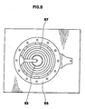
- Figure 8 shows still further modified back pressure escape ring-shaped grooves 57 formed concentric with a gas escape duct 53, the ring-shaped grooves 57 communicating between a cavity 55 and a gas escape duct 53.
- Figure 9 shows a valve rod 61 covered with a cup-shaped cover 60 so as to protect the valve 16 against becoming stained with dirt.
- Figure 10 shows a valve rod 71 carried by a bearing 72 such that the valve rod 71 is smoothly slidable therein.
Landscapes
- Engineering & Computer Science (AREA)
- Mechanical Engineering (AREA)
- Moulds For Moulding Plastics Or The Like (AREA)
- Molds, Cores, And Manufacturing Methods Thereof (AREA)
Abstract
A gas venting device, for venting high pressure gas from a metal diecasting or plastics moulding mould having a mould cavity (5), comprises a gas escape valve (16) normally held open by pneumatic pressure supplied through a duct (19) to act on a piston (18) thereby to allow gas to vent from the mould cavity (5) via a duct (6) formed by inter engaged multi grooves (7) and projections and leading, via the gas escape valve (16), to a vent (13), until a back pressure of the melt acts on the head of the valve (16) and closes the valve (16).
Description
- The invention relates to a gas venting device for use in metal diecasting and plastic moulding machines.
- To explain the background to the invention, reference will be made to Figures 11 and 12, of the accompanying drawings which show a typical example of previously proposed gas venting devices.
- The device illustrated has a gas escape valve a to vent gas from a mould. The valve a is constantly biased to a closed position by pneumatic pressure applied at b, and the valve is backed up by a steel ball c pressed by a spring with a stronger force than the pneumatic pressure. In this way the working position of the valve is maintained against any impact given upon the valve by such as molten metal or plastics.
- In the gas venting of such kind a problem is that the pressure must be constantly applied to the valve a so as to close it, and the valve is kept closed by an overwhelming force over the pressure. Under this system the gas escape valve is very likely to close if any unexpected relatively strong force acts on the valve head. If it happens, a high pressure gas is continuously confined in the cavity of the mould.
- According to the invention there is provided a gas venting device for use in metal diecasting or plastic moulding machines comprising at least one back pressure escape groove of zigzag form in the joint face of a first mould half, at least one back pressure escape projection of zigzag form on a joint face of a second mould half such that the back pressure escape groove and the back pressure escape projection inter engage to form a back pressure escape duct when the two mould halves abut together, a gas escape valve movably provided in the second mould half and connected to the back pressure escape duct, a casting cavity in the first mould half, a groove in each mould half which form a runner in the joint interface when the two mould halves are abutted, and a pressure supply duct to supply pneumatic pressure to the valve so as to keep it open by pneumatic pressure.
- The gas escape valve of such a gas venting device can be readily openable to allow gas to pass through.
- The invention is diagrammatically illustrated by way of example in the accompanying drawings, in which:-
- Figure 1 is a plan view showing a movable mould half of a moulding machine including a gas venting device according to the invention;
- Figure 2 is a perspective view of the movable mould half of Figure 1;
- Figure 3 is a perspective view showing a fixed mould half to cooperate with the mould half of Figure 1 and 2;
- Figure 4 is a cross-sectional view showing an assembly of the movable mould half and the fixed mould half taken on lines A-A in Figures 1 and 3;
- Figure 5 is a cross-sectional view taken on lines B-B in Figures 1 and 3;
- Figure 6 is a view similar to Figure 4 showing a modified version of back pressure escape grooves;
- Figures 7 and 8 are views similar to Figure 1 showing two further modified versions of back pressure escape grooves;
- Figures 9 and 10 are views similar to Figure 4 showing two different modified versions of valve sections;
- Figure 11 is a cross-sectional view through a gas venting device of previously proposed kind; and
- Figure 12 is a side view of the gas venting device of Figure 11.
- Referring to Figures 1 and 2, a gas venting device includes a primary runner 1 formed in a joint face 3 of a movable mould half 2. The runner 1 is connected to an outlet 4. A
cavity 5 in which products are cast includes a gasvent escape ducts 6.Multiple grooves 7 are provided in the face 3 to form part of the backpressure escape ducts 6. Thecavity 5 includes asecondary runner 8. Figure 3 shows afixed mould half 10 which includes backpressure escape projections 9 formed on a joint face 11 which is complementary to the joint face 3 of the movable mould half 2. Theprojections 9 are formed so as to fit into themultiple grooves 7 of the movable mould half 2 and to form therewith theescape ducts 6. Thesecondary runner 8 includesramps 12 formed on the joint face 11 of thefixed mould half 10. Theramps 12 are designed to allow a melt to rise up along their raised surface. The fixedmould half 10 includesgas vents 13 and has apouring hole 14 connected to the primary runner 1. - Referring to Figure 4, the
fixed mould half 10 includes asecond gas vent 15 connected to thefirst gas vents 13. A respectivegas escape valve 16 is slidable in each of thegas vents 13. Eachvalve 16 is supported by abearing 17, which is provided with apiston 18. Thepiston 18 can be biased to move thevalve 16 to an open position by pneumatic pressure supplied through afirst supply duct 19, whereas, if thevalve 16 is to be closed, pneumatic pressure is supplied through asecond supply duct 20.Ejector push rods 21 are slidable in the movable mould half 2. Eachvalve 16 has ahead 22. - Figure 6 shows modified back pressure escape multi-grooves 37 and
projections 39 each having a saw-tooth shape. Figure 7 shows further modified back pressure escape multi-grooves 47 formed in square-thread patterns. Figure 8 shows still further modified back pressure escape ring-shaped grooves 57 formed concentric with agas escape duct 53, the ring-shaped grooves 57 communicating between acavity 55 and agas escape duct 53. Figure 9 shows avalve rod 61 covered with a cup-shaped cover 60 so as to protect thevalve 16 against becoming stained with dirt. Figure 10 shows avalve rod 71 carried by abearing 72 such that thevalve rod 71 is smoothly slidable therein. - When the two
mould halves 2 and 10 are pressed together face to face, the back pressure escape multi-grooves 7 and theprojections 9 cooperate with each other to form thegas vents 6 having zigzag paths. Gas can pass through such zigzag paths but the melt will not be allowed to pass or will be greatly hindered because of its tenacity. As a result, pressure will build up on the cavity and urge thevalve 16 to close. Therefore, to keep thevalve 16 open a high pneumatic pressure can be applied thereto through thefirst supply duct 19 so as to overcome the closure-urging pressure which acts on the valve head. Only when a strong back pressure caused by the melt acts on the valve head will the valve be closed. Thus the valve is kept open to vent high pressure before it detrimentally builds up on the mould.
Claims (3)
1. A gas venting device for use in metal diecasting or plastics moulding machines comprising at least one back pressure escape groove (7, 37, 47, 57) of zigzag form in the joint face (3) of a first mould half (2), at least one back pressure escape projection (9, 39) of zigzag form on a joint face (11) of a second mould half (10) such that the back pressure escape groove (7, 37, 47, 57) and the back pressure escape projection (9, 39) inter engage to form a back pressure escape duct when the two mould halves (2, 10) abut together, a gas escape valve (16) movably provided in the second mould half (10) and connected to the back pressure escape duct, a casting cavity (5) in the first mould half (2), a groove in each mould half which form a runner in the joint interface (3, 11) when the two mould halves (2, 10) are abutted, and a pressure supply duct (19) to supply pneumatic pressure to the valve (16) so as to keep it open by pneumatic pressure.
2. A gas venting device according to claim 1, wherein the valve (16) is covered with a cover whereby the valve (16) is protected against dirt.
3. A gas venting device according to claim 1, wherein the valve (16) is carried by a bearing (17) whereby the valve (16) can move smoothly.
Applications Claiming Priority (2)
| Application Number | Priority Date | Filing Date | Title |
|---|---|---|---|
| JP63120139A JPH01289557A (en) | 1988-05-16 | 1988-05-16 | Air vent device for die |
| JP120139/88 | 1988-05-16 |
Publications (1)
| Publication Number | Publication Date |
|---|---|
| EP0342872A2 true EP0342872A2 (en) | 1989-11-23 |
Family
ID=14778932
Family Applications (1)
| Application Number | Title | Priority Date | Filing Date |
|---|---|---|---|
| EP89304818A Withdrawn EP0342872A2 (en) | 1988-05-16 | 1989-05-12 | A gas venting device |
Country Status (4)
| Country | Link |
|---|---|
| EP (1) | EP0342872A2 (en) |
| JP (1) | JPH01289557A (en) |
| KR (1) | KR890017024A (en) |
| BR (1) | BR8902253A (en) |
Cited By (3)
| Publication number | Priority date | Publication date | Assignee | Title |
|---|---|---|---|---|
| WO1993019920A1 (en) * | 1992-04-02 | 1993-10-14 | United Technologies Corporation | Carbon fiber reinforced polyimide composites |
| US5586596A (en) * | 1994-09-26 | 1996-12-24 | Freeman; Lewis G. | Die cast vent block |
| WO2009059650A1 (en) * | 2007-11-06 | 2009-05-14 | Electronics Gmbh Vertrieb Elektronischer Geräte | Ventilation unit for a die casting device |
Families Citing this family (2)
| Publication number | Priority date | Publication date | Assignee | Title |
|---|---|---|---|---|
| CH705077B1 (en) * | 2011-06-09 | 2016-01-29 | V D S Vacuum Diecasting Service S A | Valve device for evacuation of air from a mold. |
| KR102666180B1 (en) * | 2022-04-28 | 2024-05-16 | 캐스트테크 주식회사 | A vacuum valve block for die casting |
-
1988
- 1988-05-16 JP JP63120139A patent/JPH01289557A/en active Pending
-
1989
- 1989-05-12 EP EP89304818A patent/EP0342872A2/en not_active Withdrawn
- 1989-05-15 BR BR898902253A patent/BR8902253A/en unknown
- 1989-05-16 KR KR1019890006527A patent/KR890017024A/en not_active Withdrawn
Cited By (3)
| Publication number | Priority date | Publication date | Assignee | Title |
|---|---|---|---|---|
| WO1993019920A1 (en) * | 1992-04-02 | 1993-10-14 | United Technologies Corporation | Carbon fiber reinforced polyimide composites |
| US5586596A (en) * | 1994-09-26 | 1996-12-24 | Freeman; Lewis G. | Die cast vent block |
| WO2009059650A1 (en) * | 2007-11-06 | 2009-05-14 | Electronics Gmbh Vertrieb Elektronischer Geräte | Ventilation unit for a die casting device |
Also Published As
| Publication number | Publication date |
|---|---|
| JPH01289557A (en) | 1989-11-21 |
| BR8902253A (en) | 1990-01-09 |
| KR890017024A (en) | 1989-12-14 |
Similar Documents
| Publication | Publication Date | Title |
|---|---|---|
| EP2261000B1 (en) | Device for demoulding negatives in plastic injection moulding | |
| US5322111A (en) | Ceramic lined shot sleeve | |
| CA1257457A (en) | Mold for manufacturing flanged objects without side action | |
| CA1315059C (en) | Molding apparatus with improved ejector pin | |
| EP0342872A2 (en) | A gas venting device | |
| CA2378259C (en) | Stripper plate assembly for an injection mold with core lock wedges | |
| EP0468154B1 (en) | Improved tire mold, method and tire | |
| US4661055A (en) | Moulding assembly for the injection of plastic materials | |
| KR970061492A (en) | Method for producing a hollow molded body made of thermoplastic resin | |
| JPH01128811A (en) | Mold changeover mechanism of molding equipment | |
| US5586596A (en) | Die cast vent block | |
| CA2325405A1 (en) | Apparatus for die casting an internal passageway and a product manufactured therewith | |
| US6220848B1 (en) | Injection moulding die locking and opening device | |
| US4030869A (en) | Locating ring for injection molds | |
| JPS5871138A (en) | Mold for injection molding | |
| KR940002029A (en) | Injection Molding Apparatus and Molds for Use in Injection Molding | |
| EP0614742B1 (en) | Gas-feeding nozzle | |
| JP3114161B2 (en) | Mold equipment | |
| KR102618785B1 (en) | Container injection mold without runner | |
| JPH0515534B2 (en) | ||
| JPS6347463Y2 (en) | ||
| CA2155358A1 (en) | Injection Mould and Method for Injection Moulding an Article | |
| JPH07148792A (en) | Injection mold | |
| JPH0939039A (en) | Plastic molding die | |
| JPH04201206A (en) | mold type |
Legal Events
| Date | Code | Title | Description |
|---|---|---|---|
| PUAI | Public reference made under article 153(3) epc to a published international application that has entered the european phase |
Free format text: ORIGINAL CODE: 0009012 |
|
| AK | Designated contracting states |
Kind code of ref document: A2 Designated state(s): DE ES FR GB IT |
|
| STAA | Information on the status of an ep patent application or granted ep patent |
Free format text: STATUS: THE APPLICATION HAS BEEN WITHDRAWN |
|
| 18W | Application withdrawn |
Withdrawal date: 19900206 |
|
| R18W | Application withdrawn (corrected) |
Effective date: 19900206 |