EP0342857B1 - Waste paper de-inking system - Google Patents
Waste paper de-inking system Download PDFInfo
- Publication number
- EP0342857B1 EP0342857B1 EP19890304752 EP89304752A EP0342857B1 EP 0342857 B1 EP0342857 B1 EP 0342857B1 EP 19890304752 EP19890304752 EP 19890304752 EP 89304752 A EP89304752 A EP 89304752A EP 0342857 B1 EP0342857 B1 EP 0342857B1
- Authority
- EP
- European Patent Office
- Prior art keywords
- inking
- waste paper
- vapor
- slurry
- liquid mixer
- Prior art date
- Legal status (The legal status is an assumption and is not a legal conclusion. Google has not performed a legal analysis and makes no representation as to the accuracy of the status listed.)
- Expired - Lifetime
Links
- 239000010893 paper waste Substances 0.000 title claims description 47
- 239000002002 slurry Substances 0.000 claims description 48
- 239000007789 gas Substances 0.000 claims description 43
- 239000007788 liquid Substances 0.000 claims description 37
- 239000000203 mixture Substances 0.000 claims description 15
- 239000000835 fiber Substances 0.000 claims description 13
- 239000003795 chemical substances by application Substances 0.000 claims description 11
- 238000000034 method Methods 0.000 claims description 9
- 239000002699 waste material Substances 0.000 claims 2
- 238000010298 pulverizing process Methods 0.000 claims 1
- 230000000694 effects Effects 0.000 description 7
- 238000010586 diagram Methods 0.000 description 4
- 230000009897 systematic effect Effects 0.000 description 4
- 238000004061 bleaching Methods 0.000 description 3
- 238000011084 recovery Methods 0.000 description 3
- 238000000926 separation method Methods 0.000 description 3
- 229920001131 Pulp (paper) Polymers 0.000 description 2
- 239000000853 adhesive Substances 0.000 description 2
- 230000001070 adhesive effect Effects 0.000 description 2
- 238000006477 desulfuration reaction Methods 0.000 description 2
- 230000023556 desulfurization Effects 0.000 description 2
- 230000003009 desulfurizing effect Effects 0.000 description 2
- 239000006260 foam Substances 0.000 description 2
- 239000011148 porous material Substances 0.000 description 2
- 238000000746 purification Methods 0.000 description 2
- 239000003513 alkali Substances 0.000 description 1
- 230000001276 controlling effect Effects 0.000 description 1
- 230000003247 decreasing effect Effects 0.000 description 1
- 238000001035 drying Methods 0.000 description 1
- 230000005611 electricity Effects 0.000 description 1
- 238000005265 energy consumption Methods 0.000 description 1
- 238000004299 exfoliation Methods 0.000 description 1
- 238000005187 foaming Methods 0.000 description 1
- 239000000976 ink Substances 0.000 description 1
- 239000002650 laminated plastic Substances 0.000 description 1
- 230000003472 neutralizing effect Effects 0.000 description 1
- 230000003134 recirculating effect Effects 0.000 description 1
- 230000001105 regulatory effect Effects 0.000 description 1
- 230000000630 rising effect Effects 0.000 description 1
- 238000005201 scrubbing Methods 0.000 description 1
- 229920003002 synthetic resin Polymers 0.000 description 1
- 239000000057 synthetic resin Substances 0.000 description 1
- 239000002912 waste gas Substances 0.000 description 1
Images

Classifications
-
- D—TEXTILES; PAPER
- D21—PAPER-MAKING; PRODUCTION OF CELLULOSE
- D21C—PRODUCTION OF CELLULOSE BY REMOVING NON-CELLULOSE SUBSTANCES FROM CELLULOSE-CONTAINING MATERIALS; REGENERATION OF PULPING LIQUORS; APPARATUS THEREFOR
- D21C5/00—Other processes for obtaining cellulose, e.g. cooking cotton linters ; Processes characterised by the choice of cellulose-containing starting materials
- D21C5/02—Working-up waste paper
- D21C5/025—De-inking
-
- B—PERFORMING OPERATIONS; TRANSPORTING
- B03—SEPARATION OF SOLID MATERIALS USING LIQUIDS OR USING PNEUMATIC TABLES OR JIGS; MAGNETIC OR ELECTROSTATIC SEPARATION OF SOLID MATERIALS FROM SOLID MATERIALS OR FLUIDS; SEPARATION BY HIGH-VOLTAGE ELECTRIC FIELDS
- B03D—FLOTATION; DIFFERENTIAL SEDIMENTATION
- B03D1/00—Flotation
- B03D1/08—Subsequent treatment of concentrated product
- B03D1/082—Subsequent treatment of concentrated product of the froth product, e.g. washing
-
- B—PERFORMING OPERATIONS; TRANSPORTING
- B03—SEPARATION OF SOLID MATERIALS USING LIQUIDS OR USING PNEUMATIC TABLES OR JIGS; MAGNETIC OR ELECTROSTATIC SEPARATION OF SOLID MATERIALS FROM SOLID MATERIALS OR FLUIDS; SEPARATION BY HIGH-VOLTAGE ELECTRIC FIELDS
- B03D—FLOTATION; DIFFERENTIAL SEDIMENTATION
- B03D1/00—Flotation
- B03D1/14—Flotation machines
- B03D1/1406—Flotation machines with special arrangement of a plurality of flotation cells, e.g. positioning a flotation cell inside another
-
- B—PERFORMING OPERATIONS; TRANSPORTING
- B03—SEPARATION OF SOLID MATERIALS USING LIQUIDS OR USING PNEUMATIC TABLES OR JIGS; MAGNETIC OR ELECTROSTATIC SEPARATION OF SOLID MATERIALS FROM SOLID MATERIALS OR FLUIDS; SEPARATION BY HIGH-VOLTAGE ELECTRIC FIELDS
- B03D—FLOTATION; DIFFERENTIAL SEDIMENTATION
- B03D1/00—Flotation
- B03D1/14—Flotation machines
- B03D1/1443—Feed or discharge mechanisms for flotation tanks
- B03D1/1456—Feed mechanisms for the slurry
-
- B—PERFORMING OPERATIONS; TRANSPORTING
- B03—SEPARATION OF SOLID MATERIALS USING LIQUIDS OR USING PNEUMATIC TABLES OR JIGS; MAGNETIC OR ELECTROSTATIC SEPARATION OF SOLID MATERIALS FROM SOLID MATERIALS OR FLUIDS; SEPARATION BY HIGH-VOLTAGE ELECTRIC FIELDS
- B03D—FLOTATION; DIFFERENTIAL SEDIMENTATION
- B03D1/00—Flotation
- B03D1/14—Flotation machines
- B03D1/1443—Feed or discharge mechanisms for flotation tanks
- B03D1/1475—Flotation tanks having means for discharging the pulp, e.g. as a bleed stream
-
- D—TEXTILES; PAPER
- D21—PAPER-MAKING; PRODUCTION OF CELLULOSE
- D21C—PRODUCTION OF CELLULOSE BY REMOVING NON-CELLULOSE SUBSTANCES FROM CELLULOSE-CONTAINING MATERIALS; REGENERATION OF PULPING LIQUORS; APPARATUS THEREFOR
- D21C11/00—Regeneration of pulp liquors or effluent waste waters
- D21C11/06—Treatment of pulp gases; Recovery of the heat content of the gases; Treatment of gases arising from various sources in pulp and paper mills; Regeneration of gaseous SO2, e.g. arising from liquors containing sulfur compounds
-
- Y—GENERAL TAGGING OF NEW TECHNOLOGICAL DEVELOPMENTS; GENERAL TAGGING OF CROSS-SECTIONAL TECHNOLOGIES SPANNING OVER SEVERAL SECTIONS OF THE IPC; TECHNICAL SUBJECTS COVERED BY FORMER USPC CROSS-REFERENCE ART COLLECTIONS [XRACs] AND DIGESTS
- Y02—TECHNOLOGIES OR APPLICATIONS FOR MITIGATION OR ADAPTATION AGAINST CLIMATE CHANGE
- Y02P—CLIMATE CHANGE MITIGATION TECHNOLOGIES IN THE PRODUCTION OR PROCESSING OF GOODS
- Y02P70/00—Climate change mitigation technologies in the production process for final industrial or consumer products
- Y02P70/10—Greenhouse gas [GHG] capture, material saving, heat recovery or other energy efficient measures, e.g. motor control, characterised by manufacturing processes, e.g. for rolling metal or metal working
-
- Y—GENERAL TAGGING OF NEW TECHNOLOGICAL DEVELOPMENTS; GENERAL TAGGING OF CROSS-SECTIONAL TECHNOLOGIES SPANNING OVER SEVERAL SECTIONS OF THE IPC; TECHNICAL SUBJECTS COVERED BY FORMER USPC CROSS-REFERENCE ART COLLECTIONS [XRACs] AND DIGESTS
- Y02—TECHNOLOGIES OR APPLICATIONS FOR MITIGATION OR ADAPTATION AGAINST CLIMATE CHANGE
- Y02W—CLIMATE CHANGE MITIGATION TECHNOLOGIES RELATED TO WASTEWATER TREATMENT OR WASTE MANAGEMENT
- Y02W30/00—Technologies for solid waste management
- Y02W30/50—Reuse, recycling or recovery technologies
- Y02W30/64—Paper recycling
Definitions
- This invention relates to apparatus and a process for producing de-inked pulp from recovered waste paper which is useful for natural resources saving and energy saving in a papermaking industry.
- a high tower multi-stage vapor-liquid mixer 3 having porous plates 2, 2 in multiple stages (five stages in the embodiment shown) is provided in a high tower housing 1.
- Waste paper dissolving slurry 5 is supplied by a waste paper dissolving slurry pit 4 from above the vapor-liquid mixer 3, and treating gas 7 is supplied by a de-inking gas fan 6 from below the vapor-liquid mixer 3.
- the waste paper dissolving slurry 5 is sequentially dropped from the pores 8, 8 of the porous plates 2, 2 of the respective stages to their lower porous plates 2, and eventually stored in the bottom 9 of the housing 1.
- the treating gas 7 is successively raised from the pores 8, 8 of the porous plates 2 of the lowermost stage to the porous plates 2 of the upper stages, and eventually exhausted from an exhaust port 10 opened at the top of the high tower housing 1.
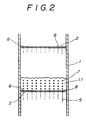
- the agitated mixture layers 11,11 composed of the waste paper dissolving slurry 5 and the treating gas 7 are respectively formed on the porous plates 2, 2 of the respective stages.
- the treating gas 7 is adsorbed and contained in the waste paper dissolving slurry 5, and the treated slurry 12 gathered in the bottom 9 of the housing is fed to next de-inking step 14 including a floatator 13.
- Fig. 1 shows the waste paper de-inking system having a centrifugal separator 15 provided before the floatator 13 in the de-inking step 14, and a slurry commutator 16 and an exhaust gas commutator 17 provided at the upper part of the high tower housing 1.
- the waste paper dissolving slurry 5 is supplied from the pit 4 through a pit pump 18 and a slurry supply port 19 to the vapor-liquid mixer 3, the treated slurry 12 in the bottom 9 of the housing 1 is fed through a housing bottom pump 20 to next de-inking step 14, and piped to the slurry supply port 19 to be able to be recirculated.
- the level of the treated slurry 12 in the bottom 9 of the housing 1 can be controlled by a LIC.
- a vapor-liquid mixture 3 is substantially the same as that of the first embodiment.
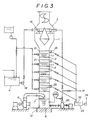
- treating gas 7 is absorbed and contained in waste paper dissolving slurry 5 in an agitated mixture layer 11 on respective porous plates 2, and a foamed floating matter layer 21 is formed on the respective agitated mixture layer 11.
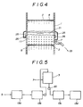
- Foamed floating matter(froth) 22 in the foamed floating matter layer 21 is discharged separately from the treated slurry 12 gathered in the bottom 9 of the housing 1 to a froth pit 23 from a froth outlet 25 as shown in Fig. 4, and fed to a froth treating step 24 to be treated.
- Adhered matters made of ink, adhesive, synthetic resin and the like adhered to the fiber and foreign matters in the waste paper dissolving slurry 5 are mainly gathered in the froth 22.
- the froth 22 can be easily discharged by raising the pressure in the high tower housing 1 slightly higher than the atmosphere by controlling the supplying amount of the treating gas 7 and the exhausting amount of the exhaust gas commutator 17.
- the vapor-liquid mixer 3 may be utilized also as a floatator.
- a plurality of froth outlets 25 are opened at the periphery of the high tower housing 1, and the opening of the outlets, the exhausting amount and the level of the agitated mixture layer 11 are regulated by a regulator 26.
- ink adhered to fiber in the waste paper dissolving slurry 5 light matters such as laminated plastic, sticky matters such as adhesives and the like, and foreign matters are separated, exfoliated, finely pulverized, and precipitated on the foam face of the foaming treating gas 7 rising from below, or floated together with foams to from a foamed floating matter layer 21. Accordingly, as the foamed floating matter layer 21 is extracted from the froth outlet 25, the foreign matters in the waste paper dissolving slurry 5 are gradually removed from the upper stage to the lower stage, and gathered in the bottom 9 of the housing 1.
- the treated slurry 12 in the bottom 9 of the housing 1 is again recirculated, as required, by a housing bottom pump 20 from the slurry supply port 19 to the vapor-liquid mixer 3 to be further purified.
- the treated slurry 12 which is not recirculated is fed to next de-inking step 14.
- the vapor-liquid mixer designated in the first embodiment can be connected in series with that shown in the second embodiment for use. Further, the vapor-liquid mixers shown in the second embodiment are used in series, vapor-liquid mixer of secondary side can be used to purify the treated slurry 12 from the vapor-liquid mixer of primary side, and from the vapor-liquid mixer of primary side, and can also be utilized as a froth treating and recovering unit for separating the fiber and foreign matters from the froth 22 derived from the primary vapor-liquid mixer.
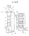
- a waste paper de-inking system for further accelerating the waste paper de-inking effect by inserting the vapor-liquid mixer 3 similar to that of the first or second embodiment into the intermediate between the intermediate floatator 13b of a plurality of floatators 13 (four stages of 13a, 13b, 13c, 13d in the exemplified example as shown) and the floatator 13c, and feeding the treated slurry from the vapor-liquid mixer 3 to the floatators 13c, 13d of the rear stages.
- de-inking agent is added into waste paper dissolving slurry as shown in Fig. 1 and 3.
- de-inking agent 28 is added from a de-inking agent tank 27 to waste paper dissolving slurry 5 in waste paper dissolving slurry pit 4.
- the agent 28 may be added to the inlet of the pit pump 18.
- the addition of the de-inking agent 28 to the waste paper dissolving slurry 5 may be performed to the agitated mixture layers 11 on the respective porous plates 2 at the intermediate of the vapor-liquid mixer 3.
- Alkali may be employed as a de-inking agent. Further, de-inking agent to be added t the front and rear stages of agitated mixture layers 11, 11 formed in multiple stages may be different in types to further accelerate the de-inking operation.
- treating gases supplied to a vapor-liquid mixer are different in types between the front stages and the rear stage.
- a single vapor-liquid mixer is employed, and as treating gas 7 initially air itself which does not substantially contain SO2 or exhaust gas produced in a factory, such as scrubber exhaust gas containing less SO2 content are used, and in case of recirculating the waste paper dissolving slurry, boiler exhaust gas containing more SO2 content is employed.
- gas containing substantially no SO2 is used as treating gas of primary vapor-liquid mixer of the front stage, and gas containing more SO2 content may be used as treating gas of the secondary vapor-liquid mixer of the rear stage.
- a waste paper de-inking system which can, in addition to the increase in the treating effect of adhered matter from the fiber and foreign matters in waste paper dissolving slurry during vapor-liquid mixing process of the front and rear stages, synergistically perform neutralizing effect of alkaline de-inking agent added slurry with SO2 and slurry bleaching effect in the rear stage.
- Exhaust gas containing the SO2 is used as treating gas to operate desulfurizing operation in the waste paper de-inking system, and to economically perform desulfurizing from various exhaust gases and environment purifying in a papermaking pulp factory.
- exhaust gases from a high temperature drying machine, a scrubber, and a boiler, etc., generated in a factory are employed as treating gas to be supplied to the vapor-liquid mixer to improve heat recovery and de-inking effect, to perform the environment purification in and out of the factory, and to improve the thermal efficiency in the entire factory.
- Fig. 6 shows still another embodiment in which multi-stage floatators 29 are provided corresponding to high tower multi-stage vapor-liquid mixer 3.
- This waste paper de-inking system has a constitution that treated slurry 13 is sequentially fed to unit floatators 30 of lower stages from unit floatator 30 of uppermost stage while removing froth 22 by the respective unit floatators 30.
- an installing area can be reduced, and power consumption can be also decreased.
- the waste paper dissolving slurry and the treating gas are agitated and mixed by the vapor-liquid mixers of multiple stage type before floatator treating step, the ink and sticky matters adhered to the fiber in the waste paper dissolving slurry are separated, finely pulverized, and the treating gas is sufficiently absorbed and contained in the slurry, thereby facilitating the de-inking in the later floatator step.
- this invention facilitates the operations, such as the separation of the adhered matters from the fiber based on the scrubbing effect of the treating gas by the fluidized layer type vapor-liquid mixer, can utilize the high tower multi-stage type vapor-liquid mixer also as the floatator to reduce the required floor area and required power consumption of the waste paper de-inking system.
- this invention provides large de-inking effect, utilizes exhaust gas containing SO2 and high temperature exhaust gas produced in a factory as treating gas to provide a waste paper de-inking system which can economically perform various operations, such as desulfurization, heat recovery and bleaching, and also purification of a factory environment.
Landscapes
- Life Sciences & Earth Sciences (AREA)
- Engineering & Computer Science (AREA)
- Biotechnology (AREA)
- Chemical & Material Sciences (AREA)
- Dispersion Chemistry (AREA)
- Treating Waste Gases (AREA)
- Paper (AREA)
Description
- This invention relates to apparatus and a process for producing de-inked pulp from recovered waste paper which is useful for natural resources saving and energy saving in a papermaking industry.
- Recently, particularly during the last twenty years, the development of a waste paper de-inking facility has been adopted as an important theme, as disclosed, for example, in JP-B-8557903 and JP-B-868196, and a number of floatators have been developed as an important component of the de-inking facility.
- In order to raise the de-inking effect of waste paper and to improve the whiteness of obtained waste paper pulp, problems arise in the conventional de-inking facilities. Thus, as the facilities are successively multiplexed, there is an increase in the required floor area upon increasing of its scale, enhanced cost as a whole, an increase in energy consumption of electricity and heat sources, and thus increased operating expenditure.
- Accordingly, it is an aim of this invention to provide a more economical waste paper de-inking system which facilitates operations, such as separation of adhered matters from fiber with a multi-stage vapor-liquid mixer, which can reduce required floor area and required power consumption of an entire facility, and which also performs operations, such as desulfurization, heat recovery and bleaching by utilizing high temperature waste gas containing SO₂ produced in a factory as treating gas to purify a factory environment.
- The invention achieves this aim by means of a waste paper de-inking apparatus having the features of claim 1 and by means of a process which comprises the steps of
claim 3. Preferred features are set forth in the subsidiary claims. - Examples of apparatus in accordance with the invention are shown in the accompanying drawings, in which :
- Fig. 1 is a systematic diagram of an arrangement including a schematic sectional view of a first embodiment of a waste paper de-inking system according to the present invention;
- Fig. 2 is an enlarged sectional view of an agitated mixture layer of Fig.1;
- Fig. 3 is a systematic diagram of an arrangement including a schematic sectional view of a second embodiment of the invention;
- Fig. 4 is an enlarged sectional view of an agitated mixture layer of Fig.3;
- Fig. 5 is a systematic diagram of an arrangement of a third embodiment of the invention; and
- Fig. 6 is a systematic diagram of an arrangement including multi-stage floatators.
- In a first embodiment of the invention shown in Fig. 1, a high tower multi-stage vapor-
liquid mixer 3 havingporous plates paper dissolving slurry 5 is supplied by a waste paper dissolvingslurry pit 4 from above the vapor-liquid mixer 3, and treatinggas 7 is supplied by ade-inking gas fan 6 from below the vapor-liquid mixer 3. The wastepaper dissolving slurry 5 is sequentially dropped from thepores porous plates porous plates 2, and eventually stored in thebottom 9 of the housing 1. The treatinggas 7 is successively raised from thepores porous plates 2 of the lowermost stage to theporous plates 2 of the upper stages, and eventually exhausted from anexhaust port 10 opened at the top of the high tower housing 1. As shown in Fig. 2, theagitated mixture layers paper dissolving slurry 5 and the treatinggas 7 are respectively formed on theporous plates agitated mixture layer 11, adhered matters adhered to the fiber in the wastepaper dissolving slurry 5 and foreign matters are separated and finely pulverized, the treatinggas 7 is adsorbed and contained in the wastepaper dissolving slurry 5, and the treatedslurry 12 gathered in thebottom 9 of the housing is fed to next de-inkingstep 14 including afloatator 13. - Fig. 1 shows the waste paper de-inking system having a
centrifugal separator 15 provided before thefloatator 13 in thede-inking step 14, and aslurry commutator 16 and anexhaust gas commutator 17 provided at the upper part of the high tower housing 1. The wastepaper dissolving slurry 5 is supplied from thepit 4 through apit pump 18 and aslurry supply port 19 to the vapor-liquid mixer 3, the treatedslurry 12 in thebottom 9 of the housing 1 is fed through ahousing bottom pump 20 to next de-inkingstep 14, and piped to theslurry supply port 19 to be able to be recirculated. The level of the treatedslurry 12 in thebottom 9 of the housing 1 can be controlled by a LIC. - In a second embodiment of the invention shown in Fig. 3, the constitution of a vapor-
liquid mixture 3 is substantially the same as that of the first embodiment. In this second embodiment, treatinggas 7 is absorbed and contained in wastepaper dissolving slurry 5 in anagitated mixture layer 11 on respectiveporous plates 2, and a foamedfloating matter layer 21 is formed on the respectiveagitated mixture layer 11. Foamed floating matter(froth) 22 in the foamedfloating matter layer 21 is discharged separately from the treatedslurry 12 gathered in thebottom 9 of the housing 1 to afroth pit 23 from afroth outlet 25 as shown in Fig. 4, and fed to afroth treating step 24 to be treated. - Adhered matters made of ink, adhesive, synthetic resin and the like adhered to the fiber and foreign matters in the waste
paper dissolving slurry 5 are mainly gathered in thefroth 22. Thefroth 22 can be easily discharged by raising the pressure in the high tower housing 1 slightly higher than the atmosphere by controlling the supplying amount of the treatinggas 7 and the exhausting amount of theexhaust gas commutator 17. - In this embodiment, the vapor-
liquid mixer 3 may be utilized also as a floatator. - In the embodiment shown in Fig. 4, a plurality of
froth outlets 25 are opened at the periphery of the high tower housing 1, and the opening of the outlets, the exhausting amount and the level of theagitated mixture layer 11 are regulated by aregulator 26. - In the second embodiment as described above, in the
agitated mixture layer 11, ink adhered to fiber in the wastepaper dissolving slurry 5, light matters such as laminated plastic, sticky matters such as adhesives and the like, and foreign matters are separated, exfoliated, finely pulverized, and precipitated on the foam face of the foaming treatinggas 7 rising from below, or floated together with foams to from a foamedfloating matter layer 21. Accordingly, as the foamedfloating matter layer 21 is extracted from thefroth outlet 25, the foreign matters in the wastepaper dissolving slurry 5 are gradually removed from the upper stage to the lower stage, and gathered in thebottom 9 of the housing 1. - The treated
slurry 12 in thebottom 9 of the housing 1 is again recirculated, as required, by ahousing bottom pump 20 from theslurry supply port 19 to the vapor-liquid mixer 3 to be further purified. The treatedslurry 12 which is not recirculated is fed to next de-inkingstep 14. - The vapor-liquid mixer designated in the first embodiment can be connected in series with that shown in the second embodiment for use. Further, the vapor-liquid mixers shown in the second embodiment are used in series, vapor-liquid mixer of secondary side can be used to purify the treated
slurry 12 from the vapor-liquid mixer of primary side, and from the vapor-liquid mixer of primary side, and can also be utilized as a froth treating and recovering unit for separating the fiber and foreign matters from thefroth 22 derived from the primary vapor-liquid mixer. - In a third embodiment shown in Fig. 5, there is shown a waste paper de-inking system for further accelerating the waste paper de-inking effect by inserting the vapor-
liquid mixer 3 similar to that of the first or second embodiment into the intermediate between theintermediate floatator 13b of a plurality of floatators 13 (four stages of 13a, 13b, 13c, 13d in the exemplified example as shown) and thefloatator 13c, and feeding the treated slurry from the vapor-liquid mixer 3 to thefloatators - In a fourth embodiment, de-inking agent is added into waste paper dissolving slurry as shown in Fig. 1 and 3. In other words, de-inking
agent 28 is added from a de-inking agent tank 27 to wastepaper dissolving slurry 5 in waste paper dissolvingslurry pit 4. Theagent 28 may be added to the inlet of thepit pump 18. When the wastepaper dissolving slurry 5 added with thede-inking agent 28 is supplied to the vapor-liquid mixer 3, the de-inking operation of the separation, exfoliation of adhered matters and foreign matters from the fiber of the wastepaper dissolving slurry 5 is further accelerated. - The addition of the
de-inking agent 28 to the wastepaper dissolving slurry 5 may be performed to theagitated mixture layers 11 on the respectiveporous plates 2 at the intermediate of the vapor-liquid mixer 3. - Alkali may be employed as a de-inking agent. Further, de-inking agent to be added t the front and rear stages of
agitated mixture layers - As a fifth embodiment, treating gases supplied to a vapor-liquid mixer are different in types between the front stages and the rear stage. In the waste paper de-inking system of this type, a single vapor-liquid mixer is employed, and as treating
gas 7 initially air itself which does not substantially contain SO₂ or exhaust gas produced in a factory, such as scrubber exhaust gas containing less SO₂ content are used, and in case of recirculating the waste paper dissolving slurry, boiler exhaust gas containing more SO₂ content is employed. - Further, two vapor-liquid mixers are employed in series, gas containing substantially no SO₂ is used as treating gas of primary vapor-liquid mixer of the front stage, and gas containing more SO₂ content may be used as treating gas of the secondary vapor-liquid mixer of the rear stage.
- In this manner, there is provided a waste paper de-inking system which can, in addition to the increase in the treating effect of adhered matter from the fiber and foreign matters in waste paper dissolving slurry during vapor-liquid mixing process of the front and rear stages, synergistically perform neutralizing effect of alkaline de-inking agent added slurry with SO₂ and slurry bleaching effect in the rear stage.
- Exhaust gas containing the SO₂ is used as treating gas to operate desulfurizing operation in the waste paper de-inking system, and to economically perform desulfurizing from various exhaust gases and environment purifying in a papermaking pulp factory.
- Particularly, exhaust gases from a high temperature drying machine, a scrubber, and a boiler, etc., generated in a factory are employed as treating gas to be supplied to the vapor-liquid mixer to improve heat recovery and de-inking effect, to perform the environment purification in and out of the factory, and to improve the thermal efficiency in the entire factory.
- Fig. 6 shows still another embodiment in which
multi-stage floatators 29 are provided corresponding to high tower multi-stage vapor-liquid mixer 3. This waste paper de-inking system has a constitution that treatedslurry 13 is sequentially fed tounit floatators 30 of lower stages fromunit floatator 30 of uppermost stage while removingfroth 22 by therespective unit floatators 30. Thus, an installing area can be reduced, and power consumption can be also decreased. - According to the waste paper de-inking system in accordance with the present invention as described above, the waste paper dissolving slurry and the treating gas are agitated and mixed by the vapor-liquid mixers of multiple stage type before floatator treating step, the ink and sticky matters adhered to the fiber in the waste paper dissolving slurry are separated, finely pulverized, and the treating gas is sufficiently absorbed and contained in the slurry, thereby facilitating the de-inking in the later floatator step. Further, this invention facilitates the operations, such as the separation of the adhered matters from the fiber based on the scrubbing effect of the treating gas by the fluidized layer type vapor-liquid mixer, can utilize the high tower multi-stage type vapor-liquid mixer also as the floatator to reduce the required floor area and required power consumption of the waste paper de-inking system. Moreover, this invention provides large de-inking effect, utilizes exhaust gas containing SO₂ and high temperature exhaust gas produced in a factory as treating gas to provide a waste paper de-inking system which can economically perform various operations, such as desulfurization, heat recovery and bleaching, and also purification of a factory environment.
Claims (8)
- A waste paper de-inking apparatus comprising :(a) a high tower multi-stage vapor-liquid mixer (3) having a slurry supply port (19) for dropping, in the mixer, waste fiber paper dissolving slurry (5);(b) a de-inking gas fan (6) for raising, in the mixer, de-inking treating gas (7);(c) a bottom (9) of the mixer optionally connected to a further de-inking means (14); and(d) at least one porous plate (2) in each of a multiplicity of stages arranged in a vertical column with the porous plates (2) being included in the mixer (3).
- Apparatus according to claim 1, wherein the vapor-liquid mixer (3) is disposed at one or more intermediate positions of a plurality of floatator (13) rows.
- A waste paper de-inking process which comprises the steps of :(a) supplying waste fiber paper dissolving slurry (5) from above a high tower multi-stage vapor-liquid mixer (3) having at least one porous plate (2) in each of a multiplicity of stages arranged in a vertical column, the waste paper dissolving slurry (5) thus supplied dropping from porous plates (2) of the respective stages to lower stages;(b) supplying de-inking treating gas (7) which does not damage the fiber from below the vapor-liquid mixer (3), the de-inking treating gas (7) being raised from the porous plates (2) of the respective stages to upper stages to form an agitated mixture layer (11) of the waste paper dissolving slurry (5) and the treating gas (7) on each porous plate (2) of the respective stages;(c) separating and finely pulverizing - in the agitated mixture layer (11) - adhered matters adhered to the fiber and foreign matters in the waste paper dissolving slurry (5);(d) absorbing and containing the de-inking gas (7) in the waste paper dissolving slurry (5);(e) gathering the treated slurry (12) in a bottom (9) of the vertical column; and optionally(f) feeding the gathered treated slurry (12) to the next de-inking step (14).
- A process according to claim 3, wherein the de-inking treating gas (7) is further foamed in the waste paper dissolving slurry (5) and wherein foamed floating matter (22) floated on the agitated mixture layer (11) is gathered in the bottom (9) and fed to the next de-inking step (14).
- A process according to claim 3, wherein de-inking agent (28) is added to the waste paper dissolving slurry (5) supplied to the vapor-liquid mixer (3).
- A process according to claim 3, wherein de-inking agent (28) is added to the agitated mixture layers (11) on the porous plates (2) in the vapor-liquid mixer (3).
- A process according to claim 3, wherein treating gas (7) containing less SO₂ content of treating gases to be supplied to the vapor-liquid mixer (3) is supplied to the front stage, and treating gas (7) containing more SO₂ content is supplied to the rear stage.
- A process according to claim 7, wherein the treating gas (7) supplied to the vapor-liquid mixer (3) comprises high-temperature factory exhaust gas.
Applications Claiming Priority (2)
| Application Number | Priority Date | Filing Date | Title |
|---|---|---|---|
| JP63117858A JPH01292196A (en) | 1988-05-14 | 1988-05-14 | System for removing ink from wastepaper |
| JP117858/88 | 1988-05-14 |
Publications (3)
| Publication Number | Publication Date |
|---|---|
| EP0342857A2 EP0342857A2 (en) | 1989-11-23 |
| EP0342857A3 EP0342857A3 (en) | 1991-11-13 |
| EP0342857B1 true EP0342857B1 (en) | 1994-04-27 |
Family
ID=14722036
Family Applications (1)
| Application Number | Title | Priority Date | Filing Date |
|---|---|---|---|
| EP19890304752 Expired - Lifetime EP0342857B1 (en) | 1988-05-14 | 1989-05-10 | Waste paper de-inking system |
Country Status (4)
| Country | Link |
|---|---|
| US (1) | US4977943A (en) |
| EP (1) | EP0342857B1 (en) |
| JP (1) | JPH01292196A (en) |
| DE (1) | DE68914880T2 (en) |
Families Citing this family (10)
| Publication number | Priority date | Publication date | Assignee | Title |
|---|---|---|---|---|
| FI87999C (en) * | 1990-08-14 | 1993-03-25 | Ahlstroem Oy | Separation method and apparatus for separating valuable or useless fraction from pulp, solvent or equivalent material suspension by utilizing the flotation process |
| US5427650A (en) * | 1992-06-25 | 1995-06-27 | Holloway; Clifford C. | Apparatus and method for preparation for separation, recovery, and recycling of municipal solid waste and the like |
| US5529190A (en) * | 1995-02-06 | 1996-06-25 | Ahlstrom Machinery, Inc. | Gas sparged hydrocyclone with foam separating vessel |
| FR2772399B1 (en) * | 1997-12-15 | 2000-02-11 | Lamort E & M | PROCESS FOR DEINKING PAPER PULP FROM RECYCLED PAPER |
| US5876558A (en) * | 1997-12-17 | 1999-03-02 | Institute Of Paper Science And Technology, Inc. | Froth flotation deinking process for paper recycling |
| DE19829315C2 (en) * | 1998-07-01 | 2001-02-22 | Voith Sulzer Papiertech Patent | Process for removing solids from an aqueous fiber suspension |
| US7967877B2 (en) | 2003-11-13 | 2011-06-28 | Biomass Worldwide Group Limited | Biomass energy product and processing method |
| US20050145355A1 (en) * | 2003-12-31 | 2005-07-07 | Brian Wester | Process for making a fiber product from waste fiber |
| US7745208B2 (en) * | 2006-02-15 | 2010-06-29 | Noll Anthony P | Angled reaction vessel |
| US8728802B2 (en) * | 2006-02-15 | 2014-05-20 | Biomass Worldwide Group Limited | Angled reaction vessel |
Family Cites Families (11)
| Publication number | Priority date | Publication date | Assignee | Title |
|---|---|---|---|---|
| JPS5220703B2 (en) * | 1974-09-12 | 1977-06-06 | ||
| US4186094A (en) * | 1976-04-12 | 1980-01-29 | Swemac S.A. | Apparatus for eliminating by flotation impurities in the form of solid particles contained in a liquid |
| CH614135A5 (en) * | 1976-11-29 | 1979-11-15 | Escher Wyss Gmbh | Flotation apparatus |
| SE411772B (en) * | 1978-04-07 | 1980-02-04 | Sca Development Ab | SET TO REDUCE EMISSIONS TO RECIPIENT AND ATMOSPHERES IN CONNECTION OF CELLULOSIC MATERIAL |
| DE2908660C2 (en) * | 1979-03-06 | 1984-02-09 | J.M. Voith Gmbh, 7920 Heidenheim | Process and system for the recovery of a pulp suspension from mixed waste paper |
| US4360402A (en) * | 1979-03-27 | 1982-11-23 | J. M. Voith Gmbh | Process and apparatus for preparing waste paper for reuse |
| DE2947862C2 (en) * | 1979-11-28 | 1982-04-01 | J.M. Voith Gmbh, 7920 Heidenheim | Process and plant for the production of a pulp suspension from waste paper |
| JPS6035094A (en) * | 1983-08-08 | 1985-02-22 | Babcock Hitachi Kk | Apparatus for deashing coal |
| JPS6057903A (en) * | 1983-09-09 | 1985-04-03 | 三井金属鉱業株式会社 | Thermistor |
| JPS618196A (en) * | 1984-06-23 | 1986-01-14 | Kawasaki Steel Corp | Apparatus for intermittently supplying ozone |
| US4851036A (en) * | 1987-08-06 | 1989-07-25 | Mobil Oil Corporation | Mineral ore flotation process and apparatus |
-
1988
- 1988-05-14 JP JP63117858A patent/JPH01292196A/en active Granted
-
1989
- 1989-05-09 US US07/349,080 patent/US4977943A/en not_active Expired - Fee Related
- 1989-05-10 EP EP19890304752 patent/EP0342857B1/en not_active Expired - Lifetime
- 1989-05-10 DE DE68914880T patent/DE68914880T2/en not_active Expired - Fee Related
Also Published As
| Publication number | Publication date |
|---|---|
| JPH0413474B2 (en) | 1992-03-09 |
| EP0342857A2 (en) | 1989-11-23 |
| JPH01292196A (en) | 1989-11-24 |
| DE68914880D1 (en) | 1994-06-01 |
| EP0342857A3 (en) | 1991-11-13 |
| US4977943A (en) | 1990-12-18 |
| DE68914880T2 (en) | 1994-08-18 |
Similar Documents
| Publication | Publication Date | Title |
|---|---|---|
| US4977943A (en) | Waste paper de-inking process using multi-stage vertical column vapor-liquid mixer | |
| US4751151A (en) | Recovery of carbon dioxide from fuel cell exhaust | |
| US4921765A (en) | Combined goal gasifier and fuel cell system and method | |
| US4325327A (en) | Hybrid fluidized bed combuster | |
| US4595642A (en) | Fuel cell composite plant | |
| JP2819730B2 (en) | Operating method of molten carbonate fuel cell | |
| US5865948A (en) | Method for steaming comminuted cellulosic fibrous material during continuous solvent pulping | |
| US4431617A (en) | Methods for removing malodorous sulfur compounds from pulp mill flue gases and the like by using green liquor | |
| EP0487102A1 (en) | Recycling system for the recovery and utilization of CO2 gas | |
| US6315861B1 (en) | Process for conditioning ozone gas recycle stream in ozone pulp bleaching | |
| RU98106504A (en) | METHOD AND EQUIPMENT FOR SULFUR DEGASATION | |
| GB1581459A (en) | Process for removing gaseous impurities from a gaseous mixture containing the same | |
| JPH0576326B2 (en) | ||
| JPS6486457A (en) | Fuel cell recirculation system | |
| US5861046A (en) | Method of recovering energy, and a reactor therefor | |
| US3826710A (en) | Carbonation system for recovery of sodium base pulping liquor | |
| US4241041A (en) | Methods for the recovery of sulfur components from flue gas and recycle sodium sulfite by reduction-smelting and carbonating to strip hydrogen sulfide | |
| EP0294024B1 (en) | Process for removing nitrous oxides from a gas | |
| US4004966A (en) | Fume control for sulfur dioxide ammonia absorption systems | |
| US6068822A (en) | Desulforization method and desulfurization apparatus in geothermal power plant | |
| JP2006212523A (en) | Fluidized bed gasification furnace, and waste combined gasification processing system and method | |
| AU655063B2 (en) | Recovery of chemicals and energy from spent liquor | |
| EP0674598B1 (en) | Method and apparatus for treating a flow of gas containing oxidized sulphur compounds | |
| US6210527B1 (en) | Pulp bleaching method wherein an ozone bleaching waste stream is scrubbed to form an oxygen containing stream | |
| CN219355813U (en) | Wet desulfurization system with two furnaces and one tower |
Legal Events
| Date | Code | Title | Description |
|---|---|---|---|
| PUAI | Public reference made under article 153(3) epc to a published international application that has entered the european phase |
Free format text: ORIGINAL CODE: 0009012 |
|
| AK | Designated contracting states |
Kind code of ref document: A2 Designated state(s): DE FR SE |
|
| PUAL | Search report despatched |
Free format text: ORIGINAL CODE: 0009013 |
|
| AK | Designated contracting states |
Kind code of ref document: A3 Designated state(s): DE FR SE |
|
| 17P | Request for examination filed |
Effective date: 19920424 |
|
| 17Q | First examination report despatched |
Effective date: 19920914 |
|
| RAP1 | Party data changed (applicant data changed or rights of an application transferred) |
Owner name: NIPPON PAPER INDUSTRIES CO., LTD. |
|
| GRAA | (expected) grant |
Free format text: ORIGINAL CODE: 0009210 |
|
| AK | Designated contracting states |
Kind code of ref document: B1 Designated state(s): DE FR SE |
|
| REF | Corresponds to: |
Ref document number: 68914880 Country of ref document: DE Date of ref document: 19940601 |
|
| ET | Fr: translation filed | ||
| EAL | Se: european patent in force in sweden |
Ref document number: 89304752.2 |
|
| PLBE | No opposition filed within time limit |
Free format text: ORIGINAL CODE: 0009261 |
|
| STAA | Information on the status of an ep patent application or granted ep patent |
Free format text: STATUS: NO OPPOSITION FILED WITHIN TIME LIMIT |
|
| 26N | No opposition filed | ||
| PGFP | Annual fee paid to national office [announced via postgrant information from national office to epo] |
Ref country code: SE Payment date: 20000504 Year of fee payment: 12 |
|
| PGFP | Annual fee paid to national office [announced via postgrant information from national office to epo] |
Ref country code: DE Payment date: 20000508 Year of fee payment: 12 |
|
| PGFP | Annual fee paid to national office [announced via postgrant information from national office to epo] |
Ref country code: FR Payment date: 20000510 Year of fee payment: 12 |
|
| PG25 | Lapsed in a contracting state [announced via postgrant information from national office to epo] |
Ref country code: SE Free format text: LAPSE BECAUSE OF NON-PAYMENT OF DUE FEES Effective date: 20010511 |
|
| PG25 | Lapsed in a contracting state [announced via postgrant information from national office to epo] |
Ref country code: FR Free format text: LAPSE BECAUSE OF NON-PAYMENT OF DUE FEES Effective date: 20020131 |
|
| PG25 | Lapsed in a contracting state [announced via postgrant information from national office to epo] |
Ref country code: DE Free format text: LAPSE BECAUSE OF NON-PAYMENT OF DUE FEES Effective date: 20020301 |