EP0342818A2 - Electronic component insertion machine - Google Patents
Electronic component insertion machine Download PDFInfo
- Publication number
- EP0342818A2 EP0342818A2 EP89304456A EP89304456A EP0342818A2 EP 0342818 A2 EP0342818 A2 EP 0342818A2 EP 89304456 A EP89304456 A EP 89304456A EP 89304456 A EP89304456 A EP 89304456A EP 0342818 A2 EP0342818 A2 EP 0342818A2
- Authority
- EP
- European Patent Office
- Prior art keywords
- data
- magazines
- components
- program
- magazine
- Prior art date
- Legal status (The legal status is an assumption and is not a legal conclusion. Google has not performed a legal analysis and makes no representation as to the accuracy of the status listed.)
- Withdrawn
Links
- 230000037431 insertion Effects 0.000 title claims abstract description 22
- 238000003780 insertion Methods 0.000 title description 10
- PWPJGUXAGUPAHP-UHFFFAOYSA-N lufenuron Chemical compound C1=C(Cl)C(OC(F)(F)C(C(F)(F)F)F)=CC(Cl)=C1NC(=O)NC(=O)C1=C(F)C=CC=C1F PWPJGUXAGUPAHP-UHFFFAOYSA-N 0.000 claims abstract description 6
- 230000009977 dual effect Effects 0.000 claims description 4
- 238000010586 diagram Methods 0.000 description 1
- 238000006073 displacement reaction Methods 0.000 description 1
- 230000000694 effects Effects 0.000 description 1
- 230000032258 transport Effects 0.000 description 1
Images


Classifications
-
- H—ELECTRICITY
- H05—ELECTRIC TECHNIQUES NOT OTHERWISE PROVIDED FOR
- H05K—PRINTED CIRCUITS; CASINGS OR CONSTRUCTIONAL DETAILS OF ELECTRIC APPARATUS; MANUFACTURE OF ASSEMBLAGES OF ELECTRICAL COMPONENTS
- H05K13/00—Apparatus or processes specially adapted for manufacturing or adjusting assemblages of electric components
- H05K13/04—Mounting of components, e.g. of leadless components
- H05K13/043—Feeding one by one by other means than belts
-
- H—ELECTRICITY
- H05—ELECTRIC TECHNIQUES NOT OTHERWISE PROVIDED FOR
- H05K—PRINTED CIRCUITS; CASINGS OR CONSTRUCTIONAL DETAILS OF ELECTRIC APPARATUS; MANUFACTURE OF ASSEMBLAGES OF ELECTRICAL COMPONENTS
- H05K13/00—Apparatus or processes specially adapted for manufacturing or adjusting assemblages of electric components
- H05K13/08—Monitoring manufacture of assemblages
- H05K13/085—Production planning, e.g. of allocation of products to machines, of mounting sequences at machine or facility level
- H05K13/0857—Product-specific machine setup; Changeover of machines or assembly lines to new product type
Definitions
- a dual in-line package (DIP) electronic component insertion machine inserts DIP components into a supported circuit board.
- DIP dual in-line package
- Such a machine includes a plurality of component magazines having a number of raceways each containing a particular component having a specific centre spacing (C.S.).
- DIP components may have a variety of centre spacings (7.6 mm or 15.2 mm (.300 inch C.S. or .600 inch C.S.) for example), but conventionally, all raceways of a given magazine will hold components having the same centre spacing.
- the present invention provides a machine for inserting dual in-line package (DIP) components having first and second centre spacings into a supported circuit board, the components being inserted during production runs in accordance with an insertion program comprising a plurality of magazines, at least one of the magazines adapted to contain components having the first centre spacing and, at least one of the magazines adapted to contain components having said second centre spacing, characterised in that the machine further comprises means (LAST PROGRAM MAGAZINE DATA LIBRARY) for storing the centre spacing data for the plurality of magazines adapted to contain components having the first and second centre spacings for the insertion program of the last production run, means (NEW PROGRAM MAGAZINE DATA LIBRARY) for storing the centre spacing data for the plurality of magazines adapted to contain components having the first and second centre spacings for the insertion program for the production run which is to be now started, means for comparing (COMPARATOR) the last data and the next data, and means for presenting the data of the last production run and of the production run which is now to
- the machine according to the invention for inserting dual in-line package components preferably further comprises first inserting means for inserting DIP components having the first centre spacing and second inserting means for inserting DIP components having the second centre spacing.
- the component insertion machine has a pair of insertion stations 10, 12 each dedicated to a component having a specific size. As illustrated, the left hand station 10 handles DIP components 14 having a first centre spacing (lead to lead spacing of 15.2 mm (.600 inch), for example) while the right hand station 12 handles DIP components 16 having a smaller centre spacing (7.6 mm (.300 inch), for example). Each station has an insertion mechanism including a pair of grippers 18 which grip the component. The gripped component is lowered until the component leads 19 are partially inserted into receiving holes in a supported circuit board 20.
- the grippers release the partially inserted component and a pusher (not shown) is lowered fully to seat the component (the insertion heads operate sequentially following circuit board displacement to position the circuit board at the proper component receiving position).
- the associated cut and clinch mechanism 22 cuts the fully inserted leads 19 to size and crimps the leads to secure the component to the circuit board.
- the electronic component insertion machine also has a plurality (five in the embodiment illustrated) of magazines 30 ( Figure 2) each of which has a number of raceways (not shown). Each raceway contains like components and the components of all of the raceways in a particular magazine have the same centre spacing.
- a picker 32 which is displaceable along the magazine 30 picks or accepts individual components from the raceways and transports and deposits the selected components in a feeder unit 36 (one for each insertion location) which feeds the component to the insertion head where it is gripped by the grippers 18. Details of a conventional picker and feeder are illustrated in U.S. Patent No. 4,450,619.
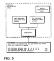
- the insertion program for a particular circuit board is stored on a suitable medium (a tape or floppy disc, for example) and is inputted to the Central Processing Unit for the machine ( Figure 3) through a serial communication port.
- the Computer Processing Unit also includes a pair of libraries which contain the centre spacing data for the magazines in the machine.
- the Last Program Magazine Data Library contains this data for the last insertion program in the non-volatile memory, and the Next Program Magazine Data Library contains this data for the next insertion program.
- a Comparator compares this data, and if there is any difference, presents the magazine data for the last and next programs on a CRT screen 38 in an adjacent format to confront the operator with any disparity and asks the operator whether the new program widths are correct.
- This presentation alerts the operator to the fact that one or more of the magazines or racks having one centre spacing should have been replaced by racks having the second centre spacing. If the operator has already made this change, this discrepancy can be ignored. If not, the operator will make the required change.
- the new program magazine data is compared with the last program magazine data retrieved from resident non-volatile memory (see the basic flowchart illustrated in Figure 4) and presents the alert referred to above if there are differences in the magazine data.
- the contents of the new program magazine data file is then entered into the old program magazine data file, overwriting the old contents. In effect, the new program magazine data now becomes the old program magazine data.
Landscapes
- Engineering & Computer Science (AREA)
- Manufacturing & Machinery (AREA)
- Microelectronics & Electronic Packaging (AREA)
- Operations Research (AREA)
- Supply And Installment Of Electrical Components (AREA)
Abstract
Description
- A dual in-line package (DIP) electronic component insertion machine inserts DIP components into a supported circuit board. Such a machine includes a plurality of component magazines having a number of raceways each containing a particular component having a specific centre spacing (C.S.). DIP components may have a variety of centre spacings (7.6 mm or 15.2 mm (.300 inch C.S. or .600 inch C.S.) for example), but conventionally, all raceways of a given magazine will hold components having the same centre spacing.
- In U.S. Patent No. 4,450,619, two locating pins on each magazine actuate associated switches to indicate to the computer control the centre spacing of the components contained in the magazine so that other portions of the machine can be adjusted to match the components in that magazine.
- It is an object of the present invention to provide a system for assuring that the component centre spacing of the magazines is correct.
- The present invention provides a machine for inserting dual in-line package (DIP) components having first and second centre spacings into a supported circuit board, the components being inserted during production runs in accordance with an insertion program comprising a plurality of magazines, at least one of the magazines adapted to contain components having the first centre spacing and, at least one of the magazines adapted to contain components having said second centre spacing, characterised in that the machine further comprises means (LAST PROGRAM MAGAZINE DATA LIBRARY) for storing the centre spacing data for the plurality of magazines adapted to contain components having the first and second centre spacings for the insertion program of the last production run, means (NEW PROGRAM MAGAZINE DATA LIBRARY) for storing the centre spacing data for the plurality of magazines adapted to contain components having the first and second centre spacings for the insertion program for the production run which is to be now started, means for comparing (COMPARATOR) the last data and the next data, and means for presenting the data of the last production run and of the production run which is now to be started when the data is different so that an operator will be alerted to change at least one of the magazines.
- The machine according to the invention for inserting dual in-line package components preferably further comprises first inserting means for inserting DIP components having the first centre spacing and second inserting means for inserting DIP components having the second centre spacing.
- The present invention will now be described with reference to the accompanying drawings, which illustrate a preferred embodiment of the invention.
- Referring to the drawings:
- Figure 1 is an oblique view of a portion of an embodiment of a DIP electronic component insertion machine according to the present invention;
- Figure 2 is an oblique schematic view of another portion of the machine;
- Figure 3 is a block diagram of another portion of the machine; and
- Figure 4 is a flowchart illustrating the operation of the machine.
- The component insertion machine has a pair of
insertion stations left hand station 10handles DIP components 14 having a first centre spacing (lead to lead spacing of 15.2 mm (.600 inch), for example) while theright hand station 12 handlesDIP components 16 having a smaller centre spacing (7.6 mm (.300 inch), for example). Each station has an insertion mechanism including a pair of grippers 18 which grip the component. The gripped component is lowered until the component leads 19 are partially inserted into receiving holes in a supportedcircuit board 20. The grippers release the partially inserted component and a pusher (not shown) is lowered fully to seat the component (the insertion heads operate sequentially following circuit board displacement to position the circuit board at the proper component receiving position). Once inserted, the associated cut andclinch mechanism 22 cuts the fully insertedleads 19 to size and crimps the leads to secure the component to the circuit board. - The electronic component insertion machine also has a plurality (five in the embodiment illustrated) of magazines 30 (Figure 2) each of which has a number of raceways (not shown). Each raceway contains like components and the components of all of the raceways in a particular magazine have the same centre spacing. A picker 32, which is displaceable along the
magazine 30 picks or accepts individual components from the raceways and transports and deposits the selected components in a feeder unit 36 (one for each insertion location) which feeds the component to the insertion head where it is gripped by the grippers 18. Details of a conventional picker and feeder are illustrated in U.S. Patent No. 4,450,619. - The insertion program for a particular circuit board is stored on a suitable medium (a tape or floppy disc, for example) and is inputted to the Central Processing Unit for the machine (Figure 3) through a serial communication port. The Computer Processing Unit also includes a pair of libraries which contain the centre spacing data for the magazines in the machine. The Last Program Magazine Data Library contains this data for the last insertion program in the non-volatile memory, and the Next Program Magazine Data Library contains this data for the next insertion program. A Comparator compares this data, and if there is any difference, presents the magazine data for the last and next programs on a
CRT screen 38 in an adjacent format to confront the operator with any disparity and asks the operator whether the new program widths are correct. This presentation alerts the operator to the fact that one or more of the magazines or racks having one centre spacing should have been replaced by racks having the second centre spacing. If the operator has already made this change, this discrepancy can be ignored. If not, the operator will make the required change. - Whenever an insertion program is transmitted to the computer, the new program magazine data is compared with the last program magazine data retrieved from resident non-volatile memory (see the basic flowchart illustrated in Figure 4) and presents the alert referred to above if there are differences in the magazine data. The contents of the new program magazine data file is then entered into the old program magazine data file, overwriting the old contents. In effect, the new program magazine data now becomes the old program magazine data.
Claims (2)
a plurality of magazines (30),
at least one of the magazines (30) adapted to contain components having the first centre spacing and,
at least one of the magazines (30) adapted to contain components having the second centre spacing,
characterised in that the machine further comprises means (LAST PROGRAM MAGAZINE DATA LIBRARY) for storing the centre spacing data for the plurality of magazines adapted to contain components having the first and second centre spacings for the insertion program of the last production run,
means (NEW PROGRAM MAGAZINE DATA LIBRARY) for storing the centre spacing data for the plurality of magazines adapted to contain components having the first and second centre spacings for the insertion program for the production run which is to be now started,
means for comparing (COMPARATOR) the last data and the next data, and
means (38) for presenting the data of the last production run and of the production run which is now to be started when the data is different so that an operator will be alerted to change at least one of the magazines.
first inserting means (22) for inserting DIP components having the first centre spacing, and
second inserting means (22) for inserting DIP components having the second centre spacing.
Applications Claiming Priority (2)
| Application Number | Priority Date | Filing Date | Title |
|---|---|---|---|
| US19334488A | 1988-05-19 | 1988-05-19 | |
| US193344 | 1988-05-19 |
Publications (2)
| Publication Number | Publication Date |
|---|---|
| EP0342818A2 true EP0342818A2 (en) | 1989-11-23 |
| EP0342818A3 EP0342818A3 (en) | 1991-04-17 |
Family
ID=22713262
Family Applications (1)
| Application Number | Title | Priority Date | Filing Date |
|---|---|---|---|
| EP19890304456 Withdrawn EP0342818A3 (en) | 1988-05-19 | 1989-05-03 | Electronic component insertion machine |
Country Status (4)
| Country | Link |
|---|---|
| EP (1) | EP0342818A3 (en) |
| JP (1) | JPH0218999A (en) |
| KR (1) | KR900019552A (en) |
| CA (1) | CA1286037C (en) |
Family Cites Families (3)
| Publication number | Priority date | Publication date | Assignee | Title |
|---|---|---|---|---|
| US4283836A (en) * | 1979-09-25 | 1981-08-18 | Universal Instruments Corporation | Multi-module dip transfer and insertion machine |
| US4450619A (en) * | 1981-06-09 | 1984-05-29 | Usm Corporation | Component inserting machine |
| KR900001090B1 (en) * | 1985-07-17 | 1990-02-26 | 후지쓰가부시끼가이샤 | Electronic parts inserting apparatus |
-
1989
- 1989-05-03 EP EP19890304456 patent/EP0342818A3/en not_active Withdrawn
- 1989-05-04 CA CA000598720A patent/CA1286037C/en not_active Expired - Lifetime
- 1989-05-15 JP JP1121294A patent/JPH0218999A/en active Pending
- 1989-05-18 KR KR1019890006651A patent/KR900019552A/en not_active Withdrawn
Also Published As
| Publication number | Publication date |
|---|---|
| CA1286037C (en) | 1991-07-09 |
| KR900019552A (en) | 1990-12-24 |
| EP0342818A3 (en) | 1991-04-17 |
| JPH0218999A (en) | 1990-01-23 |
Similar Documents
| Publication | Publication Date | Title |
|---|---|---|
| US7181307B2 (en) | Electronic circuit component mounting system, mounting control program, and system to prevent erroneous setting of electronic circuit components | |
| US5822210A (en) | Manufacturing management system having SMT line | |
| EP0476577B1 (en) | Parts supply device, parts supply method and parts managing apparatus | |
| EP0618517B1 (en) | Programmable controller and SFC program executing method using the programmable controller | |
| HK1010066B (en) | Programmable controller and sfc program executing method using the programmable controller | |
| US4947546A (en) | Method of making a cable assembly | |
| EP0342818A2 (en) | Electronic component insertion machine | |
| US7198260B2 (en) | Method for synchronizing a number of paper feeding channels of a paper processing system | |
| US3744031A (en) | Method and apparatus for recording and verifying magnetic tape programs for machine tools | |
| US5371940A (en) | Pallet arranging system | |
| EP1137335B1 (en) | Production line for mounting electronic components | |
| JPS6241439B2 (en) | ||
| US7025262B2 (en) | Component control in a placement machine | |
| JPH10113836A (en) | Method and apparatus for checking used tools of NC machine tool | |
| JP2516913B2 (en) | Parts replenishment method | |
| US7089074B2 (en) | Host feeder setup validation | |
| JPH104294A (en) | Electronic component insertion device | |
| US5305524A (en) | Method for controlling different component inserting system | |
| JPS634315B2 (en) | ||
| JP2001015984A (en) | Parts management system | |
| EP0342817A2 (en) | Electronic component insertion machine | |
| JPH0775808B2 (en) | Electronic component automatic mounting machine | |
| EP4274399A1 (en) | Method for delivering components in feeder cassettes, delivery system, computer program product and computer-readable medium | |
| JPH05181517A (en) | Positioning device for parts supply section of automatic assembly machine | |
| JP3223011B2 (en) | Parts embedding machine |
Legal Events
| Date | Code | Title | Description |
|---|---|---|---|
| PUAI | Public reference made under article 153(3) epc to a published international application that has entered the european phase |
Free format text: ORIGINAL CODE: 0009012 |
|
| AK | Designated contracting states |
Kind code of ref document: A2 Designated state(s): DE FR GB |
|
| RAP1 | Party data changed (applicant data changed or rights of an application transferred) |
Owner name: EMHART INDUSTRIES, INC. |
|
| RAP1 | Party data changed (applicant data changed or rights of an application transferred) |
Owner name: DYNAPERT INC. |
|
| PUAL | Search report despatched |
Free format text: ORIGINAL CODE: 0009013 |
|
| RAP1 | Party data changed (applicant data changed or rights of an application transferred) |
Owner name: EMHART INC. |
|
| AK | Designated contracting states |
Kind code of ref document: A3 Designated state(s): DE FR GB |
|
| STAA | Information on the status of an ep patent application or granted ep patent |
Free format text: STATUS: THE APPLICATION IS DEEMED TO BE WITHDRAWN |
|
| 18D | Application deemed to be withdrawn |
Effective date: 19911018 |