EP0342776B1 - Vacuum die mount - Google Patents
Vacuum die mount Download PDFInfo
- Publication number
- EP0342776B1 EP0342776B1 EP89302153A EP89302153A EP0342776B1 EP 0342776 B1 EP0342776 B1 EP 0342776B1 EP 89302153 A EP89302153 A EP 89302153A EP 89302153 A EP89302153 A EP 89302153A EP 0342776 B1 EP0342776 B1 EP 0342776B1
- Authority
- EP
- European Patent Office
- Prior art keywords
- die
- cylinder
- vacuum
- die cylinder
- valve
- Prior art date
- Legal status (The legal status is an assumption and is not a legal conclusion. Google has not performed a legal analysis and makes no representation as to the accuracy of the status listed.)
- Expired - Lifetime
Links
Images



Classifications
-
- B—PERFORMING OPERATIONS; TRANSPORTING
- B41—PRINTING; LINING MACHINES; TYPEWRITERS; STAMPS
- B41F—PRINTING MACHINES OR PRESSES
- B41F27/00—Devices for attaching printing elements or formes to supports
- B41F27/12—Devices for attaching printing elements or formes to supports for attaching flexible printing formes
-
- B—PERFORMING OPERATIONS; TRANSPORTING
- B26—HAND CUTTING TOOLS; CUTTING; SEVERING
- B26D—CUTTING; DETAILS COMMON TO MACHINES FOR PERFORATING, PUNCHING, CUTTING-OUT, STAMPING-OUT OR SEVERING
- B26D7/00—Details of apparatus for cutting, cutting-out, stamping-out, punching, perforating, or severing by means other than cutting
- B26D7/26—Means for mounting or adjusting the cutting member; Means for adjusting the stroke of the cutting member
- B26D7/2614—Means for mounting the cutting member
-
- B—PERFORMING OPERATIONS; TRANSPORTING
- B26—HAND CUTTING TOOLS; CUTTING; SEVERING
- B26F—PERFORATING; PUNCHING; CUTTING-OUT; STAMPING-OUT; SEVERING BY MEANS OTHER THAN CUTTING
- B26F1/00—Perforating; Punching; Cutting-out; Stamping-out; Apparatus therefor
- B26F1/38—Cutting-out; Stamping-out
- B26F1/40—Cutting-out; Stamping-out using a press, e.g. of the ram type
- B26F1/42—Cutting-out; Stamping-out using a press, e.g. of the ram type having a pressure roller
-
- B—PERFORMING OPERATIONS; TRANSPORTING
- B26—HAND CUTTING TOOLS; CUTTING; SEVERING
- B26D—CUTTING; DETAILS COMMON TO MACHINES FOR PERFORATING, PUNCHING, CUTTING-OUT, STAMPING-OUT OR SEVERING
- B26D7/00—Details of apparatus for cutting, cutting-out, stamping-out, punching, perforating, or severing by means other than cutting
- B26D7/26—Means for mounting or adjusting the cutting member; Means for adjusting the stroke of the cutting member
- B26D2007/2607—Means for mounting or adjusting the cutting member; Means for adjusting the stroke of the cutting member for mounting die cutters
-
- Y—GENERAL TAGGING OF NEW TECHNOLOGICAL DEVELOPMENTS; GENERAL TAGGING OF CROSS-SECTIONAL TECHNOLOGIES SPANNING OVER SEVERAL SECTIONS OF THE IPC; TECHNICAL SUBJECTS COVERED BY FORMER USPC CROSS-REFERENCE ART COLLECTIONS [XRACs] AND DIGESTS
- Y10—TECHNICAL SUBJECTS COVERED BY FORMER USPC
- Y10S—TECHNICAL SUBJECTS COVERED BY FORMER USPC CROSS-REFERENCE ART COLLECTIONS [XRACs] AND DIGESTS
- Y10S101/00—Printing
- Y10S101/46—Printing operation controlled by code indicia on printing plate or substate
-
- Y—GENERAL TAGGING OF NEW TECHNOLOGICAL DEVELOPMENTS; GENERAL TAGGING OF CROSS-SECTIONAL TECHNOLOGIES SPANNING OVER SEVERAL SECTIONS OF THE IPC; TECHNICAL SUBJECTS COVERED BY FORMER USPC CROSS-REFERENCE ART COLLECTIONS [XRACs] AND DIGESTS
- Y10—TECHNICAL SUBJECTS COVERED BY FORMER USPC
- Y10T—TECHNICAL SUBJECTS COVERED BY FORMER US CLASSIFICATION
- Y10T279/00—Chucks or sockets
- Y10T279/11—Vacuum
-
- Y—GENERAL TAGGING OF NEW TECHNOLOGICAL DEVELOPMENTS; GENERAL TAGGING OF CROSS-SECTIONAL TECHNOLOGIES SPANNING OVER SEVERAL SECTIONS OF THE IPC; TECHNICAL SUBJECTS COVERED BY FORMER USPC CROSS-REFERENCE ART COLLECTIONS [XRACs] AND DIGESTS
- Y10—TECHNICAL SUBJECTS COVERED BY FORMER USPC
- Y10T—TECHNICAL SUBJECTS COVERED BY FORMER US CLASSIFICATION
- Y10T83/00—Cutting
- Y10T83/04—Processes
-
- Y—GENERAL TAGGING OF NEW TECHNOLOGICAL DEVELOPMENTS; GENERAL TAGGING OF CROSS-SECTIONAL TECHNOLOGIES SPANNING OVER SEVERAL SECTIONS OF THE IPC; TECHNICAL SUBJECTS COVERED BY FORMER USPC CROSS-REFERENCE ART COLLECTIONS [XRACs] AND DIGESTS
- Y10—TECHNICAL SUBJECTS COVERED BY FORMER USPC
- Y10T—TECHNICAL SUBJECTS COVERED BY FORMER US CLASSIFICATION
- Y10T83/00—Cutting
- Y10T83/081—With randomly actuated stopping means
- Y10T83/088—Responsive to tool detector or work-feed-means detector
- Y10T83/089—Responsive to tool characteristic
-
- Y—GENERAL TAGGING OF NEW TECHNOLOGICAL DEVELOPMENTS; GENERAL TAGGING OF CROSS-SECTIONAL TECHNOLOGIES SPANNING OVER SEVERAL SECTIONS OF THE IPC; TECHNICAL SUBJECTS COVERED BY FORMER USPC CROSS-REFERENCE ART COLLECTIONS [XRACs] AND DIGESTS
- Y10—TECHNICAL SUBJECTS COVERED BY FORMER USPC
- Y10T—TECHNICAL SUBJECTS COVERED BY FORMER US CLASSIFICATION
- Y10T83/00—Cutting
- Y10T83/141—With means to monitor and control operation [e.g., self-regulating means]
- Y10T83/148—Including means to correct the sensed operation
-
- Y—GENERAL TAGGING OF NEW TECHNOLOGICAL DEVELOPMENTS; GENERAL TAGGING OF CROSS-SECTIONAL TECHNOLOGIES SPANNING OVER SEVERAL SECTIONS OF THE IPC; TECHNICAL SUBJECTS COVERED BY FORMER USPC CROSS-REFERENCE ART COLLECTIONS [XRACs] AND DIGESTS
- Y10—TECHNICAL SUBJECTS COVERED BY FORMER USPC
- Y10T—TECHNICAL SUBJECTS COVERED BY FORMER US CLASSIFICATION
- Y10T83/00—Cutting
- Y10T83/929—Tool or tool with support
- Y10T83/9372—Rotatable type
-
- Y—GENERAL TAGGING OF NEW TECHNOLOGICAL DEVELOPMENTS; GENERAL TAGGING OF CROSS-SECTIONAL TECHNOLOGIES SPANNING OVER SEVERAL SECTIONS OF THE IPC; TECHNICAL SUBJECTS COVERED BY FORMER USPC CROSS-REFERENCE ART COLLECTIONS [XRACs] AND DIGESTS
- Y10—TECHNICAL SUBJECTS COVERED BY FORMER USPC
- Y10T—TECHNICAL SUBJECTS COVERED BY FORMER US CLASSIFICATION
- Y10T83/00—Cutting
- Y10T83/929—Tool or tool with support
- Y10T83/9457—Joint or connection
- Y10T83/9464—For rotary tool
Definitions
- This invention relates in general to vacuum mounting of dies on die cylinders. It is particularly applicable to mounting cutting dies in container blank processing machinery, for example rotary die cutting apparatus used in the production of corrugated paperboard carton blanks.
- the present invention is primarily concerned with improving the above approach for vacuum mounting wooden cutting dies.
- vacuum is meant the use of less than atmospheric pressure.
- the present invention is also concerned with providing an improved approach and system for vacuum mounting rigid, and particularly heavy, dies on die cylinders.
- Various features of the present invention are the employment of a special collapsible seal preferably around the edge of the die, the employment of a key on the die shell engageable in a keyway in the die cylinder, the employment of balls in the surface of the die cylinder to function both as a ball conveyer and vacuum distribution valves, and the employment of sensing systems to locate whether a correct die is present.
- die mounting apparatus comprising a rotatable die cylinder having a die mounting surface, means for connecting the interior of said die cylinder to a source of vacuum, at least one valve unit mounted in said die cylinder, said valve unit having an actuating member protruding above said die mounting surface when the valve is closed, depression of said actuating member opening the valve for placing said die cylinder interior in communication with said die mounting surface, a die mounted on said die mounting surface over said actuating member and being held on said surface in use by vacuum applied below said die through said valve unit, said actuating member being depressed by said die, and a seal sandwiched between said die and said die mounting surface; the apparatus being characterized by said seal defining a closed area on the underside of said die and to which area the vacuum is in use applied, and by said seal comprising at least one elongate element having a lengthwise direction and a width transverse to said lengthwise direction, said element having a bubble formed intermediate its width and extending in said length
- the elongate element comprises two superimposed strips; one of the strips may be flat and the other of the strips may be deformed to form the bubble.
- valve actuating members are rotatable spherical balls on which the die can roll when being positioned on the die cylinder.
- Check valve means may be disposed in said connecting means for preventing flow of air from the vacuum source into the die cylinder interior in the event of failure of the vacuum source.
- the apparatus further comprises a motor for drivingly rotating said die cylinder about an axis, means for controlling said motor, first and second sensor means connected to said controlling means, for transmitting and receiving light, a first light reflector mounted on said die cylinder, a second light reflector mounted on said die, said second reflector being spaced from said first reflector in a direction parallel to said axis, said first sensor means functioning via said controlling means to switch said motor off if said first sensor means senses reflected light from said first reflector, and said second sensor means functioning via said controlling means to switch said motor off if said second sensor means does not sense reflected light from said second reflector.
- any form of electromagnetic waves may be transmitted, reflected and received to perform this sensing function.
- the apparatus may be provided with a selector switch manually actuatable between a vacuum mode, when the vacuum means is to be operative, and a standard mode when the vacuum means is rendered inoperative and conventional boltdown dies are used.
- the collapsible seal comprises an air bubble.
- Further aspects of the present invention also provide methods of sensing the presence or absence of reflected signals from reflectors on a cutting die intended for vacuum mounting and a rotatable die cylinder adapted to vacuum mount cutting dies.
- the drive to the die cylinder being switched off if a wrong reflected signal is received or a correct one is not received.
- the reflectors are light reflectors and the sensing detects light beams reflected by the light reflectors; however, other types of reflectors, wave forms and sensing could be used.
- the preferred apparatus system is illustrated in Figs. 1, 2 and 3, the preferred cutting and/or creasing die is shown in Figs. 2 through 5 with the preferred peripheral vacuum sealing strip shown in Figs. 6 and 7, and the preferred vacuum distribution valve for the die cylinder surface is shown in Figs. 10 to 13.
- Fig. 1 shows a die cutting and/or creasing section 20 of, for example, a flexographic printer rotary die cutter machine used in the production of container blanks from sheets of corrugated paperboard.
- a die cylinder 22 and anvil cylinder 24 have journals 26 rotatably mounted in spaced-apart end frames 28, 30.
- the cylinders 22, 24 are parallel and spaced vertically apart with a gap 32 therebetween to enable cutting rules on the die, when mounted on the die cylinder, to penetrate the correct distance into a resilient cover 34 on the anvil cylinder 24.
- An electric main drive motor 36 drivingly rotates the die cylinder 22 through a gear transmission 38 (illustrated by a broken line), which may be the gear train of a conventional flexographic rotary die cutter having feed, print, and die cutter sections as well understood by those skilled in the art.
- the anvil cylinder 24 is driven from the die cylinder 22 via gearing 40 (illustrated by a broken line).
- the die cylinder 22 is hollow and its interior is connected via the righthand journal 26, which is hollow, a check valve 42, and piping 44 to a source of vacuum 46 in the form of a regenerating vacuum blower driven by an electric motor of suitable horsepower.
- a vacuum gauge 48 indicates the vacuum being drawn inside the die cylinder 22.
- the die cylinder 22 which is shown in Fig. 1 without a die mounted thereon, has an axially extending surface groove 50 extending the length of the roll 22 and parallel to the axis of rotation thereof, the groove 50 forming a keyway.
- a light reflector 52 is mounted in the bottom of the groove 50 at a location displaced a short distance axially to the right of the center plane 54 indicated by a broken line.
- a pair of photoelectric sensor beam units 56, 58 are wired to a control circuitry unit 60 of the main drive motor 36. These sensor units 56, 58 are mounted on a frame cross-member between the end frames 28, 30 and above the die cylinder 22.
- Each sensor unit 56, 58 transmits a beam of light and measures the intensity of the light from this beam which is reflected back to the respective sensor unit.
- the sensor unit 56 is positioned to the righthand side of the plane 54 to project light onto and receive reflected light back from the reflector 52; this occurring each time the reflector passes the sensor unit 56 as the die cylinder 22 is rotated with no die covering the reflector 52.
- the other sensor unit 58 is positioned in line with the central plane 54 for cooperation with a second reflector mounted on a trailing edge of a die as will be explained later.
- Photoelectric sensor beam units suitable for this purpose are supplied by Banner Engineering Corporation of 9714 10th Ave., No., Minneapolis, Mn 55441 under the designation Banner MINI-BEAM series SM2A312LV 2-wire AC retroreflective sensor. It should be understood that other types of sensing means may be employed, such as commercially available sonic transmitter/sensor units, infra-red transmitter/sensor units, or magnetic transmitter/sensor units with suitably appropriate reflectors, all of which sensing systems are operable to provide input signals to the control circuitry 60.
- Fig. 2 shows the inside of a cutting and/or creasing die 62 constructed according to the invention.
- the die 62 has a curved shell 64 formed from thick plywood, the shell 64 being curved to fit on the die cylinder 22. Adjacent a trailing edge 66 of the die is mounted a key 68.
- the elongate key 68 is made of aluminum (but may be made of steel or plastic), extends lengthwise parallel to the edge 66, and is rigidly secured to the shell 64 centrally between the ends thereof by five bolts 70.
- the key 68 projects inwardly and locates in the groove 50 of the die cylinder 22 as will be explained later.
- Adjacent the ends of the die 62 are cutouts 72 to serve as handles for carrying and manipulating the die 62 during mounting on and removal from the die cylinder 22.
- a continuous vacuum sealing strip 74 surrounds each handle cutout 72 on the interior side of the die 62.
- a peripheral vacuum sealing strip or gasket 76 extends completely around the periphery of the interior surface of the die 62, but spaced a short distance in from the peripheral edges of the shell 64. This sealing strip 76 is made up from two longitudinal strips 78, 80 which extend the full length of the shell 64, and two transverse strips 82 which extend between and connect the two longitudinal strips 78, 80.
- the longitudinal strip 78 passes on the inside of the key 68, the key being outside the area sealed off (in use) by the peripheral sealing strip 76.
- the handle cutouts 72 are surrounded by sealing strips 74, the cutouts 72 can be outside (as shown) or inside the area surrounded by the peripheral sealing strip 76.
- Two bolt holes 84 are located adjacent the leading edge 86 of die 62, preferably adjacent the axial ends thereof.
- Fig. 3 is a perspective view, partly broken away and simplified, illustrating the die 62 mounted on the die cylinder 22.
- the die cylinder 22 is rotated in use in the direction of the arrow 88.
- the trailing edge 66 of the die is located rearwardly of the groove 50 with the die key 68 (not visible in Fig. 3) engaged in the groove or keyway 50.
- Two bolts 90 which extend through the bolt holes 84 (Fig. 2), secure the leading edge of the die 62 to the die cylinder 22, the bolts 90 being screwed into screw-threaded blind bores in the die cylinder 22.
- the keyway groove 50 locates the die 62 circumferentially, and the bolts 90 preferably locate the die axially on the die cylinder 22, although a scribeline on die 62 may be aligned with the center plane 54 on die cylinder 22 to locate the die axially .
- the die 62 has serrated cutting rules 92 mounted thereon as is conventional for a cutting die. Creasing rules may also be conventionally mounted in addition to or in place of the cutting rules.
- the rules 92 pass tightly through slots in the shell 64 and rest directly on the metal surface of the die cylinder 22, as is well known.
- a second reflector 94 is mounted adjacent the trailing edge 66 of the die.
- This reflector 94 due to its axial location on the die 62 and the axial location of the die 62 on the die cylinder 22 by the bolts 90, rotates in the center plane 54 in Fig. 1.
- the reflector 94 which may comprise a plurality of prisms 96, reflects light back to the photoelectric sensor 58.
- the die cylinder 22 is hollow and has an outer cylindrical wall 98.
- a plurality of valve units 100 are secured in radial bores 102 through the cylindrical wall 98.
- Each valve unit has a depressible valve member in the form of a ball which, when depressed by the die 62, places the underside of the die 62 in communication with the vacuum drawn in the interior of the die cylinder 22 ; these valve units 100 will be described in greater detail later with reference to Figs. 10 to 13.
- the valve units are located in rows extending axially along the die cylinder 22, alternate rows 104, 106 being staggered axially with the valve units 100 of the rows 106 being axially halfway between those of the rows 104.
- the rows 104, 106 are spaced apart equally completely around the periphery of the die cylinder 22. There are no valve units in the keyway 50.
- the die cylinder 22 is provided with a plurality of threaded blind bores spaced around and along its curved surface to enable different size dies 62 to be used and accommodate the different positions of the hold-down bolts 90 inserted through the bolt holes 84.
- These threaded bores are preferably provided all over the surface of the die cylinder 22 and in a pattern that will accept the many hold-down bolts of conventional bolted dies, such pattern being indicated in broken lines 107 in Figs. 4 and 5. This then enables the same die cylinder 22 to be used at choice with either vacuum mounted dies 62 or conventional standard bolted dies. This is particularly advantageous if a user needs time to convert standard dies to vacuum mounted dies.
- the threaded blind bores 107 should not be equally spaced circumferentially between rows 104 and 106 of depressible vacuum valves 100. This is indicated in Figs. 4 and 5, and reduces the possibility of the edge of the die actuating a valve 100 since it is common practice for a die maker to cut a die evenly between the bolt holes.
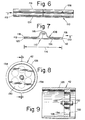
- Figs. 6 and 7 show in greater detail the construction of the gasket strips 78, 80, 82 making up the peripheral vacuum seal 76 in Fig. 2.
- Each strip 78, 80, 82 comprises an upper film strip 108 secured to a lower film strip 110 by a thin layer of adhesive 112.
- the lower film strip 110 is flat and has a width 114, which is also the width of the gasket strip.
- the upper film strip 108 is substantially wider than the strip 110, but is deformed upwardly at its central portion to form a tunnel 116 so that the effective width of the so deformed upper strip 108 is 114, the same as the actual width of the lower strip 110; this can be clearly seen in Fig. 7.
- the outer longitudinal edges 118 of the deformed upper strip are superimposed over the corresponding outer longitudinal edges 120 of the flat lower strip 110.
- the adhesive 112 bonds the portions of the upper strip 108 on each side of the tunnel 116 to outer portions of the lower strip 110. There is no adhesive on the mid portion 122 of the lower strip 110 forming the base of the tunnel 116.
- the lower surface 124 of the lower strip 110 is covered with a layer of self-adhering adhesive by which the gasket strip is secured in place to the interior surface of the die 62 as in Fig. 2.
- the strips 108 and 110 are made of urethane film.
- the overall width 114 of the gasket strip is preferably one inch (2.54cm), the width and height of the tunnel 116 being preferably 0.25 inch (0.64 cm) and 0.2 inch (0.51 cm), respectively. It will be appreciated that the width of the tunnel 116 is approximately one third of the overall width of the gasket strip, and the height of the tunnel 116 is of the order of half the width of the tunnel at its base and equal to the mean width of the tunnel above its base. The height of the tunnel may be about one eighth to one quarter of the overall width of the gasket strip.
- the strips 108 and 110 are only a few thousandths of an inch (several thousandths of a centimeter) thick. In this way the tunnel 116 forms a readily deformable "bubble" which normally stands upright but can easily be flattened.
- the ends of the tunnel 116 are not sealed, but are preferably left open as shown in Fig. 7. In this way, air is not trapped and compressed in the tunnel when compressed between the die and the die cylinder; this allows the tunnel to completely and readily collapse.
- the inherent resiliency of the tunnel 116 enables it to return to its raised tunnel shape when the die is removed from the die cylinder.
- Figs. 8 and 9 show details of the check valve 42 in Fig. 1.
- the check valve 42 has a hollow cylindrical body 126 across the interior of which extends transversely a seat plate 128.
- a circular disc valve member 130 of resiliently deformable sheet material is secured at its center by a bolt 132 to the center of the plate 128 and covers six apertures 134 through the plate 128 spaced around the bolt 132.
- the disc 132 is on the outer side of the seat plate 128, so allowing flow of air out of the die cylinder (to the right in Figs. 9 and 1) but preventing flow of air into the die cylinder from the piping 44 (Fig. 1).
- the check valve 42 functions to allow the vacuum blower 46 to draw a vacuum inside the die cylinder 22; on the other hand, should the vacuum blower 46 or vacuum system fail for any reason while a vacuum exists inside the die cylinder 22, then the disc valve member 130 would close the apertures 134 and prevent air entering the die cylinder from the piping 44 so preserving the vacuum inside the die cylinder.
- Fig. 4 shows an end elevational view (in the direction of the arrow 8 in Fig. 1) of the die 62 mounted on the die cylinder 22.
- the key 68 can be seen fully engaged in the keyway 50 with the reflector 52 in the bottom of the keyway 50 just below the radially inner surface of the key 68.
- the lower portion of the forward face (in the direction of rotation of the arrow 88) of the key 68 is downwardly and rearwardly tapered at 136 to facilitate location and entry of the key 68 into the keyway 50.
- the key 68 is a loose fit in the keyway 68; this enables the key to move forwardly to facilitate insertion of the leading edge bolts 90 when the die 62 is initially being manually positioned and mounted on the die cylinder 22.
- the key 68 may move rearwardly in the keyway 50; when the die cylinder is then rotated, the trailing edge of the key 68 abuts the trailing wall of the keyway 50 to accurately position the trailing edge of the die 62 relative to the periphery of the die cylinder 22.
- the peripheral gasket 76 (Fig. 2) bridges any gaps between the die and the die cylinder, valve units 100 (Fig. 3) below the die are actuated, and vacuum from inside the die cylinder 22 is applied to the underside of the die 62 inside the area surrounded by the peripheral gasket 76 (Fig.
- valve units 100 are indicated by broken lines extending radially outside the die cylinder, there being thirteen spaced apart rows of valve units around the periphery of the die cylinder. In each row, the valve units are spaced axially approximately four inches (10 cm) apart.
- Fig. 5 is a similar view to Fig. 4 but additionally shows a second die 138 mounted on the die cylinder 22.
- This second die 138 does not have a key and the die cylinder does not have a second keyway for this die.
- This second die is initially secured to the die cylinder by four corner bolts 140, 142 screwed into the die cylinder 22, two bolts 140 (only one being visible in broken lines) being adjacent the trailing edge of the die 138, and two bolts 142 (only one visible) being adjacent its leading edge.
- the valve units 100 Fig.
- the second die 138 has a peripheral gasket on its underside similar to the peripheral gasket 76 in Fig. 2 of the die 62.
- the trailing edge of the second die 138 abuts and is rearwardly positioned by the leading edge 86 of the keyed die 62.
- a third, and if desired a fourth, die could be added to the die cylinder in a similar manner to the second die 138.
- corner bolts initially hold the die in approximate position, and then the application of vacuum firmly draws the die against and into conformity with the surface of the die cylinder.
- Figs. 10 through 13 illustrate one of the valve units 100.
- the valve unit has a cylindrical tube-like body 144 having an inturned tapered flange 146 at the top and a hollow plug 148 at the bottom.
- the valve bodies 144 are secured by adhesive in the radial bores 102 (see Fig. 3) in the die cylinder 22 with the upper end surface of the flange 146 flush with the outer surface of the die cylinder 22.
- An actuating member in the form of a solid spherical ball 150 is located in the upper portion of the valve body 144 with less than half the ball 150 protruding through the center of the flange 146.
- the radially inward tapering of the flange 146 forms a knife edge valve seat 152 against which the upper portion of the ball 150 engages to close the valve.
- a hollow tubular member 154 is telescopically mounted over a guide and support post 156.
- the tubular member 154 has a closed top 158 and a coil spring is compressed between this top 158 and a collar 162 on the post 156.
- the spring 160 is completely enclosed inside the tubular member 154 and urges the top of the member 154 against the ball 150 so resiliently urging the ball 150 against its seat 152.
- the upper surface of the top 158 is formed as a concave cavity 164 to conform to the surface of the ball 150, this facilitating rolling of the ball when contacted by a die.
- the tubular member 154 has radially outwardly extending fins 166 (see Fig.
- the upper interior portion 168 of the plug 148 is downwardly and inwardly tapered until it merges into a cylindrical lower portion 170.
- the post 156 is integrally connected to and supported by the plug 148 in the region of upper portion 168 and its junction with the cylindrical lower portion 170; part of this integral connection is a fin 172 (see Figs. 11 and 13) which slidably engages in a slot 174 in the lower portion of the tubular member 154.
- the valve is normally closed with the spring 160 resiliently urging the ball 150 against its knife edge seat 152.
- the ball 150 which protrudes proud of the surface of the die cylinder 22
- the ball 150 is moved inwardly into the valve body 144 away from its seat 152.
- this clear and straight-through passage between the tubular member 154 and the valve body 144 offers minimum resistance to air flow, virtually no changes in direction of air flow, and minimizes places in which paper debris, etc. in the air flow could become hung-up and clog the valve unit.
- valve unit In conjunction with the ball member 150 and the knife edge valve seat 152, the valve unit is essentially self-clearing of paper debris etc. In this respect it should also be noted that as the spring 160 is totally enclosed, the spring is not exposed to the air flow through the valve unit and so cannot present any risk of trapping or becoming clogged with paper debris etc.
- the balls 150 can have a diameter in the range 0.125 to 0.5 inches (0.318 to 1.27 cm), preferably less than 0.375 inch (0.952 cm), for example, 0.25 inch (0.635 cm).
- the machine In operation, to mount a die the machine is stopped, that is, the main drive motor 36 and the vacuum blower 46 are stopped.
- the selected die 62 is manually picked-up via the handle cutouts 72 and placed on the die cylinder 22 with the key 68 engaging in the keyway 50 as previously discussed.
- the die 62 is then slid axially along the die cylinder until the bolt holes 84 are aligned with corresponding screw threaded bores in the die cylinder and the reflector 94 on the die 62 is in the central plane 54 in alignment with the sensor unit 58.
- the securing bolts 90 are then carefully inserted through the bolt holes 84 and tightened into the die cylinder
- the peripheral play or slop of the key 68 in the keyway 50 facilitates this operation, so enabling it to be performed quicker.
- the ball shaped actuating members 150 of the valve units 100 facilitate axial movement of the die 62 along the die cylinder during this set-up operation due to the balls 150 rotating and functioning as a ball conveyor. This further contributes to saving setup time, particularly as some dies are very heavy and difficult to maneuver, especially so when trying to make minute adjustments to align the bolt holes 84 with the appropriate bores in the die cylinder.
- the key 68 and the pair of leading edge bolts 90 will hold the die 22 on the die cylinder until the vacuum is turned on; however, due to distortion in the wooden shell 64 of the die, the die will not conform to the surface of the die cylinder 22 and will tend to be spaced therefrom. However, due to the height of the tunnel or bubble 116 in the peripheral gasket 76, preferably 0.125 to 0.25 inch (0.317 to 0.635 cm), this gasket will tend to bridge the varying gap between the die 62 and the die cylinder around the periphery of the die. Further, at least some of the valve units 100 covered by the die 62 will have their ball actuating members 150 depressed or partially depressed.
- a switch (not shown) is moved by the operator from a standard mode for conventional bolted-on dies to a vacuum mode for vacuum mounted dies. Then the motor of the vacuum blower 46 is turned on by a switch (not shown). The main drive motor 36 is switched on and the die cylinder 22, together with the anvil cylinder 24, commence to rotate.
- the fail safe die sensor system immediately functions to sense that the correct type of die is present, and if not, to shut the machine down within two revolutions of the die cylinder 22 from start-up of the main drive motor 36. There are two aspects to the die sensor system.
- the control circuitry 60 switches the main drive motor "off".
- the control circuitry 60 switches the main drive motor "off".
- the first situation i.e. lack of sensing by the unit 58, will occur if an incorrect die is mounted or a correct die is axially incorrectly located.
- the second situation i.e. sensing by the unit 56, will occur when a die is not keyed in the keyway 50 as it should be when the vacuum mode is selected; in this situation the machine is stopped to check whether a non-vacuum mount die has only been bolted for vacuum mounting.
- a further fail safe system is incorporated to sense insufficient vacuum, including loss of vacuum.
- a pressure transducer 176 (see Fig. 1), mounted on the end frame 30, is connected to sense the air pressure in the piping 44 at the location of the vacuum gauge 48. If the machine is in the vacuum mode and the transducer 176 senses insufficient vacuum, namely less than 75 inches (190 cm) of water below atmospheric pressure, the transducer 176 via the control circuitry 60 shuts down the whole machine, i.e. it switches off the main drive motor 36 and the vacuum blower 46. It should be noted that when the vacuum blower 46 is switched off, the check valve 42 will retain whatever vacuum is inside the die cylinder 22. This keeps the die in place on the die cylinder while the cylinder is braking to a stop should vacuum fail during operation.
- peripheral gasket 76 would tend to deflect the wooden shell 64 of the die 22, preventing the die being held closely to the die cylinder, and tending to cause the wooden shell or die board 64 to crack. Also, the cutting rules would tend to perform inaccurately.
- a tunnel or "bubble" gasket strip 108, 110, 116 this new gasket not only being able to initially seal substantial gaps between the die board and the die cylinder, but also being capable of being totally flattened and becoming an ultra thin gasket when the vacuum is applied, particularly when the air in the bubble is expelled from the tunnel 116.
- Any bridge holes or the like through the wooden die shell 64 should preferably be caulked with latex paint and then painted over on the inside of the die with thinner latex paint. Also, the cutting and creasing rules should preferably be painted around with latex on the inside of the die shell to improve sealing around these rules.
- the two leading edge bolts 90 may be retained by suitable cages in their bolt holes 84 in the die.
Landscapes
- Life Sciences & Earth Sciences (AREA)
- Forests & Forestry (AREA)
- Engineering & Computer Science (AREA)
- Mechanical Engineering (AREA)
- Making Paper Articles (AREA)
- Perforating, Stamping-Out Or Severing By Means Other Than Cutting (AREA)
- Moulds For Moulding Plastics Or The Like (AREA)
Description
- This invention relates in general to vacuum mounting of dies on die cylinders. It is particularly applicable to mounting cutting dies in container blank processing machinery, for example rotary die cutting apparatus used in the production of corrugated paperboard carton blanks.
- It is well known to mount dies on die cylinders for carrying out various operations on paperboard sheets, e.g. cutting, creasing, printing etc. Some of these dies are heavy and formed with a rigid base shell, e.g. a curved wooden die board. Such rigid dies are mounted on and secured to an appropriate die cylinder by bolts. A large number of bolts are inserted through bolt holes all over the surface of the die, and these bolts screwed into screw-threaded bores in the die cylinders to draw the die against and into general conformity with the die cylinder.
- Due to distortion of such wooden die boards, after inserting the first one or two bolts, it often becomes increasingly difficult to align subsequent bolt holes in the die with the screw-threaded bores in the die cylinder. Due to the weight and awkwardness of these wooden die boards, particularly the larger ones, the process of inserting and then tightening the large number of mounting bolts is usually time consuming and somewhat tedious. Subsequently, to remove such dies, it is also fairly time consuming to loosen and remove the large number of mounting bolts. US-A- 4,683,822 of the present Applicant discloses, inter alia, an arrangement for vacuum mounting rigid cutting dies on die cylinders, comprising a rotatable cylinder, a die mounted on an external surface of the cylinder, and a source of vacuum. This approach, for vacuum mounting wooden die boards, although very promising, still required further refinement to improve its acceptability commercially.
- The present invention is primarily concerned with improving the above approach for vacuum mounting wooden cutting dies. By "vacuum" is meant the use of less than atmospheric pressure.
- The present invention is also concerned with providing an improved approach and system for vacuum mounting rigid, and particularly heavy, dies on die cylinders.
- Various features of the present invention are the employment of a special collapsible seal preferably around the edge of the die, the employment of a key on the die shell engageable in a keyway in the die cylinder, the employment of balls in the surface of the die cylinder to function both as a ball conveyer and vacuum distribution valves, and the employment of sensing systems to locate whether a correct die is present. These and other features, individually or in combination, contribute to achieving the objects of the present invention.
- Accordingly, there is provided by one aspect of the present invention, die mounting apparatus comprising a rotatable die cylinder having a die mounting surface, means for connecting the interior of said die cylinder to a source of vacuum, at least one valve unit mounted in said die cylinder, said valve unit having an actuating member protruding above said die mounting surface when the valve is closed, depression of said actuating member opening the valve for placing said die cylinder interior in communication with said die mounting surface, a die mounted on said die mounting surface over said actuating member and being held on said surface in use by vacuum applied below said die through said valve unit, said actuating member being depressed by said die, and a seal sandwiched between said die and said die mounting surface; the apparatus being characterized by said seal defining a closed area on the underside of said die and to which area the vacuum is in use applied, and by said seal comprising at least one elongate element having a lengthwise direction and a width transverse to said lengthwise direction, said element having a bubble formed intermediate its width and extending in said lengthwise direction, said bubble being flattened between said die and said die mounting surface when said vacuum is applied to said closed area.
- Preferably, the elongate element comprises two superimposed strips; one of the strips may be flat and the other of the strips may be deformed to form the bubble.
- Preferably, the valve actuating members are rotatable spherical balls on which the die can roll when being positioned on the die cylinder.
- Check valve means may be disposed in said connecting means for preventing flow of air from the vacuum source into the die cylinder interior in the event of failure of the vacuum source.
- According to an additional aspect of the present invention, the apparatus further comprises a motor for drivingly rotating said die cylinder about an axis, means for controlling said motor, first and second sensor means connected to said controlling means, for transmitting and receiving light, a first light reflector mounted on said die cylinder, a second light reflector mounted on said die, said second reflector being spaced from said first reflector in a direction parallel to said axis, said first sensor means functioning via said controlling means to switch said motor off if said first sensor means senses reflected light from said first reflector, and said second sensor means functioning via said controlling means to switch said motor off if said second sensor means does not sense reflected light from said second reflector.
- Although light is referred to above and preferred, any form of electromagnetic waves may be transmitted, reflected and received to perform this sensing function.
- The apparatus may be provided with a selector switch manually actuatable between a vacuum mode, when the vacuum means is to be operative, and a standard mode when the vacuum means is rendered inoperative and conventional boltdown dies are used.
- Preferably the collapsible seal comprises an air bubble.
- Further aspects of the present invention also provide methods of sensing the presence or absence of reflected signals from reflectors on a cutting die intended for vacuum mounting and a rotatable die cylinder adapted to vacuum mount cutting dies. The drive to the die cylinder being switched off if a wrong reflected signal is received or a correct one is not received. Preferably, the reflectors are light reflectors and the sensing detects light beams reflected by the light reflectors; however, other types of reflectors, wave forms and sensing could be used.
- Other objects, features and advantages of the present invention will become more fully apparent from the following detailed description of the preferred embodiment, the appended claims and the accompanying drawings.
- In the accompanying drawings, in which like parts are designated by like reference characters:
- FIG. 1 is a diagrammatic elevational view illustrating an apparatus according to the present invention and including a die cylinder and an anvil cylinder;
- FIG. 2 is a perspective view of the inner side of a cutting die according to the invention and for use with the apparatus of Fig. 1;
- FIG. 3 is a perspective view, partly broken away, of the die cylinder of the apparatus of Fig. 1 with the cutting die of Fig. 2 mounted thereon, the cutting die being illustrated shorter and with one handle cutout hole omitted for simplicity;
- FIG. 4 illustrates an end elevational view of the die cylinder of Fig. 1 with the cutting die of Fig. 2 mounted thereon and taken from the righthand side in Fig. 3;
- FIG. 5 is a similar end elevational view to Fig. 4 but with a second, different cutting die mounted adjacent the leading edge of the cutting die of Fig. 2;
- FIG. 6 is a side elevational view, in the direction of the
arrow 6 in Fig. 7, of a length of vacuum sealing strip employed on the inside of the die of Fig. 2 adjacent and along the peripheral edges thereof; - FIG. 7 is an end elevational view of the vacuum sealing strip taken in the direction of the
arrow 7 in Fig. 6; - FIG. 8 is an end view of a check valve at the right-hand end of the apparatus of Fig. 1 taken in the direction of the
arrow 8 in Fig. 1; - FIG. 9 is a section of the check valve on the line 9-9 in Fig. 8;
- FIG. 10 is a top plan view of one of the depressible vacuum distribution valves in the surface of the die cylinder of Figs. 1 and 3;
- FIG. 11 is a section of the vacuum distribution valve along the line 11-11 in Fig. 10 and in the closed position;
- FIG. 12 is a section of the closed valve along the line 12-12 in Fig. 10; and
- FIG. 13 is a section of the vacuum distribution valve along the line 13-13 in Fig. 10 with the valve in the open position.
- The preferred apparatus system is illustrated in Figs. 1, 2 and 3, the preferred cutting and/or creasing die is shown in Figs. 2 through 5 with the preferred peripheral vacuum sealing strip shown in Figs. 6 and 7, and the preferred vacuum distribution valve for the die cylinder surface is shown in Figs. 10 to 13.
- Fig. 1 shows a die cutting and/or creasing
section 20 of, for example, a flexographic printer rotary die cutter machine used in the production of container blanks from sheets of corrugated paperboard. A diecylinder 22 andanvil cylinder 24 havejournals 26 rotatably mounted in spaced-apart end frames cylinders gap 32 therebetween to enable cutting rules on the die, when mounted on the die cylinder, to penetrate the correct distance into aresilient cover 34 on theanvil cylinder 24. An electricmain drive motor 36 drivingly rotates thedie cylinder 22 through a gear transmission 38 (illustrated by a broken line), which may be the gear train of a conventional flexographic rotary die cutter having feed, print, and die cutter sections as well understood by those skilled in the art. Theanvil cylinder 24 is driven from the diecylinder 22 via gearing 40 (illustrated by a broken line). The diecylinder 22 is hollow and its interior is connected via therighthand journal 26, which is hollow, acheck valve 42, andpiping 44 to a source ofvacuum 46 in the form of a regenerating vacuum blower driven by an electric motor of suitable horsepower. Avacuum gauge 48 indicates the vacuum being drawn inside the diecylinder 22. - The die
cylinder 22, which is shown in Fig. 1 without a die mounted thereon, has an axially extendingsurface groove 50 extending the length of theroll 22 and parallel to the axis of rotation thereof, thegroove 50 forming a keyway. Alight reflector 52 is mounted in the bottom of thegroove 50 at a location displaced a short distance axially to the right of thecenter plane 54 indicated by a broken line. A pair of photoelectricsensor beam units control circuitry unit 60 of themain drive motor 36. Thesesensor units end frames cylinder 22. Eachsensor unit sensor unit 56 is positioned to the righthand side of theplane 54 to project light onto and receive reflected light back from thereflector 52; this occurring each time the reflector passes thesensor unit 56 as thedie cylinder 22 is rotated with no die covering thereflector 52. Theother sensor unit 58 is positioned in line with thecentral plane 54 for cooperation with a second reflector mounted on a trailing edge of a die as will be explained later. Photoelectric sensor beam units suitable for this purpose are supplied by Banner Engineering Corporation of 9714 10th Ave., No., Minneapolis, Mn 55441 under the designation Banner MINI-BEAM series SM2A312LV 2-wire AC retroreflective sensor. It should be understood that other types of sensing means may be employed, such as commercially available sonic transmitter/sensor units, infra-red transmitter/sensor units, or magnetic transmitter/sensor units with suitably appropriate reflectors, all of which sensing systems are operable to provide input signals to thecontrol circuitry 60. - Fig. 2 shows the inside of a cutting and/or creasing die 62 constructed according to the invention. The
die 62 has acurved shell 64 formed from thick plywood, theshell 64 being curved to fit on thedie cylinder 22. Adjacent a trailingedge 66 of the die is mounted a key 68. The elongate key 68 is made of aluminum (but may be made of steel or plastic), extends lengthwise parallel to theedge 66, and is rigidly secured to theshell 64 centrally between the ends thereof by fivebolts 70. The key 68 projects inwardly and locates in thegroove 50 of thedie cylinder 22 as will be explained later. Adjacent the ends of the die 62 arecutouts 72 to serve as handles for carrying and manipulating the die 62 during mounting on and removal from thedie cylinder 22. A continuousvacuum sealing strip 74 surrounds eachhandle cutout 72 on the interior side of thedie 62. A peripheral vacuum sealing strip orgasket 76 extends completely around the periphery of the interior surface of the die 62, but spaced a short distance in from the peripheral edges of theshell 64. This sealingstrip 76 is made up from twolongitudinal strips shell 64, and twotransverse strips 82 which extend between and connect the twolongitudinal strips longitudinal strip 78 passes on the inside of the key 68, the key being outside the area sealed off (in use) by theperipheral sealing strip 76. As thehandle cutouts 72 are surrounded by sealingstrips 74, thecutouts 72 can be outside (as shown) or inside the area surrounded by theperipheral sealing strip 76. Two bolt holes 84 are located adjacent the leadingedge 86 ofdie 62, preferably adjacent the axial ends thereof. - Fig. 3 is a perspective view, partly broken away and simplified, illustrating the die 62 mounted on the
die cylinder 22. Thedie cylinder 22 is rotated in use in the direction of thearrow 88. The trailingedge 66 of the die is located rearwardly of thegroove 50 with the die key 68 (not visible in Fig. 3) engaged in the groove orkeyway 50. - Two
bolts 90, which extend through the bolt holes 84 (Fig. 2), secure the leading edge of the die 62 to thedie cylinder 22, thebolts 90 being screwed into screw-threaded blind bores in thedie cylinder 22. Thus, thekeyway groove 50 locates thedie 62 circumferentially, and thebolts 90 preferably locate the die axially on thedie cylinder 22, although a scribeline on die 62 may be aligned with thecenter plane 54 ondie cylinder 22 to locate the die axially . Thedie 62 has serrated cutting rules 92 mounted thereon as is conventional for a cutting die. Creasing rules may also be conventionally mounted in addition to or in place of the cutting rules. Therules 92 pass tightly through slots in theshell 64 and rest directly on the metal surface of thedie cylinder 22, as is well known. - As referred to above, a
second reflector 94 is mounted adjacent the trailingedge 66 of the die. Thisreflector 94, due to its axial location on thedie 62 and the axial location of the die 62 on thedie cylinder 22 by thebolts 90, rotates in thecenter plane 54 in Fig. 1. Thereflector 94, which may comprise a plurality ofprisms 96, reflects light back to thephotoelectric sensor 58. - The
die cylinder 22 is hollow and has an outercylindrical wall 98. A plurality ofvalve units 100 are secured in radial bores 102 through thecylindrical wall 98. Each valve unit has a depressible valve member in the form of a ball which, when depressed by thedie 62, places the underside of the die 62 in communication with the vacuum drawn in the interior of thedie cylinder 22 ; thesevalve units 100 will be described in greater detail later with reference to Figs. 10 to 13. The valve units are located in rows extending axially along thedie cylinder 22,alternate rows valve units 100 of therows 106 being axially halfway between those of therows 104. Therows die cylinder 22. There are no valve units in thekeyway 50. - The
die cylinder 22 is provided with a plurality of threaded blind bores spaced around and along its curved surface to enable different size dies 62 to be used and accommodate the different positions of the hold-downbolts 90 inserted through the bolt holes 84. These threaded bores are preferably provided all over the surface of thedie cylinder 22 and in a pattern that will accept the many hold-down bolts of conventional bolted dies, such pattern being indicated inbroken lines 107 in Figs. 4 and 5. This then enables thesame die cylinder 22 to be used at choice with either vacuum mounted dies 62 or conventional standard bolted dies. This is particularly advantageous if a user needs time to convert standard dies to vacuum mounted dies. However, in the radial direction the threaded blind bores 107 should not be equally spaced circumferentially betweenrows depressible vacuum valves 100. This is indicated in Figs. 4 and 5, and reduces the possibility of the edge of the die actuating avalve 100 since it is common practice for a die maker to cut a die evenly between the bolt holes. - Figs. 6 and 7 show in greater detail the construction of the gasket strips 78, 80, 82 making up the
peripheral vacuum seal 76 in Fig. 2. Eachstrip upper film strip 108 secured to alower film strip 110 by a thin layer ofadhesive 112. Thelower film strip 110 is flat and has awidth 114, which is also the width of the gasket strip. Theupper film strip 108 is substantially wider than thestrip 110, but is deformed upwardly at its central portion to form atunnel 116 so that the effective width of the so deformedupper strip 108 is 114, the same as the actual width of thelower strip 110; this can be clearly seen in Fig. 7. The outerlongitudinal edges 118 of the deformed upper strip are superimposed over the corresponding outerlongitudinal edges 120 of the flatlower strip 110. The adhesive 112 bonds the portions of theupper strip 108 on each side of thetunnel 116 to outer portions of thelower strip 110. There is no adhesive on themid portion 122 of thelower strip 110 forming the base of thetunnel 116. Thelower surface 124 of thelower strip 110 is covered with a layer of self-adhering adhesive by which the gasket strip is secured in place to the interior surface of the die 62 as in Fig. 2. - The
strips overall width 114 of the gasket strip is preferably one inch (2.54cm), the width and height of thetunnel 116 being preferably 0.25 inch (0.64 cm) and 0.2 inch (0.51 cm), respectively. It will be appreciated that the width of thetunnel 116 is approximately one third of the overall width of the gasket strip, and the height of thetunnel 116 is of the order of half the width of the tunnel at its base and equal to the mean width of the tunnel above its base. The height of the tunnel may be about one eighth to one quarter of the overall width of the gasket strip. Thestrips tunnel 116 forms a readily deformable "bubble" which normally stands upright but can easily be flattened. - It should be noted that the ends of the
tunnel 116 are not sealed, but are preferably left open as shown in Fig. 7. In this way, air is not trapped and compressed in the tunnel when compressed between the die and the die cylinder; this allows the tunnel to completely and readily collapse. The inherent resiliency of thetunnel 116 enables it to return to its raised tunnel shape when the die is removed from the die cylinder. - Figs. 8 and 9 show details of the
check valve 42 in Fig. 1. Thecheck valve 42 has a hollowcylindrical body 126 across the interior of which extends transversely aseat plate 128. A circulardisc valve member 130 of resiliently deformable sheet material is secured at its center by abolt 132 to the center of theplate 128 and covers sixapertures 134 through theplate 128 spaced around thebolt 132. Thedisc 132 is on the outer side of theseat plate 128, so allowing flow of air out of the die cylinder (to the right in Figs. 9 and 1) but preventing flow of air into the die cylinder from the piping 44 (Fig. 1). Thecheck valve 42 functions to allow thevacuum blower 46 to draw a vacuum inside thedie cylinder 22; on the other hand, should thevacuum blower 46 or vacuum system fail for any reason while a vacuum exists inside thedie cylinder 22, then thedisc valve member 130 would close theapertures 134 and prevent air entering the die cylinder from the piping 44 so preserving the vacuum inside the die cylinder. - Fig. 4 shows an end elevational view (in the direction of the
arrow 8 in Fig. 1) of the die 62 mounted on thedie cylinder 22. The key 68 can be seen fully engaged in thekeyway 50 with thereflector 52 in the bottom of thekeyway 50 just below the radially inner surface of the key 68. The lower portion of the forward face (in the direction of rotation of the arrow 88) of the key 68 is downwardly and rearwardly tapered at 136 to facilitate location and entry of the key 68 into thekeyway 50. Also, the key 68 is a loose fit in thekeyway 68; this enables the key to move forwardly to facilitate insertion of theleading edge bolts 90 when thedie 62 is initially being manually positioned and mounted on thedie cylinder 22. Later, when vacuum is applied inside thedie cylinder 22 and thedie 62 is drawn tightly down onto the surface of the die cylinder, the key 68 may move rearwardly in thekeyway 50; when the die cylinder is then rotated, the trailing edge of the key 68 abuts the trailing wall of thekeyway 50 to accurately position the trailing edge of the die 62 relative to the periphery of thedie cylinder 22. When the die 62 is positioned on thedie cylinder 22, the peripheral gasket 76 (Fig. 2) bridges any gaps between the die and the die cylinder, valve units 100 (Fig. 3) below the die are actuated, and vacuum from inside thedie cylinder 22 is applied to the underside of thedie 62 inside the area surrounded by the peripheral gasket 76 (Fig. 2). The positions of thealternate rows valve units 100 are indicated by broken lines extending radially outside the die cylinder, there being thirteen spaced apart rows of valve units around the periphery of the die cylinder. In each row, the valve units are spaced axially approximately four inches (10 cm) apart. - Fig. 5 is a similar view to Fig. 4 but additionally shows a
second die 138 mounted on thedie cylinder 22. Thissecond die 138 does not have a key and the die cylinder does not have a second keyway for this die. This second die is initially secured to the die cylinder by fourcorner bolts die cylinder 22, two bolts 140 (only one being visible in broken lines) being adjacent the trailing edge of thedie 138, and two bolts 142 (only one visible) being adjacent its leading edge. After so mounting thesecond die 138, as soon as the vacuum is applied inside thedie cylinder 22, the valve units 100 (Fig. 3) actuated by the presence of the die 138 cause a vacuum to be applied under thedie 138 which is then drawn tightly against and into shape-wise conformity with the surface of thedie cylinder 22. Thesecond die 138 has a peripheral gasket on its underside similar to theperipheral gasket 76 in Fig. 2 of thedie 62. The trailing edge of thesecond die 138 abuts and is rearwardly positioned by the leadingedge 86 of the keyeddie 62. - A third, and if desired a fourth, die could be added to the die cylinder in a similar manner to the
second die 138. In each case, corner bolts initially hold the die in approximate position, and then the application of vacuum firmly draws the die against and into conformity with the surface of the die cylinder. - Figs. 10 through 13 illustrate one of the
valve units 100. The valve unit has a cylindrical tube-like body 144 having an inturnedtapered flange 146 at the top and ahollow plug 148 at the bottom. Thevalve bodies 144 are secured by adhesive in the radial bores 102 (see Fig. 3) in thedie cylinder 22 with the upper end surface of theflange 146 flush with the outer surface of thedie cylinder 22. An actuating member in the form of a solidspherical ball 150 is located in the upper portion of thevalve body 144 with less than half theball 150 protruding through the center of theflange 146. The radially inward tapering of theflange 146 forms a knifeedge valve seat 152 against which the upper portion of theball 150 engages to close the valve. - A
hollow tubular member 154 is telescopically mounted over a guide andsupport post 156. Thetubular member 154 has aclosed top 158 and a coil spring is compressed between this top 158 and acollar 162 on thepost 156. Thespring 160 is completely enclosed inside thetubular member 154 and urges the top of themember 154 against theball 150 so resiliently urging theball 150 against itsseat 152. The upper surface of the top 158 is formed as aconcave cavity 164 to conform to the surface of theball 150, this facilitating rolling of the ball when contacted by a die. Thetubular member 154 has radially outwardly extending fins 166 (see Fig. 12) for guiding movement of themember 154 in thevalve body 144 while not restricting passage of air through the annulus therebetween. The upperinterior portion 168 of theplug 148 is downwardly and inwardly tapered until it merges into a cylindricallower portion 170. Thepost 156 is integrally connected to and supported by theplug 148 in the region ofupper portion 168 and its junction with the cylindricallower portion 170; part of this integral connection is a fin 172 (see Figs. 11 and 13) which slidably engages in aslot 174 in the lower portion of thetubular member 154. - The valve is normally closed with the
spring 160 resiliently urging theball 150 against itsknife edge seat 152. However, when theball 150, which protrudes proud of the surface of thedie cylinder 22, is depressed by contact by the die, theball 150 is moved inwardly into thevalve body 144 away from itsseat 152. This opens the valve, as in Fig. 13, and allows a clear straight-through passage for air from theopen valve seat 152 to the bottom open end of theplug 148. It will be noted that this clear and straight-through passage between thetubular member 154 and thevalve body 144 offers minimum resistance to air flow, virtually no changes in direction of air flow, and minimizes places in which paper debris, etc. in the air flow could become hung-up and clog the valve unit. In conjunction with theball member 150 and the knifeedge valve seat 152, the valve unit is essentially self-clearing of paper debris etc. In this respect it should also be noted that as thespring 160 is totally enclosed, the spring is not exposed to the air flow through the valve unit and so cannot present any risk of trapping or becoming clogged with paper debris etc. - Depending upon the location of the cutting rules 92 (Fig. 3) on a particular die, it is possible in use for a cutting rule to engage and seat upon one or more
ball actuating members 150 of thevalve units 100 in the die cylinder. If the balls were too large, this could result in fracturing of the cuttingrule 92 as this rule cuts a carton blank and is forced into the resilient cover of the anvil cylinder. This would occur if thebores 102 in the die cylinder were too large, the cutting rule having to bridge one or more of such holes during the high pressure cutting action. To avoid this problem, it is preferable to keep theballs 150, and so the holes in the die cylinder surface, small, for example, of a diameter not greater than four times the thickness of a cuttingrule 92. Conveniently theballs 150 can have a diameter in the range 0.125 to 0.5 inches (0.318 to 1.27 cm), preferably less than 0.375 inch (0.952 cm), for example, 0.25 inch (0.635 cm). - In operation, to mount a die the machine is stopped, that is, the
main drive motor 36 and thevacuum blower 46 are stopped. The selected die 62 is manually picked-up via thehandle cutouts 72 and placed on thedie cylinder 22 with the key 68 engaging in thekeyway 50 as previously discussed. Thedie 62 is then slid axially along the die cylinder until the bolt holes 84 are aligned with corresponding screw threaded bores in the die cylinder and thereflector 94 on thedie 62 is in thecentral plane 54 in alignment with thesensor unit 58. The securingbolts 90 are then carefully inserted through the bolt holes 84 and tightened into the die cylinder The peripheral play or slop of the key 68 in thekeyway 50 facilitates this operation, so enabling it to be performed quicker. The ball shaped actuatingmembers 150 of thevalve units 100 facilitate axial movement of thedie 62 along the die cylinder during this set-up operation due to theballs 150 rotating and functioning as a ball conveyor. This further contributes to saving setup time, particularly as some dies are very heavy and difficult to maneuver, especially so when trying to make minute adjustments to align the bolt holes 84 with the appropriate bores in the die cylinder. Due to the curvature of the die 22, the key 68 and the pair of leadingedge bolts 90 will hold the die 22 on the die cylinder until the vacuum is turned on; however, due to distortion in thewooden shell 64 of the die, the die will not conform to the surface of thedie cylinder 22 and will tend to be spaced therefrom. However, due to the height of the tunnel orbubble 116 in theperipheral gasket 76, preferably 0.125 to 0.25 inch (0.317 to 0.635 cm), this gasket will tend to bridge the varying gap between the die 62 and the die cylinder around the periphery of the die. Further, at least some of thevalve units 100 covered by the die 62 will have theirball actuating members 150 depressed or partially depressed. Consequently, when next thevacuum blower 46 is now switched on, a vacuum will start to be drawn below thedie 62 due to the "bridging" effect of thebubble 116. As this vacuum below the die increases, the die is drawn down with an increasing force until thebubble 116 is bent over and flattened all around theperipheral seal 76, and all thevalve units 100 covered by the die are fully opened. During this process, the force on the die due to the vacuum being drawn is sufficiently strong to correct any distortion of the shape of thedie shell 64 and cause the die shell to conform closely and accurately to the cylindrical surface of the die cylinder. Once thevacuum blower 46 is switched on, the above process of drawing the die against and into strict conformity with the die cylinder takes only a few seconds. With a vacuum of 75 to 95 inches (190 to 241 cm) of water below atmospheric pressure, an average size die of 80 inches by 30 inches (203 by 76cm) would be pulled against the die cylinder by a force of approximately 6,000 pounds (2722 Kg), this force being evenly distributed over the die. It has been found that this die set-up procedure can be performed as quickly as three to five minutes for a one piece die, whereas conventional set-up time for a one piece die mounted and secured conventionally by all bolts is about ten to fifteen minutes on average. The main factor in the set-up time saving by the present invention is the use of the vacuum to quickly draw down the die onto the die cylinder; this is made possible by the "bubble" in the die gasket. - The machine is now ready to start. A switch (not shown) is moved by the operator from a standard mode for conventional bolted-on dies to a vacuum mode for vacuum mounted dies. Then the motor of the
vacuum blower 46 is turned on by a switch (not shown). Themain drive motor 36 is switched on and thedie cylinder 22, together with theanvil cylinder 24, commence to rotate. The fail safe die sensor system immediately functions to sense that the correct type of die is present, and if not, to shut the machine down within two revolutions of thedie cylinder 22 from start-up of themain drive motor 36. There are two aspects to the die sensor system. Firstly, if the sensor-beam unit 58 does not pick-up reflected light from thereflector 94 on thedie 22 within the first two revolutions of the die cylinder when thevacuum blower 46 is "on", thecontrol circuitry 60 switches the main drive motor "off". Secondly, if the machine is in the vacuum mode and within the first two revolutions of the die cylinder the other sensor-beam unit 56 senses reflected light from thereflector 52 in thekeyway 50, thecontrol circuitry 60 switches the main drive motor "off". The first situation, i.e. lack of sensing by theunit 58, will occur if an incorrect die is mounted or a correct die is axially incorrectly located. The second situation, i.e. sensing by theunit 56, will occur when a die is not keyed in thekeyway 50 as it should be when the vacuum mode is selected; in this situation the machine is stopped to check whether a non-vacuum mount die has only been bolted for vacuum mounting. - A further fail safe system is incorporated to sense insufficient vacuum, including loss of vacuum. A pressure transducer 176 (see Fig. 1), mounted on the
end frame 30, is connected to sense the air pressure in the piping 44 at the location of thevacuum gauge 48. If the machine is in the vacuum mode and thetransducer 176 senses insufficient vacuum, namely less than 75 inches (190 cm) of water below atmospheric pressure, thetransducer 176 via thecontrol circuitry 60 shuts down the whole machine, i.e. it switches off themain drive motor 36 and thevacuum blower 46. It should be noted that when thevacuum blower 46 is switched off, thecheck valve 42 will retain whatever vacuum is inside thedie cylinder 22. This keeps the die in place on the die cylinder while the cylinder is braking to a stop should vacuum fail during operation. - It should be noted that if the
peripheral gasket 76 were to be constructed too thick, this would tend to deflect thewooden shell 64 of the die 22, preventing the die being held closely to the die cylinder, and tending to cause the wooden shell or dieboard 64 to crack. Also, the cutting rules would tend to perform inaccurately. However, it will be appreciated that these problems are overcome by employing a tunnel or "bubble"gasket strip tunnel 116. - Any bridge holes or the like through the
wooden die shell 64 should preferably be caulked with latex paint and then painted over on the inside of the die with thinner latex paint. Also, the cutting and creasing rules should preferably be painted around with latex on the inside of the die shell to improve sealing around these rules. - It should also be noted that the cooperation between the trailing edge of the
die key 68 and the trailing edge of thedie cylinder keyway 50 more accurately locates the die peripherally than bolts do. Bolts alone tend to allow a certain amount of creep between the die and the die cylinder, this at least partially being due to the tolerances in the bolts and between the bolts and the bolt holes. The more accurately and precisely the die is mounted, the more accurate the cutting and creasing rules will perform so improving the quality of the container blanks produced. - To save further time in mounting the
die 22, the twoleading edge bolts 90 may be retained by suitable cages in their bolt holes 84 in the die. - Although the preferred embodiment has been described in connection with the use of conventional curved plywood shells to make cutting dies which are substantially rigid, it is clear that the invention is also applicable to shells made of more rigid or less rigid material such as urethane plastic, fiberglass, etc.
Claims (21)
- Die mounting apparatus, comprising:
a rotatable die cylinder (22) having a die mounting surface;
means (24,44) for connecting the interior of said die cylinder (22) to a source of vacuum (46);
at least one valve unit (100) mounted in said die cylinder (22), said valve unit (100) having an actuating member (150) protruding above said die mounting surface when the valve is closed, depression of said actuating member (150) opening the valve for placing said die cylinder interior in communication with said die mounting surface;
a die (62) mounted on said die mounting surface over said actuating member (150) and being held on said surface in use by vacuum applied below said die (62) through said valve unit (100), said actuating member (150) being depressed by said die (62); and
a seal (76) sandwiched between said die (62) and said die mounting surface;
characterized by said seal (76) defining a closed area on the underside of said die (62) and to which area the vacuum is in use applied, and by said seal (76) comprising at least one elongate element (78;80;82) having a lengthwise direction and a width (114) transverse to said lengthwise direction, said element having a bubble (116) formed intermediate its width and extending in said lengthwise direction, said bubble (116) being flattened between said die (62) and said die mounting surface when.said vacuum is applied to said closed area. - The apparatus of Claim 1, wherein said elongate element (78;80;82) comprises two superimposed strips (108,110).
- The apparatus of Claim 2, wherein one (110) of said strips is flat and the other (108) of said strips is deformed to form said bubble (116).
- The apparatus of Claim 3, wherein said flat strip (110) is adhered to the underside of said die (62).
- The apparatus of any one of Claims 1 to 4, wherein said seal (76) is disposed around but spaced inwardly from a periphery of the underside of said die (62).
- The apparatus of Claim 1, wherein said seal (76) is mounted on the underside of said die (62) adjacent a periphery thereof, said seal comprising a plurality of said elongate elements (78, 80, 82), and the bubble (116) in each of said elongate elements being formed by a tunnel (116) extending along the length of the respective element (78, 80, 82).
- The apparatus of any preceding claim, wherein a light reflector (94) is mounted on an upperside of said die (62).
- The apparatus of any preceding claim, wherein said die mounting surface has a keyway (50) formed therein, and said die (62) has a key (68) engaged in said keyway (50).
- The apparatus of Claim 8, wherein a light reflector (52) in mounted in said keyway (50).
- The apparatus of Claim 8 or 9, wherein said key (68) is elongate, extends parallel and adjacent to a rear edge (66) of said die, and protrudes from said underside of said die (62) towards said die cylinder (22).
- The apparatus of Claim 8, 9 or 10, wherein said key (68) is a loose fit in said keyway (50), and a forward face of said key is rearwardly tapered to facilitate entry of said key in said keyway.
- The apparatus of any preceding claim, wherein a forward edge of said die (62) is secured to said die cylinder (22) by at least one bolt (90).
- The apparatus of any preceding claim, further comprising check valve means (42), disposed in said connecting means (26, 44), for preventing flow of air from said vacuum source (46) into said die cylinder interior in the event of failure of said vacuum source.
- The apparatus of any preceding claim, wherein a plurality of valve units (100) are mounted in said die cylinder (62), each valve unit (100) having a said actuating member (150), and these actuating members being rotatable spherical balls (150) on which said die (62) can roll when being positioned on the die cylinder (22).
- The apparatus of any preceding claim, wherein said die (62) has at least one handle cutout (72) therethrough, and a vacuum sealing strip (74) surrounds said cutout on the underside of said die.
- The apparatus of Claim 1, further comprising:
a motor (36) for drivingly rotating said die cylinder (22) about an axis;
means (60) for controlling said motor;
first and second sensor means (56, 58), connected to said controlling means (60), for transmitting and receiving light;
a first light reflector (52) mounted on said die cylinder (22);
a second light reflector (94) mounted on said die (62), said second reflector (94) being spaced from said first reflector (52) in a direction parallel to said axis;
said first sensor means (56) functioning via said controlling means (60) to switch said motor off if said first sensor means (56) senses reflected light from said first reflector (52); and
said second sensor means (58) functioning via said controlling means (60) to switch said motor (36) off if said second sensor means (58) does not sense reflected light from said second reflector (94). - The apparatus of Claim 14, wherein said spherical balls (150) protrude through circular orifices (152), said die (62) has at least one cutting rule (92) mounted therein, said rule (92) being strip-like and having an inner edge supported in use by said die mounting surface, and each of said orifices (152) having a diameter not greater than four times the thickness of said inner edge.
- The apparatus of any preceding Claim, wherein said die (62) has a wooden shell (64) which may not conform exactly to the die cylinder.
- A method of mounting a cutting die (62) on a die cylinder (22), comprising moving the die (62) on the die cylinder (22) to position the die on the die cylinder, and applying vacuum to draw the die towards the die cylinder; characterized by the steps of:
causing a protruding but readily collapsible air bubble in a seal (76) on said die (62) to bridge gaps occuring between the die (62) and the die cylinder (22), and, applying said vacuum to said closed area between the die and the die cylinder to draw the die towards and into surface conformity with the die cylinder and to flatten said air bubble. - The method of Claim 19, and further comprising the steps of:
locating a key (68) on the die (62) in an axial keyway (50) in the die cylinder (22) to position the die circumferentially on the die cylinder; then
moving the die (62) axially on the die cylinder (22) and aligning a bolt hole (84) in the die with a selected bore in the die cylinder (22) to position the die axially on the die cylinder; and then
inserting a bolt (90) through said bolt hole (84) into said bore. - The method of Claim 19 or 20, wherein said cutting die (62) has a wooden shell (64), said gaps between the die (62) and the die cylinder (22) occurring due to the wooden shell of the die being distorted and not conforming exactly to the die cylinder.
Applications Claiming Priority (2)
| Application Number | Priority Date | Filing Date | Title |
|---|---|---|---|
| US194743 | 1988-05-17 | ||
| US07/194,743 US4878407A (en) | 1986-05-01 | 1988-05-17 | Vacuum die mount |
Publications (2)
| Publication Number | Publication Date |
|---|---|
| EP0342776A1 EP0342776A1 (en) | 1989-11-23 |
| EP0342776B1 true EP0342776B1 (en) | 1992-11-25 |
Family
ID=22718750
Family Applications (1)
| Application Number | Title | Priority Date | Filing Date |
|---|---|---|---|
| EP89302153A Expired - Lifetime EP0342776B1 (en) | 1988-05-17 | 1989-03-03 | Vacuum die mount |
Country Status (4)
| Country | Link |
|---|---|
| US (1) | US4878407A (en) |
| EP (1) | EP0342776B1 (en) |
| JP (1) | JP2627005B2 (en) |
| DE (1) | DE68903599T2 (en) |
Families Citing this family (44)
| Publication number | Priority date | Publication date | Assignee | Title |
|---|---|---|---|---|
| US5035325A (en) * | 1989-07-18 | 1991-07-30 | Dai Nippon Insatsu Kabushiki Kaisha | Cassette for thermal transfer printing film |
| DE3926963C1 (en) * | 1989-08-16 | 1990-12-20 | J.M. Voith Gmbh, 7920 Heidenheim, De | |
| CH682314A5 (en) * | 1989-10-12 | 1993-08-31 | Bobst Sa | |
| DE4000078A1 (en) * | 1990-01-03 | 1991-07-04 | Winkler Duennebier Kg Masch | KNIFE ROLLER |
| US5230271A (en) * | 1990-02-28 | 1993-07-27 | Scm Container Machinery Limited | Rotary die cutting apparatus |
| US5088367A (en) * | 1990-07-30 | 1992-02-18 | Zerand-Bernal Group, Inc. | Rotary die with adjustable blade segment |
| USRE38033E1 (en) | 1993-12-22 | 2003-03-18 | Best Cutting Die Company | Panel cutting apparatus |
| WO1995017286A1 (en) * | 1993-12-22 | 1995-06-29 | Best Cutting Die Company | Panel cutting apparatus |
| US5570620A (en) * | 1993-12-22 | 1996-11-05 | Best Cutting Die Company | Panel cutting apparatus |
| US6532854B2 (en) | 1994-01-21 | 2003-03-18 | Best Cutting Die Company | Cutting die clamping mechanism |
| US5505109A (en) * | 1994-04-26 | 1996-04-09 | Best Cutting Die Company | Cutting die and chisel |
| US5595093A (en) * | 1994-05-12 | 1997-01-21 | Western Printing Machinery Company | Method of forming a rotary cutting die |
| US5697277A (en) * | 1994-05-17 | 1997-12-16 | Best Cutting Die Company | Multi use rotary die plate system |
| US5520080A (en) * | 1994-05-23 | 1996-05-28 | Die-X Ltd. | Die registration and mounting system |
| JP3350258B2 (en) * | 1994-11-28 | 2002-11-25 | 理想科学工業株式会社 | Plate discharging device |
| US6026725A (en) * | 1995-04-10 | 2000-02-22 | Best Cutting Die Company | Panel cutting apparatus with waste repellant die structure |
| JP2952752B2 (en) * | 1995-11-17 | 1999-09-27 | 株式会社東京機械製作所 | Device for fixing plate to plate cylinder and releasing from plate cylinder |
| US6142046A (en) * | 1996-08-06 | 2000-11-07 | Cae Machinery Ltd. | Knife projection sensing system |
| US6076444A (en) * | 1997-08-01 | 2000-06-20 | Best Cutting Die Company | Panel cutting apparatus with selectable matrices for vacuum and air |
| US6059705A (en) * | 1997-10-17 | 2000-05-09 | United Container Machinery, Inc. | Method and apparatus for registering processing heads |
| ES2155334B1 (en) * | 1998-06-01 | 2002-02-01 | Com Ind Maquinaria Carton Ondu | SYSTEM FOR THE HOLDING OF ROTATING TROQUELS IN LAMINARY MATERIAL TROQUELING MACHINES. |
| DE19925612B4 (en) * | 1999-06-04 | 2007-10-31 | WINKLER + DüNNEBIER AG | Rotatable knife roller with foil knife |
| US6658978B1 (en) * | 1999-10-15 | 2003-12-09 | Ontario Die International Inc. | Steel rule die with removable cutting units |
| DE10040683C2 (en) * | 2000-08-19 | 2002-06-27 | Hinderer & Muehlich Kg | Method for positioning a male on a counter-pressure roller of an embossing station |
| WO2002072340A2 (en) * | 2001-03-09 | 2002-09-19 | Paper Converting Machine Company | Embossing roll with removable plates |
| US6716017B2 (en) | 2001-03-09 | 2004-04-06 | Paper Converting Machine Company | Embossing roll with removable plates |
| US6925923B2 (en) * | 2001-10-05 | 2005-08-09 | Hycorr Machine Corporation | Rotary cutting die mounting system |
| DK174943B1 (en) * | 2002-02-13 | 2004-03-15 | Inter Ikea Sys Bv | Machine for punching items from a sheet of corrugated cardboard and for forming bending guide lines in the blanks |
| US6715394B2 (en) * | 2002-05-07 | 2004-04-06 | W+D Machinery Co., Inc. | Rotatable die |
| US20050040577A1 (en) * | 2003-08-19 | 2005-02-24 | Usun Technology Co., Ltd. | Method writing data to a large block of a flash memory cell |
| CA2458309A1 (en) * | 2003-12-01 | 2005-06-01 | Ontario Die International Inc. | Punch for a braced die |
| US7030365B2 (en) * | 2004-04-15 | 2006-04-18 | Eaton Corporation | Emitter-detector assembly for a reflex photoelectric object detection system |
| GB2413530A (en) | 2004-04-29 | 2005-11-02 | Goss Graphic Systems Ltd | Printing plate module and printing press |
| GB2425987A (en) * | 2005-05-09 | 2006-11-15 | Goss Graphic Systems Ltd | Printing plate unloading apparatus and method |
| GB2428634B (en) * | 2005-08-04 | 2008-09-17 | Goss Graphic Systems Ltd | Printing press |
| KR101319273B1 (en) * | 2005-12-29 | 2013-10-16 | 엘지디스플레이 주식회사 | Printing plate stage, Printing system and Method of manufacturing of Liquid Crystal Display Device using the same |
| US8998892B2 (en) | 2007-12-21 | 2015-04-07 | Atricure, Inc. | Ablation device with cooled electrodes and methods of use |
| US8353907B2 (en) | 2007-12-21 | 2013-01-15 | Atricure, Inc. | Ablation device with internally cooled electrodes |
| JP2015020237A (en) * | 2013-07-18 | 2015-02-02 | 株式会社ディスコ | Cutting equipment |
| JP6069122B2 (en) | 2013-07-22 | 2017-02-01 | 株式会社ディスコ | Cutting equipment |
| EP3186045B1 (en) | 2014-08-28 | 2022-03-02 | Dicar Inc. | Anvil cover installation |
| DE102017213389B4 (en) * | 2017-08-02 | 2022-07-28 | Heidelberger Druckmaschinen Ag | Rotary punch for punching out a piece of material from a substrate |
| DE102018102638A1 (en) * | 2018-02-06 | 2019-08-08 | Hinderer + Mühlich Gmbh & Co. Kg | Method and device for rotatively blind embossing a substrate, a die and / or male part for use in a device and a method for producing a female mold and / or male |
| ES1285312Y (en) * | 2021-12-23 | 2022-04-19 | Comercial Industrial Maqu Carton Ondulado S L | Die-holding cylinder for a sheet material die-cutting machine |
Family Cites Families (38)
| Publication number | Priority date | Publication date | Assignee | Title |
|---|---|---|---|---|
| US2033205A (en) * | 1934-07-18 | 1936-03-10 | Equitable Paper Bag Co | Printing cylinder |
| US2060082A (en) * | 1935-03-13 | 1936-11-10 | Pflanze | Means for attaching printing plates to presses |
| US2198765A (en) * | 1938-08-05 | 1940-04-30 | Merritt Engineering & Sales Co | Vacuum cup and vacuum cup system |
| US2680994A (en) * | 1951-10-22 | 1954-06-15 | Boeing Co | Suction holding device |
| US2727463A (en) * | 1952-01-21 | 1955-12-20 | Tingue Brown & Co | Blanketing of printing press impression cylinders |
| US2923235A (en) * | 1958-04-21 | 1960-02-02 | Buser Ag Maschf Fritz | Printing table with movable feed carriage on multi-color printing machines |
| US3110107A (en) * | 1960-05-04 | 1963-11-12 | Wilhelm Charles | Rotatable cylinder |
| US3078796A (en) * | 1961-02-06 | 1963-02-26 | Kamata Hiroyuki | Vacuum clamping of plates for a rotary press |
| CH372546A (en) * | 1962-01-11 | 1963-10-15 | Bobst Fils Sa J | Method of auxiliary fixing of the tool of a platen press in the working position against the upper base and device for implementing this method |
| US3294392A (en) * | 1963-05-31 | 1966-12-27 | Dunham Tool Company Inc | Vacuum chucking |
| US3295443A (en) * | 1964-06-23 | 1967-01-03 | Matthews & Co Jas H | Printing plate for rotary printing drums and attachment means therefor |
| US3393589A (en) * | 1966-04-15 | 1968-07-23 | William D. Mills | Stock measuring device for controlling stoppage of press |
| US3490369A (en) * | 1966-06-03 | 1970-01-20 | William F Huck | Printing cylinder with plate securing means |
| US3670646A (en) * | 1970-10-09 | 1972-06-20 | Grace W R & Co | Magnetically securable printing plate |
| DE2241703A1 (en) * | 1972-08-24 | 1974-02-28 | Juergen Schulz | METHOD AND DEVICE FOR CLAMPING PRINTING FORMS ON THEIR CARRIER |
| US4074595A (en) * | 1972-12-26 | 1978-02-21 | Centenary Central, Inc. | Means for producing die board and cutting rules for same |
| US3907268A (en) * | 1974-03-29 | 1975-09-23 | Thomas F Hale | Valve means for vacuum holding device |
| US4005653A (en) * | 1974-09-09 | 1977-02-01 | Livermore And Knight Co., Inc. | Vacuum cylinder for printing presses |
| JPS5163708A (en) * | 1974-09-26 | 1976-06-02 | Emu Ei Batsukuree Engureibingu | |
| US4056057A (en) * | 1976-02-27 | 1977-11-01 | Livermore And Knight Co., Inc. | Vacuum printing cylinder construction |
| JPS55121647A (en) * | 1979-03-13 | 1980-09-18 | Toshiba Corp | Support for semiconductor device |
| US4237466A (en) * | 1979-05-07 | 1980-12-02 | The Mead Corporation | Paper transport system for an ink jet printer |
| US4361063A (en) * | 1979-05-09 | 1982-11-30 | Bethlehem Steel Corporation | Adaptive control for a dividing shear |
| JPS5646529A (en) * | 1979-09-21 | 1981-04-27 | Citizen Watch Co Ltd | Wafer chuck |
| DK155169C (en) * | 1980-04-16 | 1989-07-03 | Eskofot As | VACUUM CARTRIDGE |
| DE3140882A1 (en) * | 1980-10-17 | 1982-05-27 | Dai Nippon Insatsu K.K., Tokyo | DEVICE FOR FASTENING AN OFFSET PRINTING PLATE OR SIMILAR PLATE IN LEVEL CONDITION BY VACUUM PRESSURE |
| JPS57132938A (en) * | 1981-02-09 | 1982-08-17 | Nec Corp | Vacuum adsorbing device |
| GB2099750B (en) * | 1981-06-06 | 1985-06-26 | Samco Strong Ltd | Stroke control for press |
| DE3136701C1 (en) * | 1981-09-16 | 1983-04-07 | M.A.N.- Roland Druckmaschinen AG, 6050 Offenbach | Device for scanning registration marks which are printed on printed matter and characterize the positional accuracy of the printing ink application |
| FR2527520A1 (en) * | 1982-05-27 | 1983-12-02 | Cuir Jean Pierre | DEVICE FOR FIXING A PLATE ON A CYLINDER |
| US4471802A (en) * | 1983-04-12 | 1984-09-18 | Victor Equipment Company, Inc. | Pressure regulator assembly with improved cartridge |
| DE8317151U1 (en) * | 1983-06-11 | 1983-11-24 | Hanauer Stempelfabrik Schwachhöfer & Opstelten, 6450 Hanau | BRACKET FOR A PRESSURE PLATE |
| DE3339552A1 (en) * | 1983-11-02 | 1985-05-09 | M.A.N.- Roland Druckmaschinen AG, 6050 Offenbach | PRESETTING PRINTING MACHINES |
| US4589338A (en) * | 1984-02-17 | 1986-05-20 | Billy Collins | Flexographic plate mounting apparatus and method |
| US4641577A (en) * | 1985-04-12 | 1987-02-10 | Sweeny Peter K | Apparatus for adjusting the plate segment of an off-set lithographic printer |
| US4683822A (en) * | 1985-09-17 | 1987-08-04 | The Ward Machinery Company | Die mounting apparatus |
| US4744297A (en) * | 1985-09-17 | 1988-05-17 | The Ward Machinery Company | Mounting printing plates |
| JPS62246723A (en) * | 1986-04-18 | 1987-10-27 | 光洋自動機株式会社 | Manufacture of punch label, etc. |
-
1988
- 1988-05-17 US US07/194,743 patent/US4878407A/en not_active Expired - Lifetime
-
1989
- 1989-03-03 DE DE8989302153T patent/DE68903599T2/en not_active Expired - Fee Related
- 1989-03-03 EP EP89302153A patent/EP0342776B1/en not_active Expired - Lifetime
- 1989-03-16 JP JP1062367A patent/JP2627005B2/en not_active Expired - Lifetime
Also Published As
| Publication number | Publication date |
|---|---|
| JPH0238031A (en) | 1990-02-07 |
| DE68903599D1 (en) | 1993-01-07 |
| EP0342776A1 (en) | 1989-11-23 |
| US4878407A (en) | 1989-11-07 |
| DE68903599T2 (en) | 1993-05-19 |
| JP2627005B2 (en) | 1997-07-02 |
Similar Documents
| Publication | Publication Date | Title |
|---|---|---|
| US4878407A (en) | Vacuum die mount | |
| CA1163182A (en) | Stripping device for removing waste sheet board | |
| EP1089868B1 (en) | Slitting unit for carton blank production | |
| EP0215645A2 (en) | Mounting dies and printing plates | |
| CA2408294A1 (en) | Method and apparatus for making a tread-belt assembly | |
| US4604154A (en) | Apparatus and method for guiding plastic labels to a label-wrapping station | |
| WO1993023215A9 (en) | A machine for cutting a paper web into sheets with simultaneous cutting of a transverse strip | |
| EP1409168B1 (en) | Method and apparatus to reduce deformation in sheets cut by a cutting tool | |
| EP0036701B1 (en) | Stripper | |
| AU2003205977B2 (en) | A machine for punching blanks out of a web of corrugated cardboard and for forming folding lines in said blanks | |
| US4799414A (en) | Rotary cutter apparatus | |
| US3929059A (en) | Die counter plate or make-ready for forming box blanks | |
| EP1202854B1 (en) | Method and punch form for die-cutting of packaging material and the use thereof | |
| CA1054511A (en) | Roll fed rotary web device with improved perforator | |
| GB2242151A (en) | Precrush tool for corrugated board slotter head | |
| CA2036574A1 (en) | Apparatus and method for applying tire sheet components | |
| US5174186A (en) | Anvil surface for a rotary die cutter | |
| US5647524A (en) | Tearing-off roller pair | |
| EP1669142B1 (en) | Method for embossing a container body at a precise position | |
| US5334129A (en) | Cross-cutter for final treatment or finishing of webs of material | |
| JPH0226665Y2 (en) | ||
| EP0771625B1 (en) | Rotary cutting device | |
| EP0865885B1 (en) | Method of manufacturing perforating tools and a perforating tool manufactured according to the method | |
| JPS6142801Y2 (en) | ||
| JPH0141597Y2 (en) |
Legal Events
| Date | Code | Title | Description |
|---|---|---|---|
| PUAI | Public reference made under article 153(3) epc to a published international application that has entered the european phase |
Free format text: ORIGINAL CODE: 0009012 |
|
| AK | Designated contracting states |
Kind code of ref document: A1 Designated state(s): CH DE FR GB IT LI SE |
|
| 17P | Request for examination filed |
Effective date: 19900321 |
|
| 17Q | First examination report despatched |
Effective date: 19910628 |
|
| GRAA | (expected) grant |
Free format text: ORIGINAL CODE: 0009210 |
|
| AK | Designated contracting states |
Kind code of ref document: B1 Designated state(s): CH DE FR GB IT LI SE |
|
| ITF | It: translation for a ep patent filed | ||
| REF | Corresponds to: |
Ref document number: 68903599 Country of ref document: DE Date of ref document: 19930107 |
|
| ET | Fr: translation filed | ||
| PGFP | Annual fee paid to national office [announced via postgrant information from national office to epo] |
Ref country code: SE Payment date: 19930215 Year of fee payment: 5 |
|
| PLBE | No opposition filed within time limit |
Free format text: ORIGINAL CODE: 0009261 |
|
| STAA | Information on the status of an ep patent application or granted ep patent |
Free format text: STATUS: NO OPPOSITION FILED WITHIN TIME LIMIT |
|
| 26N | No opposition filed | ||
| PG25 | Lapsed in a contracting state [announced via postgrant information from national office to epo] |
Ref country code: SE Free format text: LAPSE BECAUSE OF NON-PAYMENT OF DUE FEES Effective date: 19940304 |
|
| EUG | Se: european patent has lapsed |
Ref document number: 89302153.5 Effective date: 19941010 |
|
| REG | Reference to a national code |
Ref country code: GB Ref legal event code: IF02 |
|
| PGFP | Annual fee paid to national office [announced via postgrant information from national office to epo] |
Ref country code: FR Payment date: 20020221 Year of fee payment: 14 |
|
| PGFP | Annual fee paid to national office [announced via postgrant information from national office to epo] |
Ref country code: CH Payment date: 20020225 Year of fee payment: 14 |
|
| PGFP | Annual fee paid to national office [announced via postgrant information from national office to epo] |
Ref country code: GB Payment date: 20020227 Year of fee payment: 14 |
|
| PGFP | Annual fee paid to national office [announced via postgrant information from national office to epo] |
Ref country code: DE Payment date: 20020320 Year of fee payment: 14 |
|
| PG25 | Lapsed in a contracting state [announced via postgrant information from national office to epo] |
Ref country code: GB Free format text: LAPSE BECAUSE OF NON-PAYMENT OF DUE FEES Effective date: 20030303 |
|
| PG25 | Lapsed in a contracting state [announced via postgrant information from national office to epo] |
Ref country code: LI Free format text: LAPSE BECAUSE OF NON-PAYMENT OF DUE FEES Effective date: 20030331 Ref country code: CH Free format text: LAPSE BECAUSE OF NON-PAYMENT OF DUE FEES Effective date: 20030331 |
|
| PG25 | Lapsed in a contracting state [announced via postgrant information from national office to epo] |
Ref country code: DE Free format text: LAPSE BECAUSE OF NON-PAYMENT OF DUE FEES Effective date: 20031001 |
|
| GBPC | Gb: european patent ceased through non-payment of renewal fee | ||
| REG | Reference to a national code |
Ref country code: CH Ref legal event code: PL |
|
| PG25 | Lapsed in a contracting state [announced via postgrant information from national office to epo] |
Ref country code: FR Free format text: LAPSE BECAUSE OF NON-PAYMENT OF DUE FEES Effective date: 20031127 |
|
| REG | Reference to a national code |
Ref country code: FR Ref legal event code: ST |
|
| PG25 | Lapsed in a contracting state [announced via postgrant information from national office to epo] |
Ref country code: IT Free format text: LAPSE BECAUSE OF NON-PAYMENT OF DUE FEES;WARNING: LAPSES OF ITALIAN PATENTS WITH EFFECTIVE DATE BEFORE 2007 MAY HAVE OCCURRED AT ANY TIME BEFORE 2007. THE CORRECT EFFECTIVE DATE MAY BE DIFFERENT FROM THE ONE RECORDED. Effective date: 20050303 |