EP0342753A1 - Optical assembly for a camera having an image sensor - Google Patents
Optical assembly for a camera having an image sensor Download PDFInfo
- Publication number
- EP0342753A1 EP0342753A1 EP89201220A EP89201220A EP0342753A1 EP 0342753 A1 EP0342753 A1 EP 0342753A1 EP 89201220 A EP89201220 A EP 89201220A EP 89201220 A EP89201220 A EP 89201220A EP 0342753 A1 EP0342753 A1 EP 0342753A1
- Authority
- EP
- European Patent Office
- Prior art keywords
- holder
- image sensor
- optical assembly
- solid
- exit window
- Prior art date
- Legal status (The legal status is an assumption and is not a legal conclusion. Google has not performed a legal analysis and makes no representation as to the accuracy of the status listed.)
- Granted
Links
Images

Classifications
-
- H—ELECTRICITY
- H04—ELECTRIC COMMUNICATION TECHNIQUE
- H04N—PICTORIAL COMMUNICATION, e.g. TELEVISION
- H04N23/00—Cameras or camera modules comprising electronic image sensors; Control thereof
- H04N23/10—Cameras or camera modules comprising electronic image sensors; Control thereof for generating image signals from different wavelengths
- H04N23/13—Cameras or camera modules comprising electronic image sensors; Control thereof for generating image signals from different wavelengths with multiple sensors
- H04N23/16—Optical arrangements associated therewith, e.g. for beam-splitting or for colour correction
-
- H—ELECTRICITY
- H04—ELECTRIC COMMUNICATION TECHNIQUE
- H04N—PICTORIAL COMMUNICATION, e.g. TELEVISION
- H04N23/00—Cameras or camera modules comprising electronic image sensors; Control thereof
- H04N23/50—Constructional details
- H04N23/55—Optical parts specially adapted for electronic image sensors; Mounting thereof
Definitions
- the invention relates to an optical assembly for a camera, comprising a colour-separation system having an entrance window and at least one exit window, and a solid-state image sensor which is fixed opposite the or each exit window, and which comprises an image-receiving surface accommodated in an envelope.
- the invention also relates to a method of manufacturing such an optical assembly.
- the image-receiving surface of the solid-state image sensor of an optical assembly as mentioned in the opening paragraph is accommodated in an envelope and often the exact position of the image-receiving surface relative to the envelope is unknown. Consequently, also the position of the image-receiving surface relative to the exit window in question is not known.
- the image-receiving surface of the image sensor to be secured to the relevant exit window in this aligned position.
- an optical assembly of the type mentioned in the opening paragraph is characterized in accordance with the invention in that the solid-state image sensor is fixed to the exit window by means of a holder which comprises two holder plates having facing apertures and which are fixed to the exit window and the solid-state image sensor respectively, an elastically deformable element cooperating with and acting between the holder plates, the holder plates being secured in a desired position relative to one another by fixation means.
- the invention is based on the insight that due to the use of two holder plates and an elastically deformable element which form an integrated entity and, in addition, cooperate with each other so as to enable the two holder plates to be positioned relative to one another, the image sensor can be positioned relative to the exit window and supported during the positioning operation.
- a preferred embodiment of an optical assembly in accordance with the invention is characterized in that the elastically deformable element surrounds the apertures in the holder plates of the associated holder. Since the elastically deformable element surrounds the apertures, the holder plates can be tilted in any desired position relative to one another in a simple, defined manner, so that the image-receiving surface of the image sensor can be placed in any desired position relative to the relevant exit window.
- an optical assembly in accordance with the invention is characterized in that the elastically deformable element comprises separate segments which at least partly surround the apertures in the holder plates of the associated holder, or in that the elastically deformable element comprises four separate segments which define the vertices of an imaginary rectangle which surrounds the apertures in the holder plates of the associated holder.
- the fixation means is a UV-light curable adhesive. If a UV-light curable adhesive is used, the two holder plates of the solid- state image sensor can be rapidly secured to one another in the desired position, such that during the fixation any variation in the adjusted position is minimal.
- a further preferred embodiment of an optical assembly in accordance with the invention is characterized in that the image-receiving surface of the solid-state image sensor is substantially parallel to the exit window. Consequently, the image-receiving surface of each solid-state image sensor is sufficiently accurately positioned relative to the relevant exit window, and a camera can optimally record an image to be picked up.
- a method of manufacturing an optical assembly having a colour separation system for a camera, in which, during a process step, a solid-state image sensor is fixed opposite an exit window in an aligned position, is characterized in accordance with the invention in that before the solid-state image sensor is fixed opposite the exit window, a holder is formed from a first and a second holder plate and an elastically deformable element provided between the holder plates, the holder plates being tiltable relative to one another by virtue of the elastically deformable element, the solid-state image sensor is fixed to the second holder plate, the holder with the solid-state image sensor is arranged over the exit window, a test pattern is imaged on the entrance window of the colour separation system, the first and the second holder plates are tilted relative to one another until the image sensor records a desired test pattern, and in that the two holder plates are secured to one another in an aligned position by means of a fixation element.
- the solid-state image sensor can be rapidly and accurately fixed in a desired position opposite the
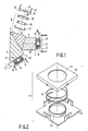
- a solid-state image sensor 6, 7, 8 is fixed to each exit window 3, 4, 5 by means of an associated holder 9, 10, 11.
- a solid-state image sensor (for example 6) generally comprises an envelope 40 containing an image-receiving surface 41 and to which connection pins 42 are secured for providing an output according to an image to be recorded.
- Each solid-state image sensor 6, 7, 8 is fixed to its corresponding exit window 3, 4, 5 in such a way that the image-receiving surfaces 41, 43, 44 are parallel to the exit windows.
- the individual parts of the holder 9 are separately shown in Figure 1.
- Each holder 9, 10, 11 comprises a first holder plate 12, 13, 14 having an aperture 45, 46, 47 and which is secured to the relevant exit window 3, 4, 5, and a second holder plate 15, 16, 17 having an aperture 48, 49, 50 and to which the associated solid-state image sensor 6, 7, 8 is fixed.
- An elastically deformable element 18, 19, 20 is provided between each first holder plate 12, 13, 14 and each second holder plate 15, 16, 17.
- the image sensor is brought into a desired position relative to the corresponding exit window by virtue of the cooperation of the elastically deformable element with the two holder plates of each holder. This desired position is fixed by securing the two holder plates to each other by means of a fixation element, for example an adhesive.
- FIG 2 is a diagrammatic view of an embodiment of a holder 51 for an optical assembly in accordance with the invention, in which an elastically deformable element 52 surrounds apertures 53 and 54 of holder plates 55 and 56.
- the elastically deformable element 52 is a spiral-shaped spring.
- the individual parts of the holder 51 are shown separately. Since the elastically deformable element 52 surrounds the apertures the holder plates 55 and 56 can be tilted relative to one another into any desired position in a simple and defined manner, as will be described hereinafter.
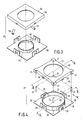
- Alternative embodiments of a holder for an optical assembly, in which the holder plates of the holder can be placed in any desired position relative to one another are shown in Figures 3 and 4.
- the elastically deformable element 52 comprises three separate segments 57, 58 and 59 which surround the apertures 53 and 54 of the holder plates 55 and 56.
- the separate segments 57, 58, 59 are rubber tubes.
- Figure 4 shows an alternative embodiment of a holder 21 for an optical assembly in accordance with the invention, in which the elastically deformable element comprises four cylindrical elements 22, 23, 24 and 25 which define the vertices of an imaginary rectangle 60 surrounding apertures 61, 62 of holder plates 26, 27.
- the individual parts of the holder 21 are shown separately.
- the holder 21 is formed by assembling the first holder plate 26 and the second holder plate 27 together the rubber elements 22, 23, 24, 25 being inserted between them.
- the holder plates 26 and 27 are loosely coupled together and are provided with respective cooperating stop surfaces 28 and 29 which, in the assembled condition, are urged against one another by the rubber elements as the diagrammatic, sectional view of Figure 5 shows.
- the spacing between the first holder plate 26 and the second holder plate 27 is substantially constant throughout the entire surface of the holder plates.
- the two holder plates 26, 27 can be tilted relative to one another, for example, by pressing the holder plates towards one another at the location of the rubber element 22, as is shown in the schematic front view of Figure 6.
- the distance between the holder plates can be varied from, for example, d1 , at the location of the rubber element 22, to d2, at the location of the rubber element 23. If the pressure is removed at the location of the rubber element 22, the rubber elements will again urge the holder plates to a position in which their stop surfaces abut.
- the first holder plate 26 and the second holder plate 27 are provided with projections 30 and apertures 31 respectively which locate opposite ends of the rubber elements.
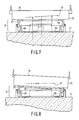
- the solid-state image sensor 70 is fixed to the second holder plate 27, for example, by means of an adhesive ( Figure 7).
- An image-receiving surface 72 of the solid-state image sensor 70 is accommodated in an envelope 73 of the image sensor 70 and it is assumed that its exact position relative to the envelope 73 is unknown.
- a test pattern is displayed on the entrance window of the colour-separation system, the test pattern being incident on the image-receiving surface 72 (see arrows in Figure 7) via the exit window 71 and passing through apertures 61, 62 of the holder 21.
- This test pattern is recorded by connecting the image sensor to a monitor (not shown in Figure 7).
- the image-receiving surface 72 can be oriented parallel to the exit window 71 by tilting the image sensor 70 until a desired test pattern is recorded.
- the two holder plates are rigidly secured to one another in this desired relative position.
- This can be carried out, for example, by means of an adhesive. Since an adhesive needs some time to cure the image sensor has to be held in the desired position during the curing time.
- a UV-curable adhesive is used so that the fixation can be carried out rapidly and in a defined manner.
- the image sensor is displaced over the exit window until a desired test pattern is displayed, after which the first holder plate 26 is secured to the exit window. If this displacement is not necessary the first holder plate 26 can be secured to the exit window at an earlier stage.
Abstract
Description
- The invention relates to an optical assembly for a camera, comprising a colour-separation system having an entrance window and at least one exit window, and a solid-state image sensor which is fixed opposite the or each exit window, and which comprises an image-receiving surface accommodated in an envelope.
- The invention also relates to a method of manufacturing such an optical assembly.
- The image-receiving surface of the solid-state image sensor of an optical assembly as mentioned in the opening paragraph is accommodated in an envelope and often the exact position of the image-receiving surface relative to the envelope is unknown. Consequently, also the position of the image-receiving surface relative to the exit window in question is not known.
- To obtain a properly functioning camera for television, film and photographic recordings, it is desirable for the image-receiving surface of the image sensor to be secured to the relevant exit window in this aligned position.
- It is an object of the invention to provide an optical assembly for a camera, which enables the image sensor to be previously secured to the relevant exit window in an aligned position, in a simple and accurate manner.
- To this end, an optical assembly of the type mentioned in the opening paragraph is characterized in accordance with the invention in that the solid-state image sensor is fixed to the exit window by means of a holder which comprises two holder plates having facing apertures and which are fixed to the exit window and the solid-state image sensor respectively, an elastically deformable element cooperating with and acting between the holder plates, the holder plates being secured in a desired position relative to one another by fixation means. The invention is based on the insight that due to the use of two holder plates and an elastically deformable element which form an integrated entity and, in addition, cooperate with each other so as to enable the two holder plates to be positioned relative to one another, the image sensor can be positioned relative to the exit window and supported during the positioning operation.
- From EP-A-0231382 it is known per se to secure a holder of iron or a similar material to both the image sensor and the relevant exit window, and solder both holders to one another in an aligned position. However, during the positioning of the holders described in the said Application they do not form an integrated entity which supports the image sensor, and cooperation between the holders, enabling them to be positioned relative to each other, is not suggested.
- A preferred embodiment of an optical assembly in accordance with the invention is characterized in that the elastically deformable element surrounds the apertures in the holder plates of the associated holder. Since the elastically deformable element surrounds the apertures, the holder plates can be tilted in any desired position relative to one another in a simple, defined manner, so that the image-receiving surface of the image sensor can be placed in any desired position relative to the relevant exit window. Alternative embodiments of an optical assembly in accordance with the invention are characterized in that the elastically deformable element comprises separate segments which at least partly surround the apertures in the holder plates of the associated holder, or in that the elastically deformable element comprises four separate segments which define the vertices of an imaginary rectangle which surrounds the apertures in the holder plates of the associated holder. A further preferred embodiment of an optical assembly in accordance with the invention is characterized in that the fixation means is a UV-light curable adhesive. If a UV-light curable adhesive is used, the two holder plates of the solid- state image sensor can be rapidly secured to one another in the desired position, such that during the fixation any variation in the adjusted position is minimal.
- A further preferred embodiment of an optical assembly in accordance with the invention is characterized in that the image-receiving surface of the solid-state image sensor is substantially parallel to the exit window. Consequently, the image-receiving surface of each solid-state image sensor is sufficiently accurately positioned relative to the relevant exit window, and a camera can optimally record an image to be picked up.
- A method of manufacturing an optical assembly having a colour separation system for a camera, in which, during a process step, a solid-state image sensor is fixed opposite an exit window in an aligned position, is characterized in accordance with the invention in that before the solid-state image sensor is fixed opposite the exit window, a holder is formed from a first and a second holder plate and an elastically deformable element provided between the holder plates, the holder plates being tiltable relative to one another by virtue of the elastically deformable element, the solid-state image sensor is fixed to the second holder plate, the holder with the solid-state image sensor is arranged over the exit window, a test pattern is imaged on the entrance window of the colour separation system, the first and the second holder plates are tilted relative to one another until the image sensor records a desired test pattern, and in that the two holder plates are secured to one another in an aligned position by means of a fixation element. On account of this, the solid-state image sensor can be rapidly and accurately fixed in a desired position opposite the relevant exit window.
- A few exemplary embodiments of an optical assembly in accordance with the invention will now be described with reference to the drawings, in which
- Figure 1 is a diagrammatic, sectional view of an optical assembly in accordance with the invention,
- Figure 2 is a diagrammatic, perspective view of an embodiment of a holder for an image sensor of an optical assembly in accordance with the invention,
- Figure 3 is a diagrammatic, perspective view of an alternative embodiment of a holder for an optical assembly in accordance with the invention,
- Figure 4 is a diagrammatic, perspective view of a further alternative embodiment of a holder for an optical assembly in accordance with the invention,
- Figure 5 is a diagrammatic, sectional view of the holder for an optical assembly, taken on the line V-V in Figure 4,
- Figure 6 is a diagrammatic side view of the holder for an optical assembly, viewed in the direction of the arrow VI shown in Figure 4, and
- Figures 7 and 8 are diagrammatic, sectional views of a solid-state image sensor fixed to an exit window.
- By way of example, the invention will be described by means of an optical assembly for a colour television camera having a
colour separation system 1 with oneentrance window 2 and threeexit windows state image sensor exit window holder envelope 40 containing an image-receiving surface 41 and to which connection pins 42 are secured for providing an output according to an image to be recorded. Each solid-state image sensor corresponding exit window receiving surfaces holder 9 are separately shown in Figure 1. Eachholder first holder plate aperture relevant exit window second holder plate aperture state image sensor deformable element first holder plate second holder plate - Figure 2 is a diagrammatic view of an embodiment of a
holder 51 for an optical assembly in accordance with the invention, in which an elasticallydeformable element 52surrounds apertures holder plates deformable element 52 is a spiral-shaped spring. For clarity, the individual parts of theholder 51 are shown separately. Since the elasticallydeformable element 52 surrounds the apertures theholder plates - In Figure 3, the elastically
deformable element 52 comprises threeseparate segments apertures holder plates separate segments - Figure 4 shows an alternative embodiment of a
holder 21 for an optical assembly in accordance with the invention, in which the elastically deformable element comprises fourcylindrical elements imaginary rectangle 60 surroundingapertures holder plates holder 21 are shown separately. - The function of the elastically deformable element of the holder will be explained by means of the method of manufacturing an optical assembly for a television camera in accordance with the invention, and will be described, by way of example, with reference to the Figures 4 up to and including 8. As is shown in Figure 4, the
holder 21 is formed by assembling thefirst holder plate 26 and thesecond holder plate 27 together therubber elements holder plates stop surfaces first holder plate 26 and thesecond holder plate 27 is substantially constant throughout the entire surface of the holder plates. - The two
holder plates rubber element 22, as is shown in the schematic front view of Figure 6. On account of the cooperation of therubber elements rubber element 22, to d₂, at the location of therubber element 23. If the pressure is removed at the location of therubber element 22, the rubber elements will again urge the holder plates to a position in which their stop surfaces abut. - Due to the fact that the rubber elements are elastically deformable it is clear that the holder plates can be tilted relative to one another in any desired position.
- In order to avoid a variation in the position of the rubber elements when pressure is applied, the
first holder plate 26 and thesecond holder plate 27 are provided withprojections 30 andapertures 31 respectively which locate opposite ends of the rubber elements. - The solid-
state image sensor 70 is fixed to thesecond holder plate 27, for example, by means of an adhesive (Figure 7). - An image-receiving
surface 72 of the solid-state image sensor 70 is accommodated in anenvelope 73 of theimage sensor 70 and it is assumed that its exact position relative to theenvelope 73 is unknown. - To place the solid-
state image sensor 70, or more precisely the image-receivingsurface 72, into a desired position relative to theexit window 71 opposite which the said image sensor is arranged, a test pattern is displayed on the entrance window of the colour-separation system, the test pattern being incident on the image-receiving surface 72 (see arrows in Figure 7) via theexit window 71 and passing throughapertures holder 21. This test pattern is recorded by connecting the image sensor to a monitor (not shown in Figure 7). As is schematically shown in Figure 8, the image-receiving surface 72 can be oriented parallel to theexit window 71 by tilting theimage sensor 70 until a desired test pattern is recorded. Subsequently, the two holder plates are rigidly secured to one another in this desired relative position. This can be carried out, for example, by means of an adhesive. Since an adhesive needs some time to cure the image sensor has to be held in the desired position during the curing time. Preferably, a UV-curable adhesive is used so that the fixation can be carried out rapidly and in a defined manner. - If in order to obtain a properly functioning camera it is additionally required that the central axis extending perpendicularly to the image-receiving surface coincides substantially with the optical axis of the relevant exit window, the image sensor is displaced over the exit window until a desired test pattern is displayed, after which the
first holder plate 26 is secured to the exit window. If this displacement is not necessary thefirst holder plate 26 can be secured to the exit window at an earlier stage.
Claims (7)
Applications Claiming Priority (2)
| Application Number | Priority Date | Filing Date | Title |
|---|---|---|---|
| NL8801291 | 1988-05-19 | ||
| NL8801291A NL8801291A (en) | 1988-05-19 | 1988-05-19 | OPTICAL COMPOSITION FOR A TELEVISION CAMERA INCLUDING AN IMAGE SENSOR AND METHOD FOR MANUFACTURING SUCH AN OPTICAL COMPOSITION. |
Publications (2)
| Publication Number | Publication Date |
|---|---|
| EP0342753A1 true EP0342753A1 (en) | 1989-11-23 |
| EP0342753B1 EP0342753B1 (en) | 1994-08-03 |
Family
ID=19852320
Family Applications (1)
| Application Number | Title | Priority Date | Filing Date |
|---|---|---|---|
| EP89201220A Expired - Lifetime EP0342753B1 (en) | 1988-05-19 | 1989-05-16 | Optical assembly for a camera having an image sensor |
Country Status (6)
| Country | Link |
|---|---|
| US (1) | US4933752A (en) |
| EP (1) | EP0342753B1 (en) |
| JP (1) | JP2765723B2 (en) |
| KR (1) | KR900018731A (en) |
| DE (1) | DE68917204T2 (en) |
| NL (1) | NL8801291A (en) |
Cited By (1)
| Publication number | Priority date | Publication date | Assignee | Title |
|---|---|---|---|---|
| US5134468A (en) * | 1989-02-21 | 1992-07-28 | Canon Kabushiki Kaisha | Optical apparatus for varying the lengths of optical path of color component light beams |
Families Citing this family (5)
| Publication number | Priority date | Publication date | Assignee | Title |
|---|---|---|---|---|
| US4890899A (en) * | 1987-05-18 | 1990-01-02 | Matsushita Electric Industrial Co., Ltd. | Color separation optical system which utilizes glass frit for bonding |
| US5510937A (en) * | 1992-12-14 | 1996-04-23 | Asahi Kogaku Kogyo Kabushiki Kaisha | Apparatus for adjusting intermeshing angle in feed screw mechanism |
| US6956610B1 (en) * | 1999-02-18 | 2005-10-18 | Linvatec Corporation | Shock mounting system for CCD camera |
| US7557860B2 (en) * | 2004-11-04 | 2009-07-07 | Linvatec Corporation | Elastomeric camera mounting system |
| JP2007166299A (en) * | 2005-12-14 | 2007-06-28 | Sony Corp | Solid-state imaging element, color decomposition imaging optical system, and imaging device |
Citations (3)
| Publication number | Priority date | Publication date | Assignee | Title |
|---|---|---|---|---|
| GB2078935A (en) * | 1980-05-16 | 1982-01-13 | Bell & Howell Co | Colour-separating optical system with positioned photodetector |
| GB2165092A (en) * | 1984-09-26 | 1986-04-03 | Rca Corp | Solid-state imager chip mounting |
| EP0231382A1 (en) * | 1985-06-17 | 1987-08-12 | Sony Corporation | Apparatus and method of adjusting registration of solid-state image pickup elements |
Family Cites Families (6)
| Publication number | Priority date | Publication date | Assignee | Title |
|---|---|---|---|---|
| JPS5842004A (en) * | 1981-09-07 | 1983-03-11 | Canon Inc | Positioning method for optical element |
| US4591901A (en) * | 1984-03-30 | 1986-05-27 | Rca Corporation | Television camera with solid-state imagers mounted to a prism |
| JPS6116690A (en) * | 1984-07-03 | 1986-01-24 | Olympus Optical Co Ltd | Image pickup device |
| US4789891A (en) * | 1985-09-11 | 1988-12-06 | Fuji Photo Optical Co., Ltd. | Spacer with an inclined surface for mounting a solid image pickup element to a color separation prism |
| US4835600A (en) * | 1986-07-21 | 1989-05-30 | Konishiroku Photo Industry Co., Ltd. | Solid state image reading device with sensors adhered to plate which is adhered to lens holding member |
| JPS63267087A (en) * | 1987-04-24 | 1988-11-04 | Matsushita Electric Ind Co Ltd | Color solid-state image pickup device |
-
1988
- 1988-05-19 NL NL8801291A patent/NL8801291A/en not_active Application Discontinuation
-
1989
- 1989-05-16 DE DE68917204T patent/DE68917204T2/en not_active Expired - Fee Related
- 1989-05-16 EP EP89201220A patent/EP0342753B1/en not_active Expired - Lifetime
- 1989-05-16 JP JP1120614A patent/JP2765723B2/en not_active Expired - Fee Related
- 1989-05-16 KR KR1019890006503A patent/KR900018731A/en not_active Application Discontinuation
- 1989-05-16 US US07/352,422 patent/US4933752A/en not_active Expired - Lifetime
Patent Citations (3)
| Publication number | Priority date | Publication date | Assignee | Title |
|---|---|---|---|---|
| GB2078935A (en) * | 1980-05-16 | 1982-01-13 | Bell & Howell Co | Colour-separating optical system with positioned photodetector |
| GB2165092A (en) * | 1984-09-26 | 1986-04-03 | Rca Corp | Solid-state imager chip mounting |
| EP0231382A1 (en) * | 1985-06-17 | 1987-08-12 | Sony Corporation | Apparatus and method of adjusting registration of solid-state image pickup elements |
Non-Patent Citations (1)
| Title |
|---|
| PATENT ABSTRACTS OF JAPAN, vol. 9, no. 110 (E-314)[1833], 15th May 1985, page 22 E 314; JP-A-60 166 (MITSUBISHI DENKI K.K.) 05-01-1985 * |
Cited By (1)
| Publication number | Priority date | Publication date | Assignee | Title |
|---|---|---|---|---|
| US5134468A (en) * | 1989-02-21 | 1992-07-28 | Canon Kabushiki Kaisha | Optical apparatus for varying the lengths of optical path of color component light beams |
Also Published As
| Publication number | Publication date |
|---|---|
| DE68917204T2 (en) | 1995-03-02 |
| EP0342753B1 (en) | 1994-08-03 |
| NL8801291A (en) | 1989-12-18 |
| KR900018731A (en) | 1990-12-22 |
| JP2765723B2 (en) | 1998-06-18 |
| JPH0222969A (en) | 1990-01-25 |
| US4933752A (en) | 1990-06-12 |
| DE68917204D1 (en) | 1994-09-08 |
Similar Documents
| Publication | Publication Date | Title |
|---|---|---|
| US4644632A (en) | Method of assembling the optical components of an optical apparatus and a device therefor | |
| US4591901A (en) | Television camera with solid-state imagers mounted to a prism | |
| US4268119A (en) | Color-separating optical system | |
| US7088397B1 (en) | Image sensor packaging with imaging optics | |
| EP0342753A1 (en) | Optical assembly for a camera having an image sensor | |
| US5708472A (en) | Optical image recording and reading apparatus | |
| JP2608048B2 (en) | Integrated imager-prism structure | |
| EP0424062A2 (en) | Process for assembling smaller scanning or printing arrays together to form a longer array | |
| EP0089724A1 (en) | Camera for pickung up coloured pictures | |
| JP2000354131A (en) | Focusing method in image pickup device | |
| AU4740385A (en) | Camera for recording television, photographic and cinematographic images, comprising an automatic focusing device | |
| EP2034721B1 (en) | System and method for positioning and fixing an image sensor to a beamsplitter | |
| US4531818A (en) | Adapter for arranging an instant picture cassette at a 35 mm camera and method for manufacturing the same | |
| DE3716352C2 (en) | ||
| DE3724127A1 (en) | IMAGE READER | |
| GB2178579A (en) | Fixation device for an electronic display | |
| JPH05100136A (en) | Image pickup device | |
| JP3467046B2 (en) | Optical device | |
| JPH05102448A (en) | Solid-state image sensor | |
| JPS6116690A (en) | Image pickup device | |
| US20100283891A1 (en) | Method of setting position of imaging device | |
| JP2850802B2 (en) | Back focus adjustment device for flying object mounted camera | |
| JPH0884217A (en) | Mounting structure for solid-state image pickup element in image reader | |
| JPH10150588A (en) | Method and unit for attaching solid-state image-pickup element | |
| JP3406808B2 (en) | Interchangeable camera back camera |
Legal Events
| Date | Code | Title | Description |
|---|---|---|---|
| PUAI | Public reference made under article 153(3) epc to a published international application that has entered the european phase |
Free format text: ORIGINAL CODE: 0009012 |
|
| AK | Designated contracting states |
Kind code of ref document: A1 Designated state(s): DE FR GB NL |
|
| 17P | Request for examination filed |
Effective date: 19900518 |
|
| 17Q | First examination report despatched |
Effective date: 19920413 |
|
| GRAA | (expected) grant |
Free format text: ORIGINAL CODE: 0009210 |
|
| AK | Designated contracting states |
Kind code of ref document: B1 Designated state(s): DE FR GB NL |
|
| PG25 | Lapsed in a contracting state [announced via postgrant information from national office to epo] |
Ref country code: NL Effective date: 19940803 |
|
| REF | Corresponds to: |
Ref document number: 68917204 Country of ref document: DE Date of ref document: 19940908 |
|
| ET | Fr: translation filed | ||
| NLV1 | Nl: lapsed or annulled due to failure to fulfill the requirements of art. 29p and 29m of the patents act | ||
| PLBE | No opposition filed within time limit |
Free format text: ORIGINAL CODE: 0009261 |
|
| STAA | Information on the status of an ep patent application or granted ep patent |
Free format text: STATUS: NO OPPOSITION FILED WITHIN TIME LIMIT |
|
| REG | Reference to a national code |
Ref country code: FR Ref legal event code: CD |
|
| 26N | No opposition filed | ||
| REG | Reference to a national code |
Ref country code: FR Ref legal event code: CD |
|
| REG | Reference to a national code |
Ref country code: GB Ref legal event code: IF02 |
|
| PGFP | Annual fee paid to national office [announced via postgrant information from national office to epo] |
Ref country code: FR Payment date: 20020527 Year of fee payment: 14 |
|
| PGFP | Annual fee paid to national office [announced via postgrant information from national office to epo] |
Ref country code: GB Payment date: 20020531 Year of fee payment: 14 |
|
| PGFP | Annual fee paid to national office [announced via postgrant information from national office to epo] |
Ref country code: DE Payment date: 20020719 Year of fee payment: 14 |
|
| PG25 | Lapsed in a contracting state [announced via postgrant information from national office to epo] |
Ref country code: GB Free format text: LAPSE BECAUSE OF NON-PAYMENT OF DUE FEES Effective date: 20030516 |
|
| PG25 | Lapsed in a contracting state [announced via postgrant information from national office to epo] |
Ref country code: DE Free format text: LAPSE BECAUSE OF NON-PAYMENT OF DUE FEES Effective date: 20031202 |
|
| GBPC | Gb: european patent ceased through non-payment of renewal fee |
Effective date: 20030516 |
|
| PG25 | Lapsed in a contracting state [announced via postgrant information from national office to epo] |
Ref country code: FR Free format text: LAPSE BECAUSE OF NON-PAYMENT OF DUE FEES Effective date: 20040130 |
|
| REG | Reference to a national code |
Ref country code: FR Ref legal event code: ST |