EP0342676A2 - Apparatus for localized heat and cold therapy - Google Patents
Apparatus for localized heat and cold therapy Download PDFInfo
- Publication number
- EP0342676A2 EP0342676A2 EP89108966A EP89108966A EP0342676A2 EP 0342676 A2 EP0342676 A2 EP 0342676A2 EP 89108966 A EP89108966 A EP 89108966A EP 89108966 A EP89108966 A EP 89108966A EP 0342676 A2 EP0342676 A2 EP 0342676A2
- Authority
- EP
- European Patent Office
- Prior art keywords
- hot
- cold
- pad
- temperature
- heat sink
- Prior art date
- Legal status (The legal status is an assumption and is not a legal conclusion. Google has not performed a legal analysis and makes no representation as to the accuracy of the status listed.)
- Withdrawn
Links
- 238000002560 therapeutic procedure Methods 0.000 title abstract description 22
- 239000004020 conductor Substances 0.000 claims abstract description 5
- 239000007788 liquid Substances 0.000 claims description 17
- 230000001225 therapeutic effect Effects 0.000 claims description 15
- 238000010438 heat treatment Methods 0.000 claims description 14
- 238000001816 cooling Methods 0.000 claims description 11
- 229920002994 synthetic fiber Polymers 0.000 claims description 2
- 239000002826 coolant Substances 0.000 claims 8
- 238000005086 pumping Methods 0.000 claims 2
- 238000000605 extraction Methods 0.000 claims 1
- 238000009827 uniform distribution Methods 0.000 claims 1
- XLYOFNOQVPJJNP-UHFFFAOYSA-N water Substances O XLYOFNOQVPJJNP-UHFFFAOYSA-N 0.000 abstract description 12
- RYGMFSIKBFXOCR-UHFFFAOYSA-N Copper Chemical group [Cu] RYGMFSIKBFXOCR-UHFFFAOYSA-N 0.000 abstract description 6
- 239000002184 metal Substances 0.000 abstract description 6
- 229910052751 metal Inorganic materials 0.000 abstract description 6
- 239000005060 rubber Substances 0.000 abstract description 4
- 239000002923 metal particle Substances 0.000 abstract description 2
- 238000007664 blowing Methods 0.000 abstract 1
- 239000012530 fluid Substances 0.000 description 22
- 239000000463 material Substances 0.000 description 6
- 229910052802 copper Inorganic materials 0.000 description 5
- 239000010949 copper Substances 0.000 description 5
- 238000010276 construction Methods 0.000 description 4
- 239000004033 plastic Substances 0.000 description 4
- 238000005057 refrigeration Methods 0.000 description 4
- 238000009833 condensation Methods 0.000 description 2
- 230000005494 condensation Effects 0.000 description 2
- 230000000694 effects Effects 0.000 description 2
- 230000001788 irregular Effects 0.000 description 2
- 229910052582 BN Inorganic materials 0.000 description 1
- PZNSFCLAULLKQX-UHFFFAOYSA-N Boron nitride Chemical compound N#B PZNSFCLAULLKQX-UHFFFAOYSA-N 0.000 description 1
- 230000004913 activation Effects 0.000 description 1
- 230000000712 assembly Effects 0.000 description 1
- 238000000429 assembly Methods 0.000 description 1
- 230000037237 body shape Effects 0.000 description 1
- 239000000919 ceramic Substances 0.000 description 1
- 239000003086 colorant Substances 0.000 description 1
- 230000003247 decreasing effect Effects 0.000 description 1
- 238000010586 diagram Methods 0.000 description 1
- 238000010292 electrical insulation Methods 0.000 description 1
- 238000001704 evaporation Methods 0.000 description 1
- 239000004744 fabric Substances 0.000 description 1
- 239000002657 fibrous material Substances 0.000 description 1
- 239000000499 gel Substances 0.000 description 1
- JEIPFZHSYJVQDO-UHFFFAOYSA-N iron(III) oxide Inorganic materials O=[Fe]O[Fe]=O JEIPFZHSYJVQDO-UHFFFAOYSA-N 0.000 description 1
- 239000004973 liquid crystal related substance Substances 0.000 description 1
- 238000012423 maintenance Methods 0.000 description 1
- 230000013011 mating Effects 0.000 description 1
- 238000012986 modification Methods 0.000 description 1
- 230000004048 modification Effects 0.000 description 1
- 239000003507 refrigerant Substances 0.000 description 1
- 239000000126 substance Substances 0.000 description 1
Images


Classifications
-
- A—HUMAN NECESSITIES
- A61—MEDICAL OR VETERINARY SCIENCE; HYGIENE
- A61F—FILTERS IMPLANTABLE INTO BLOOD VESSELS; PROSTHESES; DEVICES PROVIDING PATENCY TO, OR PREVENTING COLLAPSING OF, TUBULAR STRUCTURES OF THE BODY, e.g. STENTS; ORTHOPAEDIC, NURSING OR CONTRACEPTIVE DEVICES; FOMENTATION; TREATMENT OR PROTECTION OF EYES OR EARS; BANDAGES, DRESSINGS OR ABSORBENT PADS; FIRST-AID KITS
- A61F7/00—Heating or cooling appliances for medical or therapeutic treatment of the human body
- A61F7/0085—Devices for generating hot or cold treatment fluids
-
- A—HUMAN NECESSITIES
- A61—MEDICAL OR VETERINARY SCIENCE; HYGIENE
- A61F—FILTERS IMPLANTABLE INTO BLOOD VESSELS; PROSTHESES; DEVICES PROVIDING PATENCY TO, OR PREVENTING COLLAPSING OF, TUBULAR STRUCTURES OF THE BODY, e.g. STENTS; ORTHOPAEDIC, NURSING OR CONTRACEPTIVE DEVICES; FOMENTATION; TREATMENT OR PROTECTION OF EYES OR EARS; BANDAGES, DRESSINGS OR ABSORBENT PADS; FIRST-AID KITS
- A61F7/00—Heating or cooling appliances for medical or therapeutic treatment of the human body
-
- F—MECHANICAL ENGINEERING; LIGHTING; HEATING; WEAPONS; BLASTING
- F25—REFRIGERATION OR COOLING; COMBINED HEATING AND REFRIGERATION SYSTEMS; HEAT PUMP SYSTEMS; MANUFACTURE OR STORAGE OF ICE; LIQUEFACTION SOLIDIFICATION OF GASES
- F25B—REFRIGERATION MACHINES, PLANTS OR SYSTEMS; COMBINED HEATING AND REFRIGERATION SYSTEMS; HEAT PUMP SYSTEMS
- F25B21/00—Machines, plants or systems, using electric or magnetic effects
- F25B21/02—Machines, plants or systems, using electric or magnetic effects using Peltier effect; using Nernst-Ettinghausen effect
- F25B21/04—Machines, plants or systems, using electric or magnetic effects using Peltier effect; using Nernst-Ettinghausen effect reversible
-
- A—HUMAN NECESSITIES
- A61—MEDICAL OR VETERINARY SCIENCE; HYGIENE
- A61F—FILTERS IMPLANTABLE INTO BLOOD VESSELS; PROSTHESES; DEVICES PROVIDING PATENCY TO, OR PREVENTING COLLAPSING OF, TUBULAR STRUCTURES OF THE BODY, e.g. STENTS; ORTHOPAEDIC, NURSING OR CONTRACEPTIVE DEVICES; FOMENTATION; TREATMENT OR PROTECTION OF EYES OR EARS; BANDAGES, DRESSINGS OR ABSORBENT PADS; FIRST-AID KITS
- A61F7/00—Heating or cooling appliances for medical or therapeutic treatment of the human body
- A61F7/007—Heating or cooling appliances for medical or therapeutic treatment of the human body characterised by electric heating
- A61F2007/0075—Heating or cooling appliances for medical or therapeutic treatment of the human body characterised by electric heating using a Peltier element, e.g. near the spot to be heated or cooled
Definitions
- This invention relates to therapeutic devices and more particularly to an improved apparatus for localized heat and cold therapy.
- Electric blankets, heating pads, hot water bottles and ice bags are well known hot/cold localized therapy devices.
- the electric blankets and heating pads generally have electrical resistance elements incorporated in soft plastic or natural fiber material.
- Temperature select control switches are provided for controlling the amounts of electrical power applied to the elements. The switch selects power ranges and therefore temperature ranges of the blankets or pads.
- hot/cold therapy devices are used in hospitals; however, these devices are more sophisticated and costly.
- a hot/cold fluid is circulated through a flexible conduit in the pad to provide a preselected temperature output.
- the fluid temperature is maintained by three interdependent systems: a refrigeration/heating system, a temperature control system, and a fluid circulating system.
- the refrigeration/heating system has included a compressor, refrigerant condenser, and evaporating coils for cooling the fluid.
- heater elements are used where necessary for producing a hot fluid for circulation through the pad's flexible conduits.
- thermoelectric heat pump has been disclosed as a replacement for the refrigeration/heating system.
- the temperature control fluid circulating system utilizing the thermoelectric heat pump as the refrigeration/heating system includes a fluid tank having associated therewith at least one thermoelectric heat pump and a temperature sensor.
- a temperature controller is connected to the temperature sensor and to a power supply.
- the power supply is connected to the thermoelectric heat pump(s) and is responsive to the temperature control means for supplying power with the appropriate polarity to the thermoelectric heat pump to reach and maintain a selected fluid temperature.
- the fluid circulating system includes a pump to force the fluid from the tank through a flexible connecting pipe for circulation through the flexible conduit of the pad and return to the tank through a flexible return pipe.
- Another problem is water condensation. Water condensing on the flexible tube of the pad wets the pad; thus, a water proofed pad is required. Water condensing on the flexible interconnecting pipes can drip on the floor creating safety hazards to the patient and to those attending to the needs of a patient. Finally water condensing on the tank can drip into the tank housing to generate rust and electrical shorting problems.
- a disadvantage of the known refrigerator/heating system is the bulk of the system.
- the device is a portable device for movement from one hospital bed side to another, and once positioned occupies substantial bed side space, often in space competition with other required bed side devices.
- an object of the invention to provide an apparatus for localized hot/cold therapy having a substantially reduced mass to be heated/cooled for decreased apparatus cost and operating costs, and rapid heat up and cool down cycle times.
- Another object of the invention is to provide a hot/cold therapy apparatus which is substantially free of moisture condensation problems.
- a further object of the invention is to provide a hot/cold therapy apparatus of reduced bulk and weight for facilitating its portability.
- a further object of the invention is to provide a hot/cold therapy pad for direct application which does not utilize a circulating fluid to effect heat transfer.
- the localized heat/cold therapy apparatus constituting the subject matter of this invention consists of a system wherein the temperature is maintained by two interdependent subsystems: a heating/cooling subsystem, and a temperature control subsystem.
- the liquid support structure and circulating subsystems of known systems have been substantially eliminated.
- the hot/cold therapy device 10 constituting the subject matter of the invention includes a control box 12 having a control panel 14, a temperature sensor transducer 16, and a hot/cold thermal pad assembly 18.
- the control box 12 is umbilically connected to the thermal pad assembly 18 by an umbilical line (conduit) 20, hereinafter described.
- the control panel 14 includes a display 22.
- the display may be either a three digit liquid crystal or light emitting diode display for displaying temperature information.
- a display switch 23 is provided to display either the selected or actual pad temperature.
- a temperature status indicator 24 is provided for indicating the operational temperature status.
- the indicator includes a green light emitting diode for indicating operation as the selected temperature, and a pair of red light emitting diodes for indicating, respectively, temperatures above and below the selected operating temperature. If desired, different colors may be used to indicate temperatures above and below the desired operating temperature.
- a temperature selection dial 26 is provided for setting and adjusting the temperatures within cooling, warm, and hot temperature ranges.
- An ON/OFF switch 28 is provided for controlling the on/off operation of the device.
- the switch preferably may be either a press button or toggle type switch.
- An on indicator 30 completes the panel of the first embodiment, although it will be appreciated that maintenance indicators may be included for indicating failure of selected components.
- the on indicator 30 preferably is a light emitting diode.
- the hot/cold thermal pad assembly 18 is to provide uniformly heated or cooled areas which are typically larger than the cooling surface of the thermoelectric heat pump.
- the pad assembly includes a pad 32 of a size selected for use application.
- a thin plate 34 of conductive material can be attached to the pad 32 to extend the cooling area if necessary.
- a suitable conductive plate is a flexible copper plate having a thickness of about 2 mils. The conductive plate provides an attachment means for connecting the thermoelectric heat pump to the pad and also provides an extension of the hot/cold plate of a thermoelectric heat pump of a hot/cold assembly 36, hereinafter described.
- the hot/cold assembly 36 can be either permanently or removably attached to the pad.
- the pad is secured to the body using the known elastic, rubber or hook and eye loop straps, or provided with hook and loop pile type fastener material such as that sold under the trademark "VELCRO.”
- Velcro is a synthetic material which adheres when two pieces are pressed together.
- the temperature sensor is attached to the pad at any suitable location, and it is attached to engage the working media of the pad 32.
- the pad may be of several different types hereinafter described; each of the different types are bendable or shapable to closely conform to the contours and irregular body shapes to which it is applied.
- a pad cover 38 corresponding substantially to the shape of the pad encloses the bottom, sides, and all of the top except for the hot/cold assembly housing 40.
- the cover 38 includes a top portion 42 having an aperture through which the assembly housing 40 protrudes when the top of the pad cover is fastened to enclose the pad 32.
- a suitable fastener for securing the cover to the pad is preferably a hook, loop pile fastener, which includes patches 44 of VELCRO fixed to the pad's copper plate 34 and positioned to correspond to similar patches 46 fixed to the underneath side of the cover top 42.
- FIG. 1 discloses a preferred embodiment of the hot/cold assembly 36 of Figure 1.
- This preferred embodiment includes the housing 40 containing a thermoelectric heat pump 50 in modular form.
- the thermoelectric heat pump includes thermoelectric elements 52 having solderable ceramic plates for high electrical insulation and excellent thermal conductivity fixed, respectively, to the pad's conductive plate 34 and to a finned heat sink 54.
- a grill or louvered aperture 58 is formed in the housing 40 through which air at ambient temperature is either drawn or blown across the finned heat sink 54. If drawn the air flow is from the heat sink, through a conduit formed in the conduit 20, and out a grill 60 (Fig. 4) of the control box 12 by a fan 62 (Fig. 3a).
- the fan 62 is mounted in the control box 12.
- the umbilical line 20 also houses the electrical leads for the thermoelectric heat pump 50 and temperature sensor 16.
- Figure 2b discloses another embodiment of the hot/cold assembly 34. This embodiment is substantially that of Figure 2a except that the assembly housing 40 has an exit grill 64 formed in a side wall, and the fan 62 (including motor and fan blades) is mounted in the assembly housing 40 to draw air through grill 58, across the heat sink 56 and out the grill 64.
- the fan 62 including motor and fan blades
- Figure 2c discloses still another embodiment of the hot/cold assembly 34.
- the Figure 2c embodiment is substantially different from the preceding embodiments in that it includes a flexible heat pipe 66 having a cold/hot end connected to the pad's conductive plate 34 and a finned hot/cold end mounted in the control box 12 (Fig.4) adjacent the fan 62.
- the control box 12 further includes an air inlet grill 68.
- air is drawn through the inlet grill 68, across the finned hot/cold end of the heat pipe, and out the grill 60 by the fan 62 to maintain the finned hot/cold end substantially at ambient temperature.
- the heat pipe 66 can be constructed so that the fan 62 is eliminated but still result in substantially equivalent performance with the additional advantage of silent operation. By structuring a higher performance heat pipe and placing the finned end outside the control box 12 normal air movement is sufficient to maintain the finned hot/cold end substantially at ambient temperature.
- Figure 3a discloses circuitry for the hot/cold therapy device using the first embodiment of the hot/cold assembly 36.
- a source of power is connected to switch 28.
- Switch 28 is connected to the junction of the motor of fan 62, a power on indicating light emitting diode 30, and resistor of temperature selection potentiometer 70.
- the arm of potentiometer 70 is connected for adjustment by the temperature selection dial 26 for selecting the desired temperature setting, and to the junction of the positive terminal of a differential amplifier 72, an analog to digital converter (ADC) 76, and a window comparator 24 which may be, for example, a specialty integrated circuit manufactured by Burr Brown Incorporated.
- the ADC is connected to one side of a two way switch 78.
- the two way switch has its pole connected to a display driver 80 for driving the display 22.
- the temperature sensing transducer 16 has its output connected to an amplifier 82.
- Amplifier 82 amplifies the analog sensor signal to a working level.
- the amplifier 82 is connected to the junction of an analog to an ADC 84, window comparator 24, and to the negative terminal of the differential comparator 72.
- the ADC 84 is connected to the second side of the two way switch 78.
- the two way switch 78 is operable by a mechanical switch 23 with or without locking means to connect either the temperature setting digital signals or the actual temperature digital signals to the display driver 80 for display by the display 22.
- the differential comparator outputs a zero, positive, or negative voltage to the junction of the driver of the temperature status indicator 24 and to an amplifier 74.
- Amplifier 74 is connected to the thermoelectric heat pump 50 for driving the thermoelectric heat pump with a polarity for either heating or cooling the pad to the temperature setting.
- the circuitry (Fig. 3c) for the hot/cold device 10 using the second embodiment of the hot/cold assembly 36 (Fig. 2b) is identical to that of Figure 3a except that the fan 62 is located in the housing 40 of the hot/cold assembly 36. While, the circuitry for the heat pipe type hot/cold assembly 36 (Fig. 2c) is substantially that of the Figure 3a circuitry except that the heat pipe 66 replaces the fluid cooling system entirely.
- the device 10 includes a control box 12 with a control panel 14 formed thereon.
- the hot/cold therapy pad assembly 18 is connected by an umbilical line 20 to the control box 12.
- the control panel 14 includes a temperature display 22 having a press button switch 23 for selecting either the operating temperature of the pad 32 of the hot/cold therapy pad assembly or the temperature operation setting.
- a temperature status indicator 24 displays the operating temperature status during operation, and an operating temperature selection dial 26 is provided for setting the desired operation temperature.
- a fluid level warning indicator 100 which may be a light emitting diode, for example, is provided for indicating an unacceptable reservoir liquid level.
- a power ON/OFF switch 28 together with a power on indicator 30 completes the electrical portion of the panel 14.
- Liquid connectors 102 and 104 are mounted in the housing 14.
- Connector 102 is connected by a conduit 106 is a closed reservoir 108 for returning liquid from the therapy pad assembly 36.
- the reservoir has a filling aperture for filling the reservoir with a liquid such as water for a purpose hereinafter described.
- the reservoir 108 is equipped with either an electro/mechanical water level gauge 112 (Fig.3b) connected to the fluid level warning indicator 100 (Fig. 4) or an electronic liquid level sensor for indicating when the fluid level is unacceptably low.
- the connector 104 is connected by a conduit 14 to the outlet of a motor driven pump 116 having its inlet connected to the outlet of a radiator 118.
- the pump 116 and radiator 118 are shown in phantom to indicate their absence in the first embodiment.
- the radiator 118 has its inlet connected to the reservoir for receiving the liquid.
- a fan 62 is positioned with respect to the radiator 118 to blow air at ambient through the radiator. Grills 60 and 68 are provided in the housing 12 to accommodate air flow into and out of the housing.
- the umbilical line 20 includes flexible liquid conduits 120 and 122, and electrical leads 124 and 126 for the thermoelectric heat pump 50 and lead 128 for the temperature sensor 16 output; the conduits and leads are mounted in a flexible sleeve 130.
- the conduits have ends equipped with mating connectors for connection to the in and out connectors 102 and 104 of the housing 12.
- the hot/cold therapy pad assembly 36 is substantially that disclosed in Figure 2a, the only difference is that the finned heat sink 56 has been replaced by a block 132 of conductive material such as copper.
- the block has walls forming a passage 134 with bosses (Fig. 4) to which are fixed the flexible connectors 120 and 122 of the umbilical line.
- the electrical leads 124 and 126 are connected to the thermoelectric heat pump elements, and the electrical lead 128 is connected to the temperature sensor.
- the electrical circuit for the second embodiment is shown in Figure 3b, which is substantially that of Figure 3a modified to include power for the liquid pump 116 and the fluid level indicator 100 when the electro/mechanical switch 112 is closed.
- the source of power is connected to the ON/OFF switch 28.
- the On/Off switch 28 is connected to the junction of switch on indicator 30, temperature selector potentiometer 70, motors of centrifugal pump 116 and fan 62, and to a thermal of the switch of the electro/mechanical gauge 112.
- the pickoff arm of the potentiometer is activated mechanically by the temperature setting dial 26, and a voltage indicative of the temperature selection is connected to the junction of an ADC 76 and the positive terminal of differential amplifier 72.
- the ADC 76 is connected to the first side of a two way switch 78.
- the temperature sensor 16 is connected to an amplifier 82 to amplify the sensor voltage to a working level.
- the amplified output of amplifier 82 is connected to the junction of ADC 84 and the negative terminal of the differential comparator 72.
- the ADC 84 is connected to the second side of the switch 78.
- the pole of switch 78 is connected to a display driver 80 and the display driver is connected to the temperature display 22.
- the switch 78 is normally in contact with the second side of switch 78 to input digital signals of the sensor's ADC representative of the hot/cold pad temperature through the display driver to the display for display, and is spring loaded so that when pressed to contact the first side the temperature setting digital signals of the ADC pass through the display driver to the LED display for display.
- the positive, negative, or zero voltage output of the differential amplifier 72 is connected to the junction of the temperature status indicator 24 and an amplifier 74.
- the amplifier 74 amplifies the output of the differential comparator to provide a signal of the proper polarity to the terminals of the thermoelectric heat pump for selectively cooling or heating the plate in contact with the heating pad.
- the liquid in the heat sink block acts as a carrier for either supplying energy or removing energy to maintain the temperature of the heat sink at a working level.
- the purpose of the heat transfer pad is to provide uniformly heated or cooled area(s) which are typically larger than the cooling surface of the thermoelectric module. Further the heat transfer pad or wrap may be characterized as being bendable or shapable to closely conform to the contours and irregular shapes as on a patient's or animal's body parts or limbs.
- the first type of pad 32 (Fig. 5a) is a convective pad which includes the pad 130 in good thermal contact with the plate 52 of the thermoelectric heat pump 50.
- a gel, liquid, or other heat transfer substance 132 is contained in the pad 130 in either direct or indirect contact with the thermal module plate 52.
- a suitable gel is that sold under the trademark HYPOL by W. R. Grace Company.
- the pad 32 is a conductive pad which includes the pad 130 filled with layers 134 of thermally conductive flexible single, laminated, or braided sheets of metal, plastic, rubber, fabric or the like material in direct contact one to another, and with the top layer in direct contact with the cold plate 52 or the flexible copper plate 34 or both.
- the layers of the material are each about two mils thick and five layers are preferred. Thus, the total thickness of the layers is about ten mils.
- the pad 130 is filled with plastic layers 136 impregnated with metal particles. Again five layers each having a two mil thickness are preferred, although a ten mil thick block of the metal impregnated plastic material can be used with satisfactory results.
- the pad 130 can be filled with a thermally conductive gel, liquid, fluid or the like and a thermally conductive flexible structure 133 shown in phantom in Figure 5a of material immersed or embedded therein.
- the preferred pad 32 is a laminated structure of highly conductive thin metal (copper) sheets coated with a soft pliable thermally conductive boron nitride filled rubber. Such a material is that sold under the trademark CHOTHERM by Chomerics Incorporated.
- the laminated structure is preferred to provide sufficient pad crosssectional area for uniform heat transfer while maintaining bendability and flexibility in the overall structure.
- the cover 38 for the pad 32 may be a disposable cover. Also the pad 130 when removably attached to the laminated metal structure embodiments may be disposable.
- the device 10 In operation of the hot/cold therapy device 10 (Fig. 1), the device 10 is connected to a standard 120V, 60 Hz ac power supply or to a dc power supply.
- the power ON/OFF switch 28 is pressed to the on position, which position is indicated by the activation of the switch status indicator 28.
- the desired temperature is set by turning the temperature select/adjust dial 24 to the desired temperature setting, pressing the temperature display selection switch 23, and observing the temperature setting displayed on the display 22.
- the pad assembly 18 is attached to the patient.
- the temperature status monitor then indicates whether the temperature of the pad is at or above or below the set temperature, and the display 22 displays the pad's actual temperature.
- the system instantaneously directs an increase or decrease in power to the thermoelectric module for a temperature correction.
- the pad after about a two minute lead time, reaches the set temperature.
- the set temperature can be adjusted using the temperature control/adjust dial 26 for fine tuning the desired temperature setting.
Landscapes
- Health & Medical Sciences (AREA)
- Engineering & Computer Science (AREA)
- Life Sciences & Earth Sciences (AREA)
- Biomedical Technology (AREA)
- Heart & Thoracic Surgery (AREA)
- Vascular Medicine (AREA)
- Animal Behavior & Ethology (AREA)
- General Health & Medical Sciences (AREA)
- Public Health (AREA)
- Veterinary Medicine (AREA)
- Thermal Sciences (AREA)
- General Engineering & Computer Science (AREA)
- Mechanical Engineering (AREA)
- Physics & Mathematics (AREA)
- Thermotherapy And Cooling Therapy Devices (AREA)
Abstract
Description
- This invention relates to therapeutic devices and more particularly to an improved apparatus for localized heat and cold therapy.
- Electric blankets, heating pads, hot water bottles and ice bags are well known hot/cold localized therapy devices. The electric blankets and heating pads generally have electrical resistance elements incorporated in soft plastic or natural fiber material. Temperature select control switches are provided for controlling the amounts of electrical power applied to the elements. The switch selects power ranges and therefore temperature ranges of the blankets or pads.
- Similarly hot/cold therapy devices are used in hospitals; however, these devices are more sophisticated and costly. In these medically approved devices, a hot/cold fluid is circulated through a flexible conduit in the pad to provide a preselected temperature output. The fluid temperature is maintained by three interdependent systems: a refrigeration/heating system, a temperature control system, and a fluid circulating system. The refrigeration/heating system has included a compressor, refrigerant condenser, and evaporating coils for cooling the fluid. Again, heater elements are used where necessary for producing a hot fluid for circulation through the pad's flexible conduits.
- More recently, a thermoelectric heat pump has been disclosed as a replacement for the refrigeration/heating system. The temperature control fluid circulating system utilizing the thermoelectric heat pump as the refrigeration/heating system includes a fluid tank having associated therewith at least one thermoelectric heat pump and a temperature sensor. A temperature controller is connected to the temperature sensor and to a power supply. The power supply is connected to the thermoelectric heat pump(s) and is responsive to the temperature control means for supplying power with the appropriate polarity to the thermoelectric heat pump to reach and maintain a selected fluid temperature.
- The fluid circulating system includes a pump to force the fluid from the tank through a flexible connecting pipe for circulation through the flexible conduit of the pad and return to the tank through a flexible return pipe.
- It is recognized that problems attend the use of a fluid circulation system. One problem is the increased mass which has to be cooled. The mass includes the fluid holding tank, flexible connecting pipes, pad flexible tube, and pad. Thus, to heat the pad to a preselected temperature requires a larger thermoelectric heat pump and more power and time than would be required if only the pad were to be heated.
- Another problem is water condensation. Water condensing on the flexible tube of the pad wets the pad; thus, a water proofed pad is required. Water condensing on the flexible interconnecting pipes can drip on the floor creating safety hazards to the patient and to those attending to the needs of a patient. Finally water condensing on the tank can drip into the tank housing to generate rust and electrical shorting problems.
- A disadvantage of the known refrigerator/heating system is the bulk of the system. The device is a portable device for movement from one hospital bed side to another, and once positioned occupies substantial bed side space, often in space competition with other required bed side devices.
- Another disadvantage of the refrigerator/heating system is the attention required to maintain its proper operation. For example, the fluid tank must be filled and the fluid level maintained for proper operation. Further, the unit must be leveled after each moving for proper operation. Such units generally shut down automatically when tilted more than about eleven degrees. Failure to provide the required attention can result in equipment damage, operation failure, and the creation of safety hazards.
- Accordingly it is an object of the invention to provide an apparatus for localized hot/cold therapy having a substantially reduced mass to be heated/cooled for decreased apparatus cost and operating costs, and rapid heat up and cool down cycle times.
- Another object of the invention is to provide a hot/cold therapy apparatus which is substantially free of moisture condensation problems.
- A further object of the invention is to provide a hot/cold therapy apparatus of reduced bulk and weight for facilitating its portability.
- A further object of the invention is to provide a hot/cold therapy pad for direct application which does not utilize a circulating fluid to effect heat transfer.
- Briefly stated the localized heat/cold therapy apparatus constituting the subject matter of this invention consists of a system wherein the temperature is maintained by two interdependent subsystems: a heating/cooling subsystem, and a temperature control subsystem. The liquid support structure and circulating subsystems of known systems have been substantially eliminated.
- Other objects and features of the invention will become more readily understood from the following detailed description when read in conjunction with the drawings in which:
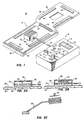
- Figure 1 is an isometric view of the hot/cold therapy device constituting the subject matter of the invention;
- Figures 2a - 2c are partial views of air cooled thermal pad assemblies of the hot/cold therapy device constituting the subject matter of the invention, the views are enlarged to show the details of construction;
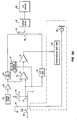
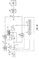
- Figures 3a - 3c are circuit diagrams of the control unit electronics for the various embodiments of the invention;
- Figure 4 is an isometric view of the control unit with a portion of the housing broken away to show interior details; and
- Figures 5a -5c are sectional views of pad constructions of the hot/cold therapy device constituting the subject matter of the invention.
- Referring now to Figure 1, the hot/
cold therapy device 10 constituting the subject matter of the invention includes acontrol box 12 having acontrol panel 14, atemperature sensor transducer 16, and a hot/coldthermal pad assembly 18. Thecontrol box 12 is umbilically connected to thethermal pad assembly 18 by an umbilical line (conduit) 20, hereinafter described. - In a first embodiment, the
control panel 14 includes adisplay 22. The display may be either a three digit liquid crystal or light emitting diode display for displaying temperature information. Adisplay switch 23 is provided to display either the selected or actual pad temperature. Atemperature status indicator 24 is provided for indicating the operational temperature status. The indicator includes a green light emitting diode for indicating operation as the selected temperature, and a pair of red light emitting diodes for indicating, respectively, temperatures above and below the selected operating temperature. If desired, different colors may be used to indicate temperatures above and below the desired operating temperature. Atemperature selection dial 26 is provided for setting and adjusting the temperatures within cooling, warm, and hot temperature ranges. An ON/OFF switch 28 is provided for controlling the on/off operation of the device. The switch preferably may be either a press button or toggle type switch. An onindicator 30 completes the panel of the first embodiment, although it will be appreciated that maintenance indicators may be included for indicating failure of selected components. The onindicator 30 preferably is a light emitting diode. - The hot/cold
thermal pad assembly 18 is to provide uniformly heated or cooled areas which are typically larger than the cooling surface of the thermoelectric heat pump. Thus, the pad assembly includes apad 32 of a size selected for use application. Athin plate 34 of conductive material can be attached to thepad 32 to extend the cooling area if necessary. A suitable conductive plate is a flexible copper plate having a thickness of about 2 mils. The conductive plate provides an attachment means for connecting the thermoelectric heat pump to the pad and also provides an extension of the hot/cold plate of a thermoelectric heat pump of a hot/cold assembly 36, hereinafter described. - The hot/
cold assembly 36 can be either permanently or removably attached to the pad. The pad is secured to the body using the known elastic, rubber or hook and eye loop straps, or provided with hook and loop pile type fastener material such as that sold under the trademark "VELCRO." Velcro is a synthetic material which adheres when two pieces are pressed together. The temperature sensor is attached to the pad at any suitable location, and it is attached to engage the working media of thepad 32. The pad may be of several different types hereinafter described; each of the different types are bendable or shapable to closely conform to the contours and irregular body shapes to which it is applied. - A
pad cover 38 corresponding substantially to the shape of the pad encloses the bottom, sides, and all of the top except for the hot/cold assembly housing 40. Thecover 38 includes atop portion 42 having an aperture through which theassembly housing 40 protrudes when the top of the pad cover is fastened to enclose thepad 32. A suitable fastener for securing the cover to the pad is preferably a hook, loop pile fastener, which includespatches 44 of VELCRO fixed to the pad'scopper plate 34 and positioned to correspond tosimilar patches 46 fixed to the underneath side of thecover top 42. - Referring now to Figures 2a -2c, Figure 2a discloses a preferred embodiment of the hot/
cold assembly 36 of Figure 1. This preferred embodiment includes thehousing 40 containing athermoelectric heat pump 50 in modular form. The thermoelectric heat pump includesthermoelectric elements 52 having solderable ceramic plates for high electrical insulation and excellent thermal conductivity fixed, respectively, to the pad'sconductive plate 34 and to afinned heat sink 54. A grill orlouvered aperture 58 is formed in thehousing 40 through which air at ambient temperature is either drawn or blown across thefinned heat sink 54. If drawn the air flow is from the heat sink, through a conduit formed in theconduit 20, and out a grill 60 (Fig. 4) of thecontrol box 12 by a fan 62 (Fig. 3a). Thefan 62 is mounted in thecontrol box 12. Theumbilical line 20 also houses the electrical leads for thethermoelectric heat pump 50 andtemperature sensor 16. - Figure 2b discloses another embodiment of the hot/
cold assembly 34. This embodiment is substantially that of Figure 2a except that theassembly housing 40 has anexit grill 64 formed in a side wall, and the fan 62 (including motor and fan blades) is mounted in theassembly housing 40 to draw air throughgrill 58, across the heat sink 56 and out thegrill 64. - Figure 2c discloses still another embodiment of the hot/
cold assembly 34. The Figure 2c embodiment is substantially different from the preceding embodiments in that it includes aflexible heat pipe 66 having a cold/hot end connected to the pad'sconductive plate 34 and a finned hot/cold end mounted in the control box 12 (Fig.4) adjacent thefan 62. Thecontrol box 12 further includes anair inlet grill 68. Thus, air is drawn through theinlet grill 68, across the finned hot/cold end of the heat pipe, and out thegrill 60 by thefan 62 to maintain the finned hot/cold end substantially at ambient temperature. Alternatively, theheat pipe 66 can be constructed so that thefan 62 is eliminated but still result in substantially equivalent performance with the additional advantage of silent operation. By structuring a higher performance heat pipe and placing the finned end outside thecontrol box 12 normal air movement is sufficient to maintain the finned hot/cold end substantially at ambient temperature. - Referring now to Figures 3a - 3c, Figure 3a discloses circuitry for the hot/cold therapy device using the first embodiment of the hot/
cold assembly 36. A source of power is connected to switch 28.Switch 28 is connected to the junction of the motor offan 62, a power on indicatinglight emitting diode 30, and resistor oftemperature selection potentiometer 70. The arm ofpotentiometer 70 is connected for adjustment by thetemperature selection dial 26 for selecting the desired temperature setting, and to the junction of the positive terminal of adifferential amplifier 72, an analog to digital converter (ADC) 76, and awindow comparator 24 which may be, for example, a specialty integrated circuit manufactured by Burr Brown Incorporated. The ADC is connected to one side of a twoway switch 78. The two way switch has its pole connected to adisplay driver 80 for driving thedisplay 22. Thetemperature sensing transducer 16 has its output connected to anamplifier 82.Amplifier 82 amplifies the analog sensor signal to a working level. Theamplifier 82 is connected to the junction of an analog to anADC 84,window comparator 24, and to the negative terminal of thedifferential comparator 72. TheADC 84 is connected to the second side of the twoway switch 78. The twoway switch 78 is operable by amechanical switch 23 with or without locking means to connect either the temperature setting digital signals or the actual temperature digital signals to thedisplay driver 80 for display by thedisplay 22. The differential comparator outputs a zero, positive, or negative voltage to the junction of the driver of thetemperature status indicator 24 and to anamplifier 74.Amplifier 74 is connected to thethermoelectric heat pump 50 for driving the thermoelectric heat pump with a polarity for either heating or cooling the pad to the temperature setting. - The circuitry (Fig. 3c) for the hot/
cold device 10 using the second embodiment of the hot/cold assembly 36 (Fig. 2b) is identical to that of Figure 3a except that thefan 62 is located in thehousing 40 of the hot/cold assembly 36. While, the circuitry for the heat pipe type hot/cold assembly 36 (Fig. 2c) is substantially that of the Figure 3a circuitry except that theheat pipe 66 replaces the fluid cooling system entirely. - Referring now to Figure 4, a second embodiment of the hot/cold therapy apparatus is shown with like numbers used to reference parts common to the parts of the first embodiment's structure. Thus, the
device 10 includes acontrol box 12 with acontrol panel 14 formed thereon. Atemperature sensor 16 and athermal pad assembly 18. The hot/coldtherapy pad assembly 18 is connected by anumbilical line 20 to thecontrol box 12. - The
control panel 14 includes atemperature display 22 having apress button switch 23 for selecting either the operating temperature of thepad 32 of the hot/cold therapy pad assembly or the temperature operation setting. Atemperature status indicator 24 displays the operating temperature status during operation, and an operatingtemperature selection dial 26 is provided for setting the desired operation temperature. A fluidlevel warning indicator 100, which may be a light emitting diode, for example, is provided for indicating an unacceptable reservoir liquid level. A power ON/OFF switch 28 together with a power onindicator 30 completes the electrical portion of thepanel 14.Liquid connectors housing 14. -
Connector 102 is connected by aconduit 106 is aclosed reservoir 108 for returning liquid from thetherapy pad assembly 36. The reservoir has a filling aperture for filling the reservoir with a liquid such as water for a purpose hereinafter described. Thereservoir 108 is equipped with either an electro/mechanical water level gauge 112 (Fig.3b) connected to the fluid level warning indicator 100 (Fig. 4) or an electronic liquid level sensor for indicating when the fluid level is unacceptably low. Theconnector 104 is connected by aconduit 14 to the outlet of a motor drivenpump 116 having its inlet connected to the outlet of aradiator 118. Thepump 116 andradiator 118 are shown in phantom to indicate their absence in the first embodiment. Theradiator 118 has its inlet connected to the reservoir for receiving the liquid. Afan 62 is positioned with respect to theradiator 118 to blow air at ambient through the radiator.Grills housing 12 to accommodate air flow into and out of the housing. - The
umbilical line 20 includes flexibleliquid conduits electrical leads thermoelectric heat pump 50 and lead 128 for thetemperature sensor 16 output; the conduits and leads are mounted in aflexible sleeve 130. The conduits have ends equipped with mating connectors for connection to the in and outconnectors housing 12. - The hot/cold
therapy pad assembly 36, is substantially that disclosed in Figure 2a, the only difference is that the finned heat sink 56 has been replaced by ablock 132 of conductive material such as copper. The block has walls forming apassage 134 with bosses (Fig. 4) to which are fixed theflexible connectors electrical lead 128 is connected to the temperature sensor. - The electrical circuit for the second embodiment is shown in Figure 3b, which is substantially that of Figure 3a modified to include power for the
liquid pump 116 and thefluid level indicator 100 when the electro/mechanical switch 112 is closed. It will be appreciated by one skilled in the art that an electronic switch can be used in place of the electro-mechanical switch. Thus, the source of power is connected to the ON/OFF switch 28. The On/Off switch 28 is connected to the junction of switch onindicator 30,temperature selector potentiometer 70, motors ofcentrifugal pump 116 andfan 62, and to a thermal of the switch of the electro/mechanical gauge 112. When the ON/OFF switch is closed power flows: to turn on thepower status indicator 30, to the resistor of the potentiometer, to run the motor of thecentrifugal pump 116, to run the fan motor of the fan, and when the electro/mechanical switch 112 is closed owing to a low water level, to turn on the fluid level warning indicator. - The pickoff arm of the potentiometer is activated mechanically by the
temperature setting dial 26, and a voltage indicative of the temperature selection is connected to the junction of anADC 76 and the positive terminal ofdifferential amplifier 72. TheADC 76 is connected to the first side of a twoway switch 78. Thetemperature sensor 16 is connected to anamplifier 82 to amplify the sensor voltage to a working level. The amplified output ofamplifier 82 is connected to the junction ofADC 84 and the negative terminal of thedifferential comparator 72. TheADC 84 is connected to the second side of theswitch 78. The pole ofswitch 78 is connected to adisplay driver 80 and the display driver is connected to thetemperature display 22. Theswitch 78 is normally in contact with the second side ofswitch 78 to input digital signals of the sensor's ADC representative of the hot/cold pad temperature through the display driver to the display for display, and is spring loaded so that when pressed to contact the first side the temperature setting digital signals of the ADC pass through the display driver to the LED display for display. - The positive, negative, or zero voltage output of the
differential amplifier 72 is connected to the junction of thetemperature status indicator 24 and anamplifier 74. Theamplifier 74 amplifies the output of the differential comparator to provide a signal of the proper polarity to the terminals of the thermoelectric heat pump for selectively cooling or heating the plate in contact with the heating pad. The liquid in the heat sink block acts as a carrier for either supplying energy or removing energy to maintain the temperature of the heat sink at a working level. - Referring now to Figures 5a - 5c for descriptions of
preferred pad 32 constructions for the above described embodiments. The purpose of the heat transfer pad is to provide uniformly heated or cooled area(s) which are typically larger than the cooling surface of the thermoelectric module. Further the heat transfer pad or wrap may be characterized as being bendable or shapable to closely conform to the contours and irregular shapes as on a patient's or animal's body parts or limbs. - Two basic types and a combination thereof are envisioned for "spreading" the heating or cooling effect throughout the pad. The first type of pad 32 (Fig. 5a) is a convective pad which includes the
pad 130 in good thermal contact with theplate 52 of thethermoelectric heat pump 50. A gel, liquid, or otherheat transfer substance 132 is contained in thepad 130 in either direct or indirect contact with thethermal module plate 52. A suitable gel is that sold under the trademark HYPOL by W. R. Grace Company. - In a second embodiment (Fig. 5b), the
pad 32 is a conductive pad which includes thepad 130 filled withlayers 134 of thermally conductive flexible single, laminated, or braided sheets of metal, plastic, rubber, fabric or the like material in direct contact one to another, and with the top layer in direct contact with thecold plate 52 or theflexible copper plate 34 or both. The layers of the material are each about two mils thick and five layers are preferred. Thus, the total thickness of the layers is about ten mils. - In a third embodiment (Fig. 5c), the
pad 130 is filled withplastic layers 136 impregnated with metal particles. Again five layers each having a two mil thickness are preferred, although a ten mil thick block of the metal impregnated plastic material can be used with satisfactory results. - It will be appreciated by those skilled in the art that the convention and conduction types can be combined to form a fourth embodiment. Thus, the
pad 130 can be filled with a thermally conductive gel, liquid, fluid or the like and a thermally conductiveflexible structure 133 shown in phantom in Figure 5a of material immersed or embedded therein. - The
preferred pad 32 is a laminated structure of highly conductive thin metal (copper) sheets coated with a soft pliable thermally conductive boron nitride filled rubber. Such a material is that sold under the trademark CHOTHERM by Chomerics Incorporated. The laminated structure is preferred to provide sufficient pad crosssectional area for uniform heat transfer while maintaining bendability and flexibility in the overall structure. Thecover 38 for thepad 32 may be a disposable cover. Also thepad 130 when removably attached to the laminated metal structure embodiments may be disposable. - In operation of the hot/cold therapy device 10 (Fig. 1), the
device 10 is connected to a standard 120V, 60 Hz ac power supply or to a dc power supply. The power ON/OFF switch 28 is pressed to the on position, which position is indicated by the activation of theswitch status indicator 28. The desired temperature is set by turning the temperature select/adjustdial 24 to the desired temperature setting, pressing the temperaturedisplay selection switch 23, and observing the temperature setting displayed on thedisplay 22. Thepad assembly 18 is attached to the patient. The temperature status monitor then indicates whether the temperature of the pad is at or above or below the set temperature, and thedisplay 22 displays the pad's actual temperature. The system instantaneously directs an increase or decrease in power to the thermoelectric module for a temperature correction. The pad, after about a two minute lead time, reaches the set temperature. The set temperature can be adjusted using the temperature control/adjustdial 26 for fine tuning the desired temperature setting. - Although several embodiments of the invention have been described, it will be apparent to a person skilled in the art that various modifications to details of construction shown and described may be made without departing from the scope of this invention.
Claims (10)
a therapeutic pad 32;
a hot/cold producing means 50 mounted on the pad, said means having first and second opposing sides with the first side in thermal contact with the pad;
means 54 in operative association with the second side of the hot/cold producing means for maintaining a working temperature difference at the second opposing end of the hot/cold producing means;
a temperature sensing means 16 connected to the therapeutic thermal pad for sensing the pad's temperature;
a conduit means 20 including electrical leads 124, 126, and 128 connected to the hot/cold producing means and temperature sensing means; and
a control means 12 and 14 connected to the electrical leads for controlling operation of the temperature controlled hot/cold therapeutic pad;
characterized in that the hot/cold producing means having first and second opposing sides includes a thermoelectric heat pump 50, and wherein the means in operative association with the second side of the opposing sides for maintaining a working temperature difference at the second opposing side includes a liquid cooled heat sink in thermal contact with the second hot/cold plate, said liquid cooled heat sink including a block 132 of thermal conductive material having walls forming a passage 134 for flowing liquid through the block for maintaining the operative temperature difference, the conduit means including first and second flexible conduits 120, 122 connected to the passage, and the control means includes a reservoir 108 connected to the first flexible conduit for receiving and storing a liquid coolant, a radiator 118 connected to the reservior a pump 116 connected to the reservior and to the second conduit means for pumping the liquid coolant from the reservoir through the radiator for heat extraction, second conduit, heat sink passage and return through the first conduit to the reservoir.
a thermoelectric heat pump element 52 sandwiched between first and second hot/cold plates, a hot/cold thermal pad means including a pad 32 operatively connected to the first hot/cold plate, means including a heat sink 54 connected to the second hot/cold plate for maintaining a temperature difference between the second hot/cold plate and heat sink, a temperature sensing means 16 connected to the pad for sensing the pad's temperature, and a control means 12, 14 connected remotely to the thermoelectric heat pump, temperature sensing means and means for maintaining a temperature difference between the second hot/cold plate and heat sink for controlling operation of the temperature controlled hot/cold thermal pad; and
characterized by said pad having a thermally conductive plate means 34 for forming an extension of the first hot/cold plate of the thermoelectric heat pump for substantially uniform distribution of the hot/cold plate output to the pad, further characterized in that the heat sink 54 of the means including a heat sink connected to the second hot/cold plate is a block 132 of thermal conductive material having walls forming a passage for a coolant for maintaining a temperature difference between the heat sink and second hot/cold plate, first and second conduits 120, 122 connected, respectively, to first and second ends of the passage, a reservior 108 mounted in the control means for containing the coolant, and means 116 for circulating the coolant through the first conduit, and passage and return of the coolant through the second conduit 122 to the reservior.
a hot/cold pad assembly means 34, for connection to a temperature control assembly, and a temperature control assembly means 12, 14 adapted for carriage by a portable supporting structure for controlling operation of the therapeutic apparatus, characterized by a conduit means 20 including a flexible air conduit and electrical leads 124, 126 for connecting the hot/cold pad assembly to the temperature control means;
said hot/cold pad assembly means further characterized by a pad 32 having a preselected size for attachment to a prescribed body portion, a hot/cold plate 34 attached to the pad for heating or cooling the pad, a thermoelectric heat pump 50 connected to the electrical leads of the conduit means and having first and second opposing sides, the first opposing side being connected to the hot/cold plate and the second opposing side forming a finned heat sink 54, a louvered housing 40 for enclosing the finned heat sink, said louvered housing means being connected in open communication to the air conduit of the conduit means; and
further characterized in that said temperature control assembly means includes a louvered control box 12 having an air passage with first and second open ends, a control means 14 including means 28 for controlling operation of the thermoelectric heat pump 50 and a fan control means for controlling the operation of a fan means, and a fan means 62 connected to the control means, said fan means having a fan mounted in the passage between the first and second ends of the air passage, the first end of the air passage in open communication with the louvers 60 of the louvered control box and the second end connected in open communication with the air conduit means, said fan being operative either to draw air at ambient temperature through the louvers of either the louvered housing means 40 or the louvered control box 12, air conduit, air passage, across the fins of the finned heat sink and to force the air out either the louvers of the louvered control box or the louvered housing depending on the direction of fan rotation, wherein the size and weight of the hot/cold pad assembly is substantially reduced while maintaining the finned heat sink substantially at ambient.
characterized in that said hot/cold pad assembly includes a pad 32 having a preselected size for attachment to a preselected body portion, a hot/cold conductive plate 34 connected to the pad and a flexible heat pipe 66 interconnecting the hot/cold pad assembly means and the temperature control assembly, said flexible heat pipe having a cold/hot end connected to the hot/cold conductive plate and a finned hot/cold end; and
further characterized in that said control assembly means includes a louvered housing 12 an air chamber in open communication with louvers 60 of the louvered housing, and a fan means connected to the control means, said fan means including a fan 62 mounted in the air chamber, said finned hot/cold end of the heat pipe mounted in the air chamber adjacent to the fan wherein air is drawn by the fan through louvers of the louvered housing, across the finned hot/cold end of the heat pipe and forced out louvers of the louvered housing to maintain the finned hot/cold end substantially at ambient temperature.
Applications Claiming Priority (2)
| Application Number | Priority Date | Filing Date | Title |
|---|---|---|---|
| US07/196,741 US4930317A (en) | 1988-05-20 | 1988-05-20 | Apparatus for localized heat and cold therapy |
| US196741 | 1988-05-20 |
Publications (2)
| Publication Number | Publication Date |
|---|---|
| EP0342676A2 true EP0342676A2 (en) | 1989-11-23 |
| EP0342676A3 EP0342676A3 (en) | 1990-07-18 |
Family
ID=22726654
Family Applications (1)
| Application Number | Title | Priority Date | Filing Date |
|---|---|---|---|
| EP89108966A Withdrawn EP0342676A3 (en) | 1988-05-20 | 1989-05-18 | Apparatus for localized heat and cold therapy |
Country Status (3)
| Country | Link |
|---|---|
| US (1) | US4930317A (en) |
| EP (1) | EP0342676A3 (en) |
| JP (1) | JPH0219149A (en) |
Cited By (8)
| Publication number | Priority date | Publication date | Assignee | Title |
|---|---|---|---|---|
| WO1997036560A1 (en) * | 1996-04-01 | 1997-10-09 | Saringer Research Inc. | Cold therapy device |
| US5895418A (en) * | 1994-09-30 | 1999-04-20 | Saringer Research Inc. | Device for producing cold therapy |
| EP1025786A1 (en) * | 1999-02-02 | 2000-08-09 | Christoph Sonntag | Device for cooling and warming liquid food, especially contained in nursing bottles |
| EP1321117A3 (en) * | 2001-12-19 | 2003-10-08 | FORFAS, (trading as PEI Technologies) | Contrast bathing physiotherapy device |
| WO2006037136A3 (en) * | 2004-10-01 | 2006-09-08 | Emcools Emergency Medical Cool | Cover for cooling patients and cooling device comprising a cover of this type |
| CN103134229A (en) * | 2013-03-01 | 2013-06-05 | 南京航空航天大学 | Multipurpose transverse heat guiding temperature control module and temperature control system |
| CN104840297A (en) * | 2014-02-17 | 2015-08-19 | 姚聪 | Plasticity physical therapy bag control device |
| CN105395309A (en) * | 2015-12-21 | 2016-03-16 | 攀枝花学院 | Temperature control circuit of hot-water bag and hot-water bag |
Families Citing this family (119)
| Publication number | Priority date | Publication date | Assignee | Title |
|---|---|---|---|---|
| US5174285A (en) * | 1990-01-08 | 1992-12-29 | Lake Shore Medical Development Partners Ltd. | Localized heat transfer device |
| US4998584A (en) * | 1990-06-07 | 1991-03-12 | Itt Corporation | Heat exchanger |
| US5136850A (en) * | 1990-11-19 | 1992-08-11 | Marlow Industries, Inc. | Thermoelectric paint color changing apparatus |
| DE4125535A1 (en) * | 1991-08-01 | 1993-02-04 | Kurt Prof Dr Ing Hoffmann | Peltier device producing thermal energy at preselectable temp. - exploits intimate thermal contact between circulation of liq. and surface of element with preset temp. control |
| US5451747A (en) * | 1992-03-03 | 1995-09-19 | Sunbeam Corporation | Flexible self-regulating heating pad combination and associated method |
| WO1994026216A1 (en) * | 1993-05-12 | 1994-11-24 | Yablon Jeffrey S | Portable therapeutic device |
| US5557743A (en) * | 1994-04-05 | 1996-09-17 | Motorola, Inc. | Protection circuit for a microprocessor |
| US5636668A (en) * | 1995-07-05 | 1997-06-10 | Ford Motor Company | Heat exchanger for fuel filler pipe for on-board fuel vapor recovery |
| US5784890A (en) * | 1996-06-03 | 1998-07-28 | Polkinghorne; John D. | Compact thermoelectric refrigeration drive assembly |
| US5692238A (en) * | 1996-06-19 | 1997-12-02 | Watson, Jr.; Jerry O. | Body comforter |
| US5794454A (en) * | 1996-12-04 | 1998-08-18 | International Business Machines Corporation | Cooling device for hard to access non-coplanar circuit chips |
| US5964092A (en) * | 1996-12-13 | 1999-10-12 | Nippon Sigmax, Co., Ltd. | Electronic cooling apparatus |
| US6582513B1 (en) * | 1998-05-15 | 2003-06-24 | Apollo Diamond, Inc. | System and method for producing synthetic diamond |
| AU2222800A (en) | 1999-01-04 | 2000-07-24 | Medivance, Incorporated | Improved cooling/heating pad and system |
| US6197045B1 (en) | 1999-01-04 | 2001-03-06 | Medivance Incorporated | Cooling/heating pad and system |
| US6125636A (en) * | 1999-01-14 | 2000-10-03 | Sharper Image Corporation | Thermo-voltaic personal cooling/heating device |
| US6840955B2 (en) * | 2000-01-27 | 2005-01-11 | Robert J. Ein | Therapeutic apparatus |
| US6311497B1 (en) * | 2000-03-22 | 2001-11-06 | Young-Chun Chung | Device for cold and warm formentations |
| US6438964B1 (en) * | 2001-09-10 | 2002-08-27 | Percy Giblin | Thermoelectric heat pump appliance with carbon foam heat sink |
| JP4015115B2 (en) * | 2002-02-14 | 2007-11-28 | 独立行政法人科学技術振興機構 | Body temperature holding device with heart rate / respiration rate detection function for small animals and heart rate / respiration rate measurement system for small animals using the same |
| US7037326B2 (en) * | 2003-03-14 | 2006-05-02 | Hee-Young Lee | Skin cooling device using thermoelectric element |
| US7022093B2 (en) * | 2003-10-06 | 2006-04-04 | Thermodesigns, Inc. | Self-contained heating and cooling orthopaedic brace |
| US7559907B2 (en) | 2004-02-23 | 2009-07-14 | Aqueduct Medical, Inc. | Temperature-controllable device |
| US7871427B2 (en) * | 2005-02-08 | 2011-01-18 | Carewave, Inc. | Apparatus and method for using a portable thermal device to reduce accommodation of nerve receptors |
| CN1964610A (en) * | 2005-11-11 | 2007-05-16 | 鸿富锦精密工业(深圳)有限公司 | A liquid cooling heat radiator |
| US20070193278A1 (en) * | 2006-02-16 | 2007-08-23 | Polacek Denise C | Cooling device and method |
| US7854754B2 (en) | 2006-02-22 | 2010-12-21 | Zeltiq Aesthetics, Inc. | Cooling device for removing heat from subcutaneous lipid-rich cells |
| WO2007127924A2 (en) | 2006-04-28 | 2007-11-08 | Zeltiq Aesthetics, Inc. | Cryoprotectant for use with a treatment device for improved cooling of subcutaneous lipid-rich cells |
| US20070261414A1 (en) * | 2006-05-15 | 2007-11-15 | Polder Jacob H | Cooling sheet for pillow |
| US9132031B2 (en) | 2006-09-26 | 2015-09-15 | Zeltiq Aesthetics, Inc. | Cooling device having a plurality of controllable cooling elements to provide a predetermined cooling profile |
| US20080077201A1 (en) | 2006-09-26 | 2008-03-27 | Juniper Medical, Inc. | Cooling devices with flexible sensors |
| US8192474B2 (en) | 2006-09-26 | 2012-06-05 | Zeltiq Aesthetics, Inc. | Tissue treatment methods |
| US10201935B2 (en) | 2007-03-19 | 2019-02-12 | Augustine Temperature Management LLC | Electric heating pad |
| US20150366367A1 (en) | 2007-03-19 | 2015-12-24 | Augustine Temperature Management LLC | Electric heating pad with electrosurgical grounding |
| US8283602B2 (en) | 2007-03-19 | 2012-10-09 | Augustine Temperature Management LLC | Heating blanket |
| US20080287839A1 (en) | 2007-05-18 | 2008-11-20 | Juniper Medical, Inc. | Method of enhanced removal of heat from subcutaneous lipid-rich cells and treatment apparatus having an actuator |
| US20090018624A1 (en) * | 2007-07-13 | 2009-01-15 | Juniper Medical, Inc. | Limiting use of disposable system patient protection devices |
| US8523927B2 (en) | 2007-07-13 | 2013-09-03 | Zeltiq Aesthetics, Inc. | System for treating lipid-rich regions |
| US20090018625A1 (en) * | 2007-07-13 | 2009-01-15 | Juniper Medical, Inc. | Managing system temperature to remove heat from lipid-rich regions |
| US20090018626A1 (en) * | 2007-07-13 | 2009-01-15 | Juniper Medical, Inc. | User interfaces for a system that removes heat from lipid-rich regions |
| CN101917944B (en) | 2007-08-21 | 2014-11-19 | 斯尔替克美学股份有限公司 | Monitor the cooling of lipid-rich cells under the skin such as adipose tissue |
| TWM340042U (en) * | 2007-09-19 | 2008-09-11 | Univ Nat Yang Ming | Micro-heatpipe based cold and hot pad |
| US8986359B2 (en) * | 2007-10-12 | 2015-03-24 | Augustine Temperature Management LLC | Multi-zone electric warming blanket |
| US8579953B1 (en) | 2007-12-07 | 2013-11-12 | Peter J. Dunbar | Devices and methods for therapeutic heat treatment |
| KR101020543B1 (en) * | 2007-12-12 | 2011-03-09 | 현대자동차주식회사 | Thermoelectric Air Conditioning Equipment |
| US20090228082A1 (en) * | 2008-03-07 | 2009-09-10 | Smiths Medical Asd, Inc. | Patient heat transfer device |
| US20090227923A1 (en) * | 2008-03-07 | 2009-09-10 | Markus Christopher A | Cooling system for orthopedic cast |
| EP2346428B1 (en) | 2008-09-25 | 2019-11-06 | Zeltiq Aesthetics, Inc. | Treatment planning systems and methods for body contouring applications |
| US8603073B2 (en) | 2008-12-17 | 2013-12-10 | Zeltiq Aesthetics, Inc. | Systems and methods with interrupt/resume capabilities for treating subcutaneous lipid-rich cells |
| WO2010127315A2 (en) | 2009-04-30 | 2010-11-04 | Zeltiq Aesthetics, Inc. | Device, system and method of removing heat from subcutaneous lipid-rich cells |
| EP2528560A1 (en) | 2010-01-25 | 2012-12-05 | Zeltiq Aesthetics, Inc. | Home-use applicators for non-invasively removing heat from subcutaneous lipid-rich cells via phase change coolants, and associated devices, systems and methods |
| US8676338B2 (en) | 2010-07-20 | 2014-03-18 | Zeltiq Aesthetics, Inc. | Combined modality treatment systems, methods and apparatus for body contouring applications |
| US9572709B2 (en) | 2010-08-24 | 2017-02-21 | Michelle Lynn FOGG | Feminine cooling pad |
| US8937212B2 (en) | 2010-08-24 | 2015-01-20 | Michelle Fogg | Feminine cooling pad |
| US8969703B2 (en) | 2010-09-13 | 2015-03-03 | Tempronics, Inc. | Distributed thermoelectric string and insulating panel |
| CA2860977C (en) | 2011-01-21 | 2022-01-11 | Charles Chabal | Modular stimulus applicator system and method |
| US10722395B2 (en) | 2011-01-25 | 2020-07-28 | Zeltiq Aesthetics, Inc. | Devices, application systems and methods with localized heat flux zones for removing heat from subcutaneous lipid-rich cells |
| US9271865B2 (en) * | 2011-03-09 | 2016-03-01 | Cheng-Chuan YANG | Hot and cold eye treatment apparatus |
| EP2729039B1 (en) | 2011-07-06 | 2020-05-13 | Tempronics, Inc. | Integration of distributed thermoelectric heating and cooling |
| US11285040B2 (en) | 2012-01-04 | 2022-03-29 | Sight Sciences, Inc. | Combination treatment systems |
| US9724230B2 (en) | 2012-01-04 | 2017-08-08 | Sight Sciences, Inc. | Dry eye treatment apparatus and methods |
| US10973680B2 (en) | 2012-01-04 | 2021-04-13 | Sight Sciences, Inc. | Controller for dry eye treatment systems |
| US9510972B2 (en) | 2012-01-04 | 2016-12-06 | Sight Sciences, Inc. | Dry eye treatment systems |
| US20130333394A1 (en) * | 2012-06-18 | 2013-12-19 | Felix Chow | Method and apparutus for performance enhancing body cooling with thermoelectric |
| US9638442B2 (en) * | 2012-08-07 | 2017-05-02 | Tempronics, Inc. | Medical, topper, pet wireless, and automated manufacturing of distributed thermoelectric heating and cooling |
| US9676310B2 (en) | 2012-09-25 | 2017-06-13 | Faurecia Automotive Seating, Llc | Vehicle seat with thermal device |
| US20150208815A1 (en) * | 2012-10-18 | 2015-07-30 | Tempur-Pedic Management, Llc | Support cushions including reticulated materials and methods for controlling surface temperature of same |
| US9408475B2 (en) | 2012-10-18 | 2016-08-09 | Tempur-Pedic Management, Llc | Support cushions and methods for controlling surface temperature of same |
| US10247452B2 (en) * | 2012-12-17 | 2019-04-02 | Yi-Ming Tseng | Device and method for supporting a person |
| US10583307B2 (en) * | 2013-01-23 | 2020-03-10 | Transqtronics, Llc. | Heating device and method of use |
| US9844460B2 (en) | 2013-03-14 | 2017-12-19 | Zeltiq Aesthetics, Inc. | Treatment systems with fluid mixing systems and fluid-cooled applicators and methods of using the same |
| US9545523B2 (en) | 2013-03-14 | 2017-01-17 | Zeltiq Aesthetics, Inc. | Multi-modality treatment systems, methods and apparatus for altering subcutaneous lipid-rich tissue |
| US20140352325A1 (en) * | 2013-06-03 | 2014-12-04 | Wendell Brown | Electronic coldpack and method of use |
| EP3054800B1 (en) | 2013-10-11 | 2025-01-29 | EMBR Labs IP LLC | Methods and apparatuses for manipulating temperature |
| US10182937B2 (en) | 2013-10-11 | 2019-01-22 | Embr Labs Inc. | Methods and apparatuses for manipulating temperature |
| WO2015066518A1 (en) | 2013-11-04 | 2015-05-07 | Tempronics, Inc. | Design of thermoelectric string, panel, and covers for function and durability |
| CN106102667A (en) * | 2014-01-22 | 2016-11-09 | 埃克博股份有限公司 | For treating the mancarried device that outside infections is swollen |
| EP3099261A2 (en) | 2014-01-31 | 2016-12-07 | Zeltiq Aesthetics, Inc. | Treating systems for treating cellulite by cooling |
| US9370045B2 (en) | 2014-02-11 | 2016-06-14 | Dsm&T Company, Inc. | Heat mat with thermostatic control |
| CN106028874B (en) * | 2014-02-14 | 2020-01-31 | 金瑟姆股份公司 | Conducted Convection Climate Control Seats |
| US10675176B1 (en) | 2014-03-19 | 2020-06-09 | Zeltiq Aesthetics, Inc. | Treatment systems, devices, and methods for cooling targeted tissue |
| USD777338S1 (en) | 2014-03-20 | 2017-01-24 | Zeltiq Aesthetics, Inc. | Cryotherapy applicator for cooling tissue |
| US9962122B2 (en) | 2014-04-10 | 2018-05-08 | Augustine Temperature Management LLC | Underbody warming systems |
| KR101567852B1 (en) * | 2014-04-25 | 2015-11-10 | 주식회사 유니온 메디칼 | Handpiece to improve cooling ability for high frequency heat treatment equipemet |
| US10952891B1 (en) | 2014-05-13 | 2021-03-23 | Zeltiq Aesthetics, Inc. | Treatment systems with adjustable gap applicators and methods for cooling tissue |
| US10568759B2 (en) | 2014-08-19 | 2020-02-25 | Zeltiq Aesthetics, Inc. | Treatment systems, small volume applicators, and methods for treating submental tissue |
| US10935174B2 (en) | 2014-08-19 | 2021-03-02 | Zeltiq Aesthetics, Inc. | Stress relief couplings for cryotherapy apparatuses |
| US10758404B2 (en) | 2014-09-15 | 2020-09-01 | Divergent Med Llc | Cooling system for localized and non-invasive cooling treatment |
| EP2998660B1 (en) * | 2014-09-19 | 2020-01-15 | Samsung Electronics Co., Ltd. | Indoor unit of air conditioner, control terminal apparatus and air conditioning method |
| KR102430439B1 (en) * | 2014-09-19 | 2022-08-09 | 삼성전자주식회사 | Indoor unit of airconditioner, control terminal apparatus and air conditioning method |
| US10206248B2 (en) | 2014-11-13 | 2019-02-12 | Augustine Temperature Management LLC | Heated underbody warming systems with electrosurgical grounding |
| US11639816B2 (en) | 2014-11-14 | 2023-05-02 | Gentherm Incorporated | Heating and cooling technologies including temperature regulating pad wrap and technologies with liquid system |
| US11857004B2 (en) | 2014-11-14 | 2024-01-02 | Gentherm Incorporated | Heating and cooling technologies |
| WO2017027067A1 (en) * | 2015-08-07 | 2017-02-16 | Zodiac Seat Shells U.S. Llc | Thermally controlled surfaces |
| ES2892598T3 (en) | 2015-10-19 | 2022-02-04 | Zeltiq Aesthetics Inc | Vascular treatment methods to cool vascular structures |
| US10524956B2 (en) | 2016-01-07 | 2020-01-07 | Zeltiq Aesthetics, Inc. | Temperature-dependent adhesion between applicator and skin during cooling of tissue |
| US10765552B2 (en) | 2016-02-18 | 2020-09-08 | Zeltiq Aesthetics, Inc. | Cooling cup applicators with contoured heads and liner assemblies |
| WO2017190225A1 (en) * | 2016-05-06 | 2017-11-09 | Saringer Research Inc. | Device for delivering regulated hot and cold therapy |
| US11382790B2 (en) | 2016-05-10 | 2022-07-12 | Zeltiq Aesthetics, Inc. | Skin freezing systems for treating acne and skin conditions |
| US10555831B2 (en) | 2016-05-10 | 2020-02-11 | Zeltiq Aesthetics, Inc. | Hydrogel substances and methods of cryotherapy |
| US10682297B2 (en) | 2016-05-10 | 2020-06-16 | Zeltiq Aesthetics, Inc. | Liposomes, emulsions, and methods for cryotherapy |
| KR101813795B1 (en) * | 2016-06-09 | 2017-12-29 | 연세대학교 산학협력단 | Flexible thermoelectric system |
| WO2018014107A1 (en) * | 2016-07-21 | 2018-01-25 | Ekaabo Inc. | Portable compress device and method of use |
| US10709601B2 (en) | 2016-09-02 | 2020-07-14 | John Adair | Personal cooling and heating device |
| US10289175B2 (en) * | 2016-10-06 | 2019-05-14 | Line Holding Limited | Active thermoelectric cooling pad with infrared thermal sensor |
| US10842205B2 (en) | 2016-10-20 | 2020-11-24 | Nike, Inc. | Apparel thermo-regulatory system |
| US10842406B2 (en) | 2017-02-08 | 2020-11-24 | Forest Devices, Inc. | Portable device for providing non-contact heat-evoked potentials |
| US11076879B2 (en) | 2017-04-26 | 2021-08-03 | Zeltiq Aesthetics, Inc. | Shallow surface cryotherapy applicators and related technology |
| CA3093231A1 (en) | 2018-03-07 | 2019-09-12 | Soovu Labs, Inc. | Systems and methods for improved pain relief from stimulation of thermal fibers |
| CN109420262B (en) * | 2018-05-21 | 2025-05-02 | 杭州光学精密机械研究所 | Gout and pain treatment device |
| JP2021532873A (en) | 2018-07-31 | 2021-12-02 | ゼルティック エステティックス インコーポレイテッド | Methods, devices, and systems to improve skin properties |
| US12263115B2 (en) | 2018-09-11 | 2025-04-01 | Sight Sciences, Inc. | Forceps treatment systems |
| US10765580B1 (en) | 2019-03-27 | 2020-09-08 | Augustine Biomedical And Design, Llc | Patient securement system for the surgical trendelenburg position |
| WO2021160275A1 (en) * | 2020-02-14 | 2021-08-19 | Vestel Elektronik Sanayi Ve Ticaret A.S. | Cooling system comprising cells for receiving a coolant |
| US12569014B2 (en) * | 2022-04-29 | 2026-03-10 | Michael Allen Buckman | Portable cooling device |
| US11844733B1 (en) | 2022-06-23 | 2023-12-19 | Augustine Biomedical And Design, Llc | Patient securement system for the surgical Trendelenburg position |
| EP4543392A1 (en) | 2022-06-23 | 2025-04-30 | Augustine Biomedical and Design, LLC | Patient securement system for the surgical trendelenburg position |
| US12181192B2 (en) * | 2022-09-16 | 2024-12-31 | Black & Decker, Inc. | Methods and devices for controlling the temperature of a surface |
| US20240399164A1 (en) * | 2023-05-22 | 2024-12-05 | Solawave Inc. | Multi-function Device For Treating Skin |
Family Cites Families (11)
| Publication number | Priority date | Publication date | Assignee | Title |
|---|---|---|---|---|
| US3080723A (en) * | 1959-09-15 | 1963-03-12 | Edward P Price | Electric heating and/or cooling blanket |
| US3085405A (en) * | 1961-04-06 | 1963-04-16 | Westinghouse Electric Corp | Thermoelectric air conditioning apparatus for a protective garment |
| US3136577A (en) * | 1961-08-02 | 1964-06-09 | Stevenson P Clark | Seat temperature regulator |
| NL136832C (en) * | 1962-06-14 | 1900-01-01 | ||
| US3154926A (en) * | 1962-09-25 | 1964-11-03 | Max L Hirschhorn | Cooling blanket |
| GB1430627A (en) * | 1972-03-29 | 1976-03-31 | Int Promotion Eng Sa | Apparatus for producing cold for localized application to a living body |
| US3865116A (en) * | 1973-04-09 | 1975-02-11 | Harold W Brooks | Method of controlling tissue hypothermia |
| US3802220A (en) * | 1973-06-20 | 1974-04-09 | Kool Pak Corp | Cooling cushion |
| US4640284A (en) * | 1985-07-22 | 1987-02-03 | Ruderian Max J | Hot and cold direct contact applicator |
| FR2579888A1 (en) * | 1985-04-05 | 1986-10-10 | Charton Michel | Method and apparatus for regulating the temperature of a coolant fluid to a predetermined temperature level, and utilisation of this method or of the apparatus for producing medical hypo/hyperthermia |
| US4741338A (en) * | 1986-10-06 | 1988-05-03 | Toshiaki Miyamae | Thermoelectric physical remedy apparatus |
-
1988
- 1988-05-20 US US07/196,741 patent/US4930317A/en not_active Expired - Fee Related
-
1989
- 1989-05-18 EP EP89108966A patent/EP0342676A3/en not_active Withdrawn
- 1989-05-19 JP JP1126555A patent/JPH0219149A/en active Pending
Cited By (12)
| Publication number | Priority date | Publication date | Assignee | Title |
|---|---|---|---|---|
| US5895418A (en) * | 1994-09-30 | 1999-04-20 | Saringer Research Inc. | Device for producing cold therapy |
| WO1997036560A1 (en) * | 1996-04-01 | 1997-10-09 | Saringer Research Inc. | Cold therapy device |
| EP1025786A1 (en) * | 1999-02-02 | 2000-08-09 | Christoph Sonntag | Device for cooling and warming liquid food, especially contained in nursing bottles |
| EP1321117A3 (en) * | 2001-12-19 | 2003-10-08 | FORFAS, (trading as PEI Technologies) | Contrast bathing physiotherapy device |
| WO2006037136A3 (en) * | 2004-10-01 | 2006-09-08 | Emcools Emergency Medical Cool | Cover for cooling patients and cooling device comprising a cover of this type |
| CN100420429C (en) * | 2004-10-01 | 2008-09-24 | 埃姆库斯急救医学冷藏系统公司 | Cover for cooling a patient and cooling device comprising such a cover |
| AU2005291812B2 (en) * | 2004-10-01 | 2011-05-26 | Global Healthcare Sg Pte. Ltd. | Cover for cooling patients and cooling device comprising a cover of this type |
| CN103134229A (en) * | 2013-03-01 | 2013-06-05 | 南京航空航天大学 | Multipurpose transverse heat guiding temperature control module and temperature control system |
| CN103134229B (en) * | 2013-03-01 | 2015-02-04 | 南京航空航天大学 | Multipurpose transverse heat guiding temperature control module and temperature control system |
| CN104840297A (en) * | 2014-02-17 | 2015-08-19 | 姚聪 | Plasticity physical therapy bag control device |
| CN105395309A (en) * | 2015-12-21 | 2016-03-16 | 攀枝花学院 | Temperature control circuit of hot-water bag and hot-water bag |
| CN105395309B (en) * | 2015-12-21 | 2018-05-08 | 攀枝花学院 | The temperature control circuit and hot-water bag of hot-water bag |
Also Published As
| Publication number | Publication date |
|---|---|
| EP0342676A3 (en) | 1990-07-18 |
| JPH0219149A (en) | 1990-01-23 |
| US4930317A (en) | 1990-06-05 |
Similar Documents
| Publication | Publication Date | Title |
|---|---|---|
| US4930317A (en) | Apparatus for localized heat and cold therapy | |
| US4532414A (en) | Controlled temperature blood warming apparatus | |
| US5097829A (en) | Temperature controlled cooling system | |
| US4132262A (en) | Heating and cooling blanket | |
| US6692518B2 (en) | Patient temperature control system | |
| US7176419B2 (en) | Heating pad systems, such as for patient warming applications | |
| EP0061843A2 (en) | Apparatus for increasing brain activity | |
| US3088288A (en) | Thermoelectric refrigeration system | |
| US20070112401A1 (en) | Critical care thermal therapy method and system | |
| WO2008048332A2 (en) | Bucky warmer with holder | |
| JPH10248884A (en) | Thermoelectric mattress | |
| US20090145893A1 (en) | Bucky warmer with holder | |
| JP2017018409A (en) | Cool temperature apparatus | |
| US20230092084A1 (en) | Thermal comfort wheelchair backrest | |
| US2885189A (en) | Personal thermal devices | |
| JPH08229061A (en) | Body temperature cooling warming device | |
| US6483080B2 (en) | Fail safe device for incubator air warmer | |
| KR102168779B1 (en) | portable cooling or heating belt | |
| CN214065054U (en) | Electric heating system | |
| CN210991076U (en) | Massage device and heating and refrigerating system thereof | |
| EP0074358A4 (en) | Warm circulating air ambient for beds. | |
| WO2009006517A2 (en) | Medical table surface and pads | |
| US3411317A (en) | Hypothermia operating table | |
| US4650965A (en) | Radiant head-heating apparatus | |
| CN220250114U (en) | A remotely controlled magnetic heater |
Legal Events
| Date | Code | Title | Description |
|---|---|---|---|
| PUAI | Public reference made under article 153(3) epc to a published international application that has entered the european phase |
Free format text: ORIGINAL CODE: 0009012 |
|
| AK | Designated contracting states |
Kind code of ref document: A2 Designated state(s): DE FR GB IT SE |
|
| PUAL | Search report despatched |
Free format text: ORIGINAL CODE: 0009013 |
|
| AK | Designated contracting states |
Kind code of ref document: A3 Designated state(s): DE FR GB IT SE |
|
| 17P | Request for examination filed |
Effective date: 19901228 |
|
| 17Q | First examination report despatched |
Effective date: 19920413 |
|
| STAA | Information on the status of an ep patent application or granted ep patent |
Free format text: STATUS: THE APPLICATION IS DEEMED TO BE WITHDRAWN |
|
| 18D | Application deemed to be withdrawn |
Effective date: 19920825 |