EP0342308A2 - Integrated separator for solid and gaseous contaminants in a fluid - Google Patents
Integrated separator for solid and gaseous contaminants in a fluid Download PDFInfo
- Publication number
- EP0342308A2 EP0342308A2 EP89101124A EP89101124A EP0342308A2 EP 0342308 A2 EP0342308 A2 EP 0342308A2 EP 89101124 A EP89101124 A EP 89101124A EP 89101124 A EP89101124 A EP 89101124A EP 0342308 A2 EP0342308 A2 EP 0342308A2
- Authority
- EP
- European Patent Office
- Prior art keywords
- fluid
- vortex flow
- flow chamber
- separator
- separator device
- Prior art date
- Legal status (The legal status is an assumption and is not a legal conclusion. Google has not performed a legal analysis and makes no representation as to the accuracy of the status listed.)
- Granted
Links
Images


Classifications
-
- B—PERFORMING OPERATIONS; TRANSPORTING
- B01—PHYSICAL OR CHEMICAL PROCESSES OR APPARATUS IN GENERAL
- B01D—SEPARATION
- B01D27/00—Cartridge filters of the throw-away type
- B01D27/10—Safety devices, e.g. by-passes
- B01D27/103—Bypass or safety valves
-
- B—PERFORMING OPERATIONS; TRANSPORTING
- B01—PHYSICAL OR CHEMICAL PROCESSES OR APPARATUS IN GENERAL
- B01D—SEPARATION
- B01D27/00—Cartridge filters of the throw-away type
- B01D27/10—Safety devices, e.g. by-passes
- B01D27/106—Anti-leakage or anti-return valves
-
- B—PERFORMING OPERATIONS; TRANSPORTING
- B01—PHYSICAL OR CHEMICAL PROCESSES OR APPARATUS IN GENERAL
- B01D—SEPARATION
- B01D36/00—Filter circuits or combinations of filters with other separating devices
- B01D36/001—Filters in combination with devices for the removal of gas, air purge systems
-
- B—PERFORMING OPERATIONS; TRANSPORTING
- B01—PHYSICAL OR CHEMICAL PROCESSES OR APPARATUS IN GENERAL
- B01D—SEPARATION
- B01D36/00—Filter circuits or combinations of filters with other separating devices
- B01D36/04—Combinations of filters with settling tanks
- B01D36/045—Combination of filters with centrifugal separation devices
-
- B—PERFORMING OPERATIONS; TRANSPORTING
- B01—PHYSICAL OR CHEMICAL PROCESSES OR APPARATUS IN GENERAL
- B01D—SEPARATION
- B01D27/00—Cartridge filters of the throw-away type
- B01D27/10—Safety devices, e.g. by-passes
Definitions
- the space available inside the engine compartment is generally not sufficient to accommodate both an oil filter and a gas separator.
- an integrated separator is desired, both from a standpoint of space and in terms of weight.
- an object of the present invention is to provide a compact and integrated separator for removing both solid and gaseous contaminants from fluids, for example, from engine oil.
- the invention provides a compact and integrated separator for removing both solid and gaseous contaminants from fluids, for example, from engine oil in which a vortex flow chamber for gas removal is combined with an oil filter for solid filtration.
- the invention provides a separator device for removing both solid and gaseous contaminants from fluids including a filter system and a wall defining a vortex flow chamber which has a plurality of pores formed in the wall to permit fluids stripped of gaseous contaminants to pass therethrough.
- a fluid introduction pipe introduces fluids into the vortex flow chamber in a tangential direction of the chamber before or after the filter system passes the fluids.
- the wall defining the vortex flow chamber has a plurality of pores for passing fluids.
- a gas removal pipe extending into the vortex flow chamber and disposed substantially at the axial center of the vortex flow chamber has a plurality of small pores formed therein for allowing gas-rich fluids to pass therethrough.
- An outlet passage passes fluids which have passed through the filter and vortex flow chamber system.
- Fig. 1a shows a cross-sectional view of a separator for a four-cycle internal combustion engine, which separator is constructed in accordance with the present invention.
- An oil pump P1 pumps out oil containing solid and gaseous contaminants to the separator.
- the oil flow is introduced into the outside of the filter element 3 of the filter system through inlet holes 1 and a rubber check valve 2.
- the oil is filtered by the filter element 3 then flows out through many holes 4 formed in the cylindrical wall 5 of the filter system.
- the filtered oil then flows to an upper chamber 6 separated by an upper wall 7 of the filter system through the space formed between the cylindrical wall 5 of the filter system and an inner cylindrical wall 8 located inside the filter system.
- the oil flows into an inlet pipe 9 disposed tangentially near the bottom (in the flow direction) 10 of the vortex flow chamber 11.
- the conical wall 12 of the vortex flow chamber 11 is fixed at the edge 13 of the inner cylindrical wall 8. A portion of the oil flowing in a vortex pattern inside the conical wall 12 flows out through the pores 14 formed in the conical wall 12 at the part lower than the fixed edge 13, and the oil flows out of the device through the outlet pore 15.
- a relief valve 18 is disposed on the upper wall 7 of the filter system.
- a spring 19 is placed between the outside bottom of the vortex flow chamber 11 and the wall 19.
- Fig. 1b shows a cross-sectional view of the separator of Fig. 1a taken along a line X-Y in Fig. 1a, specifically showing the region where the inlet pipe 9 extends tangentially into the vortex chamber 3.
- Fig. 2 shows a second preferred embodiment of the invention, also intended for use with a four-cycle internal combustion engine.
- An oil pump P2 pumps out oil containing solid and gaseous contaminants to the separator through inlet holes 21 and a rubber check valve 22.
- the oil flow is introduced tangentially into a vortex flow chamber 23, of which shape is conical, through an inlet pipe 24.
- a portion of the oil flowing in a vortex pattern inside the conical wall 25 flows out through the pores 26 formed in the conical wall 25 into a filter system which is disposed around the upper part of the conical vortex flow chamber 23 and on an annular plate 30 fixed around the conical wall 25.
- the oil is filtered by a filter element 27 and passes through small pores 28 formed in the outer wall 29 of the filter system and then flows out through the intermediate holes 31 formed in the upper plate 32 under which comprises hollow space 33 to pass the oil through the outlet hole 34.
- the gas removal pipe 35 passes through the top of the conical vortex flow chamber 23, the upper wall 36 of the filter system and the outer wall 37.
- Two relief valves 38 and 39 are disposed in the inlet pipe 24 and the upper wall 36.
- a spring 40 is placed between the upper outer wall 37 and the upper wall 36 of the filter system.
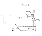
- Fig. 3 depicts schematically the connection of a separator device of the invention in a lubricating system of an engine.
- Engine oil from an oil pan 41 is pumped by the oil pump P3 through an oil screen S and supplied to a separator 42.
- Engine oil stripped of both solid and gaseous contaminants by the separator 42 is supplied to various parts B of an engine to be lubricated, and gas-rich oil is returned to the oil pan 41 through a gas removal pipe 43.
Landscapes
- Chemical & Material Sciences (AREA)
- Chemical Kinetics & Catalysis (AREA)
- Degasification And Air Bubble Elimination (AREA)
- Lubrication Details And Ventilation Of Internal Combustion Engines (AREA)
- Cyclones (AREA)
Abstract
Description
- In industrial applications requiring the handling fluids such as water, lubricants, chemical solutions, liquid foodstuffs and so forth, often it is necessary to remove solid contaminants from the fluid. For this purpose, it has been common practice to employ a fiber filter or a centrifugal filter.
- On the other hand, in order to prevent rust from forming and to prevent annoying noise in industrial water use, to prevent oil starvation in lubrication systems, to prevent inefficiency and inaccuracy in hydraulic systems and nonuniform quality in chemical or foodstuff materials, conventionally, devices employing buoyancy, vacuum and centrifugal force have been employed for removing gaseous contaminants, examples of which are disclosed in U.S. Patent No. 4,548,622.
- No compact and integrated device has heretofore been known, however, which is capable of simultaneously removing both solid and gaseous contaminants in a fluid.
- Such a device is particularly desirable though in the engine manufacturing industry. Moreover, as the rotational speed and output of automobile and motorcycle engines have lately been increased, the importance of removing gaseous as well as solid contaminants has increased. Excess gaseous contaminants in engine oil can cause serious difficulties, such as excess wear of lubricated parts due to oil starvation and a deterioration of the efficiency of the hydraulic valve lifters.
- On the other hand, the space available inside the engine compartment is generally not sufficient to accommodate both an oil filter and a gas separator. Hence, an integrated separator is desired, both from a standpoint of space and in terms of weight.
- Accordingly, an object of the present invention is to provide a compact and integrated separator for removing both solid and gaseous contaminants from fluids, for example, from engine oil.
- In accordance with the above and other objects, the invention provides a compact and integrated separator for removing both solid and gaseous contaminants from fluids, for example, from engine oil in which a vortex flow chamber for gas removal is combined with an oil filter for solid filtration.
- More specifically, the invention provides a separator device for removing both solid and gaseous contaminants from fluids including a filter system and a wall defining a vortex flow chamber which has a plurality of pores formed in the wall to permit fluids stripped of gaseous contaminants to pass therethrough. A fluid introduction pipe introduces fluids into the vortex flow chamber in a tangential direction of the chamber before or after the filter system passes the fluids. The wall defining the vortex flow chamber has a plurality of pores for passing fluids. A gas removal pipe extending into the vortex flow chamber and disposed substantially at the axial center of the vortex flow chamber has a plurality of small pores formed therein for allowing gas-rich fluids to pass therethrough. An outlet passage passes fluids which have passed through the filter and vortex flow chamber system.
-
- Fig. 1a is a cross-sectional view of an integrated separator constructed according to the present invention;
- Fig. 1b shows a cross section of the separator of Fig. 1a taken along a line X-Y in Fig. 1a;
- Fig. 2 is a cross-sectional view of another embodiment of an integrated separator of the invention; and
- Fig. 3 is a schematic diagram of an engine lubricating system in which the present invention can advantageously be used.
- Referring to the accompanying drawings, preferred embodiments of the present invention will be described in detail.
- Fig. 1a shows a cross-sectional view of a separator for a four-cycle internal combustion engine, which separator is constructed in accordance with the present invention.
- An oil pump P₁ pumps out oil containing solid and gaseous contaminants to the separator. The oil flow is introduced into the outside of the
filter element 3 of the filter system through inlet holes 1 and arubber check valve 2. The oil is filtered by thefilter element 3 then flows out throughmany holes 4 formed in the cylindrical wall 5 of the filter system. The filtered oil then flows to anupper chamber 6 separated by anupper wall 7 of the filter system through the space formed between the cylindrical wall 5 of the filter system and an inner cylindrical wall 8 located inside the filter system. The oil flows into an inlet pipe 9 disposed tangentially near the bottom (in the flow direction) 10 of the vortex flow chamber 11. Theconical wall 12 of the vortex flow chamber 11 is fixed at theedge 13 of the inner cylindrical wall 8. A portion of the oil flowing in a vortex pattern inside theconical wall 12 flows out through the pores 14 formed in theconical wall 12 at the part lower than thefixed edge 13, and the oil flows out of the device through theoutlet pore 15. - Due to the vortical flow of the oil in the vortex flow chamber 11 and the resulting centrifugal force acting on the oil, oil containing gaseous contaminants collects near the axial center of the flow. The gas-rich oil moves radially inwardly through small pores 16 formed in a
gas removal pipe 17 provided near the axial center of the vortex flow chamber 11. Thegas removal pipe 17 passes through the top wall of the conical vortex flow chamber 11. - A
relief valve 18 is disposed on theupper wall 7 of the filter system. A spring 19 is placed between the outside bottom of the vortex flow chamber 11 and the wall 19. - Fig. 1b shows a cross-sectional view of the separator of Fig. 1a taken along a line X-Y in Fig. 1a, specifically showing the region where the inlet pipe 9 extends tangentially into the
vortex chamber 3. - Fig. 2 shows a second preferred embodiment of the invention, also intended for use with a four-cycle internal combustion engine.
- An oil pump P₂ pumps out oil containing solid and gaseous contaminants to the separator through
inlet holes 21 and arubber check valve 22. The oil flow is introduced tangentially into avortex flow chamber 23, of which shape is conical, through aninlet pipe 24. A portion of the oil flowing in a vortex pattern inside theconical wall 25 flows out through the pores 26 formed in theconical wall 25 into a filter system which is disposed around the upper part of the conicalvortex flow chamber 23 and on anannular plate 30 fixed around theconical wall 25. The oil is filtered by afilter element 27 and passes throughsmall pores 28 formed in theouter wall 29 of the filter system and then flows out through theintermediate holes 31 formed in theupper plate 32 under which compriseshollow space 33 to pass the oil through theoutlet hole 34. - Due to the vortical flow of the oil in the
vortex flow chamber 23 and the resulting centrifugal force acting on the oil, oil containing gaseous contaminants collects near the axial center of the flow. The gas-rich oil moves radially inwardly throughsmall pores 33 formed in agas removal pipe 35 provided near the axial center of thevortex flow chamber 23. - The
gas removal pipe 35 passes through the top of the conicalvortex flow chamber 23, theupper wall 36 of the filter system and theouter wall 37. Tworelief valves inlet pipe 24 and theupper wall 36. A spring 40 is placed between the upperouter wall 37 and theupper wall 36 of the filter system. - Fig. 3 depicts schematically the connection of a separator device of the invention in a lubricating system of an engine.
- Engine oil from an oil pan 41 is pumped by the oil pump P₃ through an oil screen S and supplied to a separator 42. Engine oil stripped of both solid and gaseous contaminants by the separator 42 is supplied to various parts B of an engine to be lubricated, and gas-rich oil is returned to the oil pan 41 through a gas removal pipe 43.
- This completes the description of the preferred embodiments of the invention. Although preferred embodiments have been described, it is believed that numerous modifications and alterations thereto may be made without departing from the spirit and scope of the invention.
Claims (7)
Applications Claiming Priority (4)
| Application Number | Priority Date | Filing Date | Title |
|---|---|---|---|
| JP63118180A JPH01104315A (en) | 1987-07-30 | 1988-05-17 | Integrated separation/removal equipment of solid and/or gaseous foreign matter in lubricating oil |
| JP118180/88 | 1988-05-17 | ||
| JP202682/88 | 1988-08-16 | ||
| JP63202682A JPH0783807B2 (en) | 1988-08-16 | 1988-08-16 | Integrated separation and removal device for solid and gaseous foreign matter in liquid |
Publications (3)
| Publication Number | Publication Date |
|---|---|
| EP0342308A2 true EP0342308A2 (en) | 1989-11-23 |
| EP0342308A3 EP0342308A3 (en) | 1990-01-17 |
| EP0342308B1 EP0342308B1 (en) | 1993-12-29 |
Family
ID=26456163
Family Applications (1)
| Application Number | Title | Priority Date | Filing Date |
|---|---|---|---|
| EP89101124A Expired - Lifetime EP0342308B1 (en) | 1988-05-17 | 1989-01-23 | Integrated separator for solid and gaseous contaminants in a fluid |
Country Status (2)
| Country | Link |
|---|---|
| EP (1) | EP0342308B1 (en) |
| DE (1) | DE68911747T2 (en) |
Cited By (9)
| Publication number | Priority date | Publication date | Assignee | Title |
|---|---|---|---|---|
| EP0376443A3 (en) * | 1988-12-26 | 1990-12-19 | Mitsubishi Oil Company, Limited | Oil filter |
| EP0394585A3 (en) * | 1989-04-25 | 1990-12-27 | Mitsubishi Oil Company, Limited | Oil filter |
| EP0433042A3 (en) * | 1989-12-12 | 1991-07-24 | Mitsubishi Oil Company, Limited | Degasifying liquid pump |
| EP0430636A3 (en) * | 1989-11-27 | 1991-07-31 | Mitsubishi Oil Company, Limited | Gas removable pump for liquid |
| FR2684894A1 (en) * | 1991-12-16 | 1993-06-18 | Labinal | GAS FILTER. |
| FR2693663A1 (en) * | 1992-07-17 | 1994-01-21 | Lucas France | Liquid degasser filter. |
| EP0713720A1 (en) * | 1994-11-26 | 1996-05-29 | Knecht Filterwerke Gmbh | Oil filter |
| WO2009062498A1 (en) | 2007-11-15 | 2009-05-22 | Zf Friedrichshafen Ag | Oil reservoir comprising an oil filter |
| EP3348804A1 (en) * | 2017-01-13 | 2018-07-18 | MAN Truck & Bus AG | Lubricant container for a hydraulic system |
Families Citing this family (1)
| Publication number | Priority date | Publication date | Assignee | Title |
|---|---|---|---|---|
| JP4128085B2 (en) * | 2002-05-22 | 2008-07-30 | 株式会社小松製作所 | Liquid tank |
Family Cites Families (6)
| Publication number | Priority date | Publication date | Assignee | Title |
|---|---|---|---|---|
| DE1064752B (en) * | 1957-08-19 | 1959-09-03 | Charles A Winslow | Combined lubricant filter and air separation system |
| AT226483B (en) * | 1961-06-14 | 1963-03-25 | Alfred Knecht | Lubricating oil filters, in particular for internal combustion engines |
| US3486306A (en) * | 1968-04-05 | 1969-12-30 | Joseph J Blackmore | Liquid downflow air purging means for a vortex type de-aerator and the like |
| FR2086768A5 (en) * | 1970-04-08 | 1971-12-31 | Peugeot & Renault | |
| US3996027A (en) * | 1974-10-31 | 1976-12-07 | Baxter Laboratories, Inc. | Swirling flow bubble trap |
| JPS59158410U (en) * | 1983-04-12 | 1984-10-24 | 石川島播磨重工業株式会社 | Gas removal device in fluid |
-
1989
- 1989-01-23 EP EP89101124A patent/EP0342308B1/en not_active Expired - Lifetime
- 1989-01-23 DE DE89101124T patent/DE68911747T2/en not_active Expired - Fee Related
Cited By (12)
| Publication number | Priority date | Publication date | Assignee | Title |
|---|---|---|---|---|
| EP0376443A3 (en) * | 1988-12-26 | 1990-12-19 | Mitsubishi Oil Company, Limited | Oil filter |
| EP0394585A3 (en) * | 1989-04-25 | 1990-12-27 | Mitsubishi Oil Company, Limited | Oil filter |
| EP0430636A3 (en) * | 1989-11-27 | 1991-07-31 | Mitsubishi Oil Company, Limited | Gas removable pump for liquid |
| EP0433042A3 (en) * | 1989-12-12 | 1991-07-24 | Mitsubishi Oil Company, Limited | Degasifying liquid pump |
| FR2684894A1 (en) * | 1991-12-16 | 1993-06-18 | Labinal | GAS FILTER. |
| EP0547951A1 (en) * | 1991-12-16 | 1993-06-23 | Filtrauto | Gasoil filter |
| FR2693663A1 (en) * | 1992-07-17 | 1994-01-21 | Lucas France | Liquid degasser filter. |
| US5382361A (en) * | 1992-07-17 | 1995-01-17 | Lucas Industries Public Limited Company | Liquid and entrained air filter |
| EP0713720A1 (en) * | 1994-11-26 | 1996-05-29 | Knecht Filterwerke Gmbh | Oil filter |
| WO2009062498A1 (en) | 2007-11-15 | 2009-05-22 | Zf Friedrichshafen Ag | Oil reservoir comprising an oil filter |
| US8449767B2 (en) | 2007-11-15 | 2013-05-28 | Robert Bosch Gmbh | Oil reservoir comprising an oil filter |
| EP3348804A1 (en) * | 2017-01-13 | 2018-07-18 | MAN Truck & Bus AG | Lubricant container for a hydraulic system |
Also Published As
| Publication number | Publication date |
|---|---|
| DE68911747T2 (en) | 1994-04-28 |
| EP0342308B1 (en) | 1993-12-29 |
| DE68911747D1 (en) | 1994-02-10 |
| EP0342308A3 (en) | 1990-01-17 |
Similar Documents
| Publication | Publication Date | Title |
|---|---|---|
| US4865632A (en) | Integrated separator for solid and gaseous contaminants in a fluid | |
| US4878924A (en) | Integrated separator for solid and gas contaminants in engine oil | |
| EP0400202B1 (en) | Gas liquid separator | |
| US4298465A (en) | Fuel filter and water separator apparatus | |
| KR960001377B1 (en) | Oil filter | |
| US4626348A (en) | End cap which will accommodate flow reversal | |
| US4655914A (en) | Method and apparatus for filtering impurities out of fluid | |
| US6858067B2 (en) | Filtration vessel and method for rotary gas compressor system | |
| AU569459B2 (en) | Repelling- action filter unit and assembly | |
| EP0236115A2 (en) | Self-cleaning fluid filter | |
| EP0342308A2 (en) | Integrated separator for solid and gaseous contaminants in a fluid | |
| EP0394585B1 (en) | Oil filter | |
| US5114575A (en) | Oil filter | |
| US4312751A (en) | Centrifugal water separator | |
| WO2019084440A1 (en) | Integrated module with stage one and stage two filters combined in single housing | |
| CA1298168C (en) | Integrated relief valve with gas separator for fluid | |
| KR970000334B1 (en) | Gas removal pump for liquid | |
| EP0487231A2 (en) | Oil filter | |
| US4544483A (en) | Dynamic, reverse-flow oil purifier device | |
| EP0439901A1 (en) | Oil filter | |
| CA2051944A1 (en) | Oil filter having gas separator | |
| JPH05296018A (en) | Oil pan with built-in bubble remover | |
| JP2000312840A (en) | Apparatus for separating heavy and light components in mixed fluid | |
| JPH0745002B2 (en) | Bubble removal system in liquid | |
| JPS6127603Y2 (en) |
Legal Events
| Date | Code | Title | Description |
|---|---|---|---|
| PUAI | Public reference made under article 153(3) epc to a published international application that has entered the european phase |
Free format text: ORIGINAL CODE: 0009012 |
|
| AK | Designated contracting states |
Kind code of ref document: A2 Designated state(s): DE FR GB |
|
| PUAL | Search report despatched |
Free format text: ORIGINAL CODE: 0009013 |
|
| AK | Designated contracting states |
Kind code of ref document: A3 Designated state(s): DE FR GB |
|
| 17P | Request for examination filed |
Effective date: 19900712 |
|
| 17Q | First examination report despatched |
Effective date: 19911125 |
|
| GRAA | (expected) grant |
Free format text: ORIGINAL CODE: 0009210 |
|
| AK | Designated contracting states |
Kind code of ref document: B1 Designated state(s): DE FR GB |
|
| REF | Corresponds to: |
Ref document number: 68911747 Country of ref document: DE Date of ref document: 19940210 |
|
| ET | Fr: translation filed | ||
| PLBE | No opposition filed within time limit |
Free format text: ORIGINAL CODE: 0009261 |
|
| STAA | Information on the status of an ep patent application or granted ep patent |
Free format text: STATUS: NO OPPOSITION FILED WITHIN TIME LIMIT |
|
| 26N | No opposition filed | ||
| REG | Reference to a national code |
Ref country code: FR Ref legal event code: TP |
|
| REG | Reference to a national code |
Ref country code: GB Ref legal event code: 732E |
|
| REG | Reference to a national code |
Ref country code: GB Ref legal event code: IF02 |
|
| PGFP | Annual fee paid to national office [announced via postgrant information from national office to epo] |
Ref country code: FR Payment date: 20020110 Year of fee payment: 14 |
|
| PGFP | Annual fee paid to national office [announced via postgrant information from national office to epo] |
Ref country code: GB Payment date: 20020123 Year of fee payment: 14 |
|
| PGFP | Annual fee paid to national office [announced via postgrant information from national office to epo] |
Ref country code: DE Payment date: 20020227 Year of fee payment: 14 |
|
| PG25 | Lapsed in a contracting state [announced via postgrant information from national office to epo] |
Ref country code: GB Free format text: LAPSE BECAUSE OF NON-PAYMENT OF DUE FEES Effective date: 20030123 |
|
| PG25 | Lapsed in a contracting state [announced via postgrant information from national office to epo] |
Ref country code: DE Free format text: LAPSE BECAUSE OF NON-PAYMENT OF DUE FEES Effective date: 20030801 |
|
| GBPC | Gb: european patent ceased through non-payment of renewal fee | ||
| PG25 | Lapsed in a contracting state [announced via postgrant information from national office to epo] |
Ref country code: FR Free format text: LAPSE BECAUSE OF NON-PAYMENT OF DUE FEES Effective date: 20030930 |
|
| REG | Reference to a national code |
Ref country code: FR Ref legal event code: ST |