EP0342294A1 - Abschussvorrichtung für drallstabilisierte Selbstantriebsgeschosse - Google Patents
Abschussvorrichtung für drallstabilisierte Selbstantriebsgeschosse Download PDFInfo
- Publication number
- EP0342294A1 EP0342294A1 EP88311952A EP88311952A EP0342294A1 EP 0342294 A1 EP0342294 A1 EP 0342294A1 EP 88311952 A EP88311952 A EP 88311952A EP 88311952 A EP88311952 A EP 88311952A EP 0342294 A1 EP0342294 A1 EP 0342294A1
- Authority
- EP
- European Patent Office
- Prior art keywords
- missile
- nozzle
- rotary
- release mechanism
- projectile
- Prior art date
- Legal status (The legal status is an assumption and is not a legal conclusion. Google has not performed a legal analysis and makes no representation as to the accuracy of the status listed.)
- Withdrawn
Links
- 230000007246 mechanism Effects 0.000 claims abstract description 31
- 238000000926 separation method Methods 0.000 claims abstract description 27
- 230000033001 locomotion Effects 0.000 claims abstract description 23
- 239000007789 gas Substances 0.000 claims abstract description 16
- 230000000694 effects Effects 0.000 claims abstract description 9
- 238000010438 heat treatment Methods 0.000 claims abstract description 7
- 230000002093 peripheral effect Effects 0.000 claims description 2
- 230000008878 coupling Effects 0.000 description 9
- 238000010168 coupling process Methods 0.000 description 9
- 238000005859 coupling reaction Methods 0.000 description 9
- PRPINYUDVPFIRX-UHFFFAOYSA-N 1-naphthaleneacetic acid Chemical compound C1=CC=C2C(CC(=O)O)=CC=CC2=C1 PRPINYUDVPFIRX-UHFFFAOYSA-N 0.000 description 3
- 230000036316 preload Effects 0.000 description 3
- 238000005219 brazing Methods 0.000 description 2
- 238000010304 firing Methods 0.000 description 2
- 230000006872 improvement Effects 0.000 description 2
- 230000013011 mating Effects 0.000 description 2
- 230000009467 reduction Effects 0.000 description 2
- 230000003578 releasing effect Effects 0.000 description 2
- 230000000452 restraining effect Effects 0.000 description 2
- 238000009987 spinning Methods 0.000 description 2
- 235000015842 Hesperis Nutrition 0.000 description 1
- 235000012633 Iberis amara Nutrition 0.000 description 1
- 230000009471 action Effects 0.000 description 1
- 230000004913 activation Effects 0.000 description 1
- 238000007792 addition Methods 0.000 description 1
- 239000000956 alloy Substances 0.000 description 1
- 229910045601 alloy Inorganic materials 0.000 description 1
- 230000000712 assembly Effects 0.000 description 1
- 238000000429 assembly Methods 0.000 description 1
- 230000005540 biological transmission Effects 0.000 description 1
- 238000006243 chemical reaction Methods 0.000 description 1
- 238000010276 construction Methods 0.000 description 1
- 230000003628 erosive effect Effects 0.000 description 1
- 238000003754 machining Methods 0.000 description 1
- 230000014759 maintenance of location Effects 0.000 description 1
- 238000004519 manufacturing process Methods 0.000 description 1
- 230000008018 melting Effects 0.000 description 1
- 238000002844 melting Methods 0.000 description 1
- 238000009527 percussion Methods 0.000 description 1
- 230000002028 premature Effects 0.000 description 1
- 239000003380 propellant Substances 0.000 description 1
- 230000001141 propulsive effect Effects 0.000 description 1
- 230000003313 weakening effect Effects 0.000 description 1
Images
Classifications
-
- F—MECHANICAL ENGINEERING; LIGHTING; HEATING; WEAPONS; BLASTING
- F41—WEAPONS
- F41F—APPARATUS FOR LAUNCHING PROJECTILES OR MISSILES FROM BARRELS, e.g. CANNONS; LAUNCHERS FOR ROCKETS OR TORPEDOES; HARPOON GUNS
- F41F3/00—Rocket or torpedo launchers
- F41F3/04—Rocket or torpedo launchers for rockets
- F41F3/048—Means for imparting spin to the rocket before launching
-
- F—MECHANICAL ENGINEERING; LIGHTING; HEATING; WEAPONS; BLASTING
- F41—WEAPONS
- F41C—SMALLARMS, e.g. PISTOLS, RIFLES; ACCESSORIES THEREFOR
- F41C27/00—Accessories; Details or attachments not otherwise provided for
- F41C27/06—Adaptations of smallarms for firing grenades, e.g. rifle grenades, or for firing riot-control ammunition; Barrel attachments therefor
Definitions
- This invention generally relates to a projectile release mechanism and, particularly, to a release mechanism for facilitating launching a spin-stabilized self-propelled missile.
- the projectiles spins about an axis upwardly inclined relative to the intended straight line path of flight and aligned with the missile propulsion thrust axis.
- the missile is released following ignition or activation of the propulsion system within the missile.
- the propulsion is effected by the reaction of the exhaust jet of, for example, a rocket motor housed within the spherical missile shell.
- Such spin-stabilized spherical self-propelled missiles experience difficulties in remaining stabilized during attainment of desired rotational speed and in coordinating the spinning and release of the missile. Release of the missile prior to attainment of the adequate rotational speed can result in unstable flight. Delay of release after attainment of adequate rotational speed can result in a loss of propulsive range.
- the separate fusible link member is of the nature of a brazing alloy serving as one part of a nozzle assembly to secure the rocket to the rotary support means.
- the fusible link member is brazed between two separate fore and aft nozzle portions which are permanently secured to the missile and to the support means, respectively, as by threaded engagements.
- the present invention represents somewhat of a radical departure from the prior art in that a mass is caused to be urged or propelled rearwardly by the gases of the missile or separate or combined other force generating mechanism to strike an abutment means on the turbine or rotary means for the missile to cause the rotary means in its receptacle, to move rapidly away from the missile after separation of the fusible joint means.
- the present invention thus allows positive missile retention by the launch system rotary means during coupling fusing and therefore eliminates pointing error tip off forces initiated by the coupling fusing in any of the prior art.
- An object, therefore, of the present invention is to provide a new and improved projectile release mechanism for facilitating lauching a self-propelled projectile, particularly a spin-stabilized missile.
- the mechanism includes missile support means having rotary means including receptacle means defining a spin axis, and fixed support means for supporting the rotary means for rotation about the spin axis as well as for movement axially of the spin axis.
- Nozzle means extend from the missile into the receptacle means, including fusible joint means for heating by high-temperature exhaust gases expelled by the missile to release the missile, and an aft nozzle section is movable away from the missile on fusing and separation of the fusible joint means.
- Abutment means are formed on the rotary means in the path of movement of the aft nozzle section for striking by the aft nozzle section to effect rapid movement of the rotary means and receptacle means axially away from the missile following fusing and separation of the fusible joint means and on impact of the aft nozzle means with the rotary means abutment.
- spring biasing means are operatively associated between the rotary means and the nozzle means, particularly the aft section of the nozzle means, for holding the nozzle means and, thereby, the missile in the receptacle means.
- detent means are provided between the rotary means and the fixed support means to prevent premature motion and post separation recoil of the rotary means after striking by the aft section of the support means.
- Another feature of the invention includes a register section on the support means for receiving the missile, the register section and the missile having complementarily engageable, axially spaced concentric land means to insure proper alignment of the missile.
- One of the axially spaced land means, the forward land means shown herein, is of a cylindrical configuration, and the other or rear land means is of a forwardly opening conical configuration.
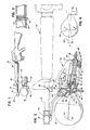
- a substantially spherical, spin-stabilized, self-propelled missile 10 is shown mounted to the front of a barrel 12 of an assault weapon such as a rifle, generally designated 14.
- the rifle shown is a standard M-16A2 military rifle or any similar device.
- a missile support means generally designated 16, include a front upper attachment portion 18 with axial motion restraint 19 and a rear attachement portion, generally designated 20.
- Bracket portion 18 is positioned on the barrel 12 whereby part of the gas emanating from the barrel is channeled through a passageway 22 (Fig. 2) to a firing pin assembly, generally designated 24, which is effective to strike a primer on missile 10 to ignite the rocket propellant therein, as is known in the art.
- the latch and the axial motion restraint means 19 are provided to lock support means 16 onto the rifle barrel.
- Support means 16 also include turbine support portions 28 and 30 which support the missile and release mechanism on an axis 32 upwardly inclined relative to an intended straight-line path of flight 34 generally parallel to the axis of rifle barrel 12.
- axis 32 is the spin axis of missile 10; i.e. the motor thrust axis of the missile rocket motor.
- Axis 34 which defines the line of flight of the missile is the forward velocity component thereof.
- the self-propelled missile 10 is a spinning projectile launched from essentially a zero-length launcher. In other words, this is in contrast to a bullet which travels through the entire length of the rifle barrel.
- the missile must be maintained in constant alignment with spin axis 32 during spin-up and release.
- the missile release must be practically instantaneous in order to prevent launcher/projectile impulse moments from redirecting the missile during and immediately after release.
- the present invention addresses these problems and has been shown to be effective in assuring an undisturbed spin-up and launch event not heretofore available with the prior art.
- turbine rotary means include a plurality of turbine nozzles 38.
- four nozzles are provided, 90 degrees apart, to provide uniform and equalized torque transmission forces.
- Four turbines are used to reduce pressure drop variations across the coupling ports and equalize the exhaust gas flow through the coupling ports.
- the multiplicity of turbine arms accomplishes this by reducing the back pressure in the turbine plenum located between the coupling and the turbine air inlets and allowing smoother more evenly distributed exhaust flow through the coupling, coupling ports, turbine plenum and turbine arms.
- rotary means 36 is rotatable within turbine support portions 28 and 30 by appropriate bearing means.
- the rotary means has a forward missile register section 40 for mating with missile 10, as described hereinafter, an intermediate receptacle section 42 journalled in support portion 28, and a rear distal end section 44 journalled in support portion 30.
- missile register section 40, receptacle section 42 and rear distal end section 44 are generally coaxial with spin axis 32.
- Intermediate receptacle section 42 of turbine rotary means 36 forms receptacle means for the nozzle assembly on spin axis 32.
- the fusible joint means 52 is similar to that shown in the aforementioned U.S. Patent No. 4,395,836 and is disposed for heating by high-temperature exhaust gases expelled by missile 10 to release the missile from support means 16 and particularly from rotary turbine means 36. Details of such a fusible joint means can be derived from the aforesaid patent which is incorporated herein by reference.
- nozzle section 48 is a one-piece homogeneous nozzle member.
- a peripheral ring portion 57 is reduced in sectional thickness by appropriate machining operations.
- a precise pattern of equally spaced axially extending slots or passages 57a form the fusible joint which is an integral part of the one-piece nozzle member and which is separated by the high-temperature exhaust gases expelled by missile 10.
- the slots versus the round holes of the aforementioned patent, provide an area which is more uniformly heated under the influence of a spring preload, and separates more nearly instantaneously (e.g. 0.001 seconds) across the whole transverse "plane" defined by the slots, with a minimum loss of preload prior to separation.
- aft nozzle section 50 can move rearwardly in the direction of arrow "A" within receptacle section 42 of rotary turbine means 36.
- An axial slot 54 in receptacle section 42 guides a pin 56 extending therethrough and into aft nozzle section 50, thereby transmitting turbine torque to the missile 10.
- the aft section contains slots that vent exhaust gases after separation of the fusible joint.
- the substantially zero-length launching and substantially instantaneous release of missile 10 is significantly facilitated by a unique mounting of rotary turbine means 36 in support means 16.
- the missile 10 is seated firmly in the register section 40 of rotary means 36 through the agency of a coil spring 58, bearing against the termination of rear distal end section 44 of the rotary turbine means and a washer 60 fixed to a rod 62 which, in turn, is fixed to aft nozzle section 50.
- the forward position of rotary means 36 is limited by a snap ring and washer assembly 64 so as to properly align the missile's percussion cap with firing pin assembly 24. Its aft location is fixed by plunger means 72, described hereinafter.
- aft nozzle section 50 Upon fusing or failure of fusible joint means 52, aft nozzle section 50 recoils rearwardly under the action of the rocket motor gases and the preload of spring 58. The aft nozzle section moves rearwardly in the direction of arrow "A" and this recoiling mass strikes an abutment seat 66 on the interior of rotary turbine means 36.
- the kinetic energy of the recoiling mass is transferred to the rotary turbine means and is sufficient to overcome the load of spring loaded plunger 72, accelerating the rotary turbine means in an aft direction, stripping the mating lands (described hereinafter) between register section 40 of the rotary turbine means 36 and missile 10, leaving the missile free and with sufficient clearance to preclude recontact producing tipoff forces regardless of rifle/launcher motions.
- Rearward movement of the rotary turbine means is limited by a shoulder 68 which comes into engagement with the front of support means 16, at support portion 28.
- the invention provides a high speed (microseconds) separation for a more slowly moving projectile.
- detent means 70 which will project into the path of a ramp latch flange 74.
- the detent means is in the form of a spring loaded plunger 72 which bears against the ramped flange 74 about the distal end section 44 of the rotary turbine means, thus positioning the turbine in the rearward direction.
- Another feature of the invention includes the provision of complementarily engageable, axially spaced concentric land means on register section 40 of rotary turbine means 36. More particularly, this interface comprises a large-diameter, cylindrical forward land 76 and a small-diameter, shallow angle conical aft land 70, both lands being concentric to missile spin axis 32.
- the two axially spaced land means are held in position axially by the spring loading (i.e. spring 58) between nozzle 46 and rotary turbine means 36, as described above.
- cylindrical land means 76 and conical land 78 can be machined within fine tolerances to maintain concentricity of the interfacing components and also provides a surface for carrying axial loads. Yet, conical land means 78 still affords the necessary seal for the mechanism.
- tip off forces "F” cause tip off moments "M”.
- the time "t" in the error equation has been relatively large (e.g. 10 milliseconds).
Landscapes
- Engineering & Computer Science (AREA)
- General Engineering & Computer Science (AREA)
- Aiming, Guidance, Guns With A Light Source, Armor, Camouflage, And Targets (AREA)
- Toys (AREA)
Applications Claiming Priority (2)
| Application Number | Priority Date | Filing Date | Title |
|---|---|---|---|
| US07/195,657 US5067386A (en) | 1988-05-18 | 1988-05-18 | Release apparatus for spin stabilized self-propelled projectiles |
| US195657 | 1988-05-18 |
Publications (1)
| Publication Number | Publication Date |
|---|---|
| EP0342294A1 true EP0342294A1 (de) | 1989-11-23 |
Family
ID=22722229
Family Applications (1)
| Application Number | Title | Priority Date | Filing Date |
|---|---|---|---|
| EP88311952A Withdrawn EP0342294A1 (de) | 1988-05-18 | 1988-12-16 | Abschussvorrichtung für drallstabilisierte Selbstantriebsgeschosse |
Country Status (4)
| Country | Link |
|---|---|
| US (1) | US5067386A (de) |
| EP (1) | EP0342294A1 (de) |
| KR (1) | KR920005979B1 (de) |
| IL (1) | IL88782A (de) |
Cited By (3)
| Publication number | Priority date | Publication date | Assignee | Title |
|---|---|---|---|---|
| EP0467515A1 (de) * | 1990-07-19 | 1992-01-22 | Brunswick Corporation | Verfahren und Vorrichtung zum Ausrichten von drallstabilisierten Selbstantriebsgeschossen |
| EP0470684A1 (de) * | 1990-08-06 | 1992-02-12 | Brunswick Corporation | Auslösemechanismus für drallstabilisierte Selbstantriebsgeschosse |
| US6134823A (en) * | 1997-09-11 | 2000-10-24 | R/M Equipment, Inc. | Apparatus for attaching a supplemental device to a minimally altered host firearm |
Families Citing this family (4)
| Publication number | Priority date | Publication date | Assignee | Title |
|---|---|---|---|---|
| FR2734629B1 (fr) * | 1995-05-23 | 1997-07-25 | Giat Ind Sa | Accessoire d'arme a feu portative |
| US6269748B1 (en) * | 1998-06-18 | 2001-08-07 | Nea Electronics, Inc. | Release mechanism |
| US7552729B2 (en) * | 2001-03-05 | 2009-06-30 | The United States Of America As Represented By The Secretary Of The Army | Intubation device and method |
| US20110214329A1 (en) * | 2010-03-08 | 2011-09-08 | Timmy Lee Green | Weapon accessory mounting adapter |
Citations (2)
| Publication number | Priority date | Publication date | Assignee | Title |
|---|---|---|---|---|
| US4395836A (en) * | 1980-11-13 | 1983-08-02 | Brunswick Corporation | Release apparatus for jet-propelled projectiles |
| US4403435A (en) * | 1981-04-02 | 1983-09-13 | Brunswick Corporation | Release and alignment mechanism for jet-propelled projectiles |
Family Cites Families (4)
| Publication number | Priority date | Publication date | Assignee | Title |
|---|---|---|---|---|
| US3554078A (en) * | 1969-02-10 | 1971-01-12 | Joseph S Horvath | Spherical missile and launching means therefor |
| US3611867A (en) * | 1969-11-03 | 1971-10-12 | Us Army | Emergency weapon for firing high-velocity grenade rounds |
| US4060117A (en) * | 1976-04-12 | 1977-11-29 | General Motors Corporation | Inertial ring lock |
| US4270293A (en) * | 1979-04-05 | 1981-06-02 | The United States Of America As Represented By The Secretary Of The Army | Device for launching non-lethal ring airfoil projectiles |
-
1988
- 1988-05-18 US US07/195,657 patent/US5067386A/en not_active Expired - Fee Related
- 1988-12-16 EP EP88311952A patent/EP0342294A1/de not_active Withdrawn
- 1988-12-23 IL IL8878288A patent/IL88782A/en not_active IP Right Cessation
-
1989
- 1989-03-14 KR KR1019890003091A patent/KR920005979B1/ko not_active Expired
Patent Citations (2)
| Publication number | Priority date | Publication date | Assignee | Title |
|---|---|---|---|---|
| US4395836A (en) * | 1980-11-13 | 1983-08-02 | Brunswick Corporation | Release apparatus for jet-propelled projectiles |
| US4403435A (en) * | 1981-04-02 | 1983-09-13 | Brunswick Corporation | Release and alignment mechanism for jet-propelled projectiles |
Cited By (5)
| Publication number | Priority date | Publication date | Assignee | Title |
|---|---|---|---|---|
| EP0467515A1 (de) * | 1990-07-19 | 1992-01-22 | Brunswick Corporation | Verfahren und Vorrichtung zum Ausrichten von drallstabilisierten Selbstantriebsgeschossen |
| TR25817A (tr) * | 1990-07-19 | 1993-09-01 | Brunswick Corp | DÖNME STABILIZELI KENDINDEN TERCIHLI FüZELERIN AYARLANMASI ICIN YÖNTEM VE CIHAZ |
| EP0470684A1 (de) * | 1990-08-06 | 1992-02-12 | Brunswick Corporation | Auslösemechanismus für drallstabilisierte Selbstantriebsgeschosse |
| US6134823A (en) * | 1997-09-11 | 2000-10-24 | R/M Equipment, Inc. | Apparatus for attaching a supplemental device to a minimally altered host firearm |
| US6453594B1 (en) | 1997-09-11 | 2002-09-24 | R/M Equipment, Inc. | Apparatus for attaching a supplemental device to a minimally altered host firearm |
Also Published As
| Publication number | Publication date |
|---|---|
| KR920005979B1 (ko) | 1992-07-25 |
| US5067386A (en) | 1991-11-26 |
| KR890017518A (ko) | 1989-12-16 |
| IL88782A (en) | 1994-04-12 |
| IL88782A0 (en) | 1989-07-31 |
Similar Documents
| Publication | Publication Date | Title |
|---|---|---|
| US7947938B2 (en) | Methods and apparatus for projectile guidance | |
| US6126109A (en) | Unlocking tail fin assembly for guided projectiles | |
| KR100796706B1 (ko) | 교환 가능한 페이로드를 포함하는 포 발사체 | |
| US5067386A (en) | Release apparatus for spin stabilized self-propelled projectiles | |
| US6745696B1 (en) | Armor piercing projectile | |
| EP2659219B1 (de) | Geschoss | |
| CZ287507B6 (en) | Ammunition for a weapon of small, medium or great caliber | |
| RU2239782C1 (ru) | Реактивный снаряд | |
| EP0131074B1 (de) | Vorrichtung zum Freigeben und Ausrichten rückstossgetriebener Geschosse | |
| US7806053B1 (en) | Method and apparatus for changing the spin of a projectile in flight | |
| RU2133445C1 (ru) | Реактивный снаряд с отделяемым двигателем | |
| US3705550A (en) | Solid rocket thrust termination device | |
| JPH06221800A (ja) | 砲身前域用安全信管および該砲身前域用安全信管を装備した砲弾 | |
| US4395836A (en) | Release apparatus for jet-propelled projectiles | |
| US5115709A (en) | Release mechanism for spin-stabilized self-propelled missiles | |
| RU2237856C2 (ru) | Бронебойный реактивный снаряд | |
| US4258625A (en) | Ball-actuated tubular projectile | |
| CN115962687A (zh) | 一种40mm火箭筒用可分离式制导火箭弹 | |
| KR102747917B1 (ko) | 위치 자세 제어 장치를 동체로 활용하는 직격 요격체 및 이를 갖는 유도무기 | |
| EP0467515B1 (de) | Verfahren und Vorrichtung zum Ausrichten von drallstabilisierten Selbstantriebsgeschossen | |
| RU2125229C1 (ru) | Реактивный артиллерийский снаряд | |
| IL97445A (en) | A mechanism for releasing self-propelled and stabilized missiles by rotation | |
| US4604953A (en) | Void-sensing fuze | |
| RU2157504C1 (ru) | Реактивный снаряд с отделяемым двигателем | |
| JPH05164499A (ja) | 旋動安定自走式ミサイル用解放機構 |
Legal Events
| Date | Code | Title | Description |
|---|---|---|---|
| PUAI | Public reference made under article 153(3) epc to a published international application that has entered the european phase |
Free format text: ORIGINAL CODE: 0009012 |
|
| AK | Designated contracting states |
Kind code of ref document: A1 Designated state(s): DE FR GB SE |
|
| 17P | Request for examination filed |
Effective date: 19900516 |
|
| 17Q | First examination report despatched |
Effective date: 19921216 |
|
| STAA | Information on the status of an ep patent application or granted ep patent |
Free format text: STATUS: THE APPLICATION IS DEEMED TO BE WITHDRAWN |
|
| 18D | Application deemed to be withdrawn |
Effective date: 19941103 |