EP0341941A1 - Method and apparatus for lining a buried pipe with a polymer liner - Google Patents
Method and apparatus for lining a buried pipe with a polymer liner Download PDFInfo
- Publication number
- EP0341941A1 EP0341941A1 EP89304599A EP89304599A EP0341941A1 EP 0341941 A1 EP0341941 A1 EP 0341941A1 EP 89304599 A EP89304599 A EP 89304599A EP 89304599 A EP89304599 A EP 89304599A EP 0341941 A1 EP0341941 A1 EP 0341941A1
- Authority
- EP
- European Patent Office
- Prior art keywords
- die
- liner
- pipe
- diameter
- throat
- Prior art date
- Legal status (The legal status is an assumption and is not a legal conclusion. Google has not performed a legal analysis and makes no representation as to the accuracy of the status listed.)
- Granted
Links
Images


Classifications
-
- F—MECHANICAL ENGINEERING; LIGHTING; HEATING; WEAPONS; BLASTING
- F16—ENGINEERING ELEMENTS AND UNITS; GENERAL MEASURES FOR PRODUCING AND MAINTAINING EFFECTIVE FUNCTIONING OF MACHINES OR INSTALLATIONS; THERMAL INSULATION IN GENERAL
- F16L—PIPES; JOINTS OR FITTINGS FOR PIPES; SUPPORTS FOR PIPES, CABLES OR PROTECTIVE TUBING; MEANS FOR THERMAL INSULATION IN GENERAL
- F16L58/00—Protection of pipes or pipe fittings against corrosion or incrustation
- F16L58/02—Protection of pipes or pipe fittings against corrosion or incrustation by means of internal or external coatings
-
- F—MECHANICAL ENGINEERING; LIGHTING; HEATING; WEAPONS; BLASTING
- F16—ENGINEERING ELEMENTS AND UNITS; GENERAL MEASURES FOR PRODUCING AND MAINTAINING EFFECTIVE FUNCTIONING OF MACHINES OR INSTALLATIONS; THERMAL INSULATION IN GENERAL
- F16L—PIPES; JOINTS OR FITTINGS FOR PIPES; SUPPORTS FOR PIPES, CABLES OR PROTECTIVE TUBING; MEANS FOR THERMAL INSULATION IN GENERAL
- F16L55/00—Devices or appurtenances for use in, or in connection with, pipes or pipe systems
- F16L55/16—Devices for covering leaks in pipes or hoses, e.g. hose-menders
- F16L55/162—Devices for covering leaks in pipes or hoses, e.g. hose-menders from inside the pipe
- F16L55/165—Devices for covering leaks in pipes or hoses, e.g. hose-menders from inside the pipe a pipe or flexible liner being inserted in the damaged section
- F16L55/1652—Devices for covering leaks in pipes or hoses, e.g. hose-menders from inside the pipe a pipe or flexible liner being inserted in the damaged section the flexible liner being pulled into the damaged section
-
- B—PERFORMING OPERATIONS; TRANSPORTING
- B29—WORKING OF PLASTICS; WORKING OF SUBSTANCES IN A PLASTIC STATE IN GENERAL
- B29C—SHAPING OR JOINING OF PLASTICS; SHAPING OF MATERIAL IN A PLASTIC STATE, NOT OTHERWISE PROVIDED FOR; AFTER-TREATMENT OF THE SHAPED PRODUCTS, e.g. REPAIRING
- B29C53/00—Shaping by bending, folding, twisting, straightening or flattening; Apparatus therefor
- B29C53/02—Bending or folding
- B29C53/08—Bending or folding of tubes or other profiled members
- B29C53/086—Bending or folding of tubes or other profiled members bending radially, i.e. deformig the cross-section of the tube
-
- B—PERFORMING OPERATIONS; TRANSPORTING
- B29—WORKING OF PLASTICS; WORKING OF SUBSTANCES IN A PLASTIC STATE IN GENERAL
- B29C—SHAPING OR JOINING OF PLASTICS; SHAPING OF MATERIAL IN A PLASTIC STATE, NOT OTHERWISE PROVIDED FOR; AFTER-TREATMENT OF THE SHAPED PRODUCTS, e.g. REPAIRING
- B29C63/00—Lining or sheathing, i.e. applying preformed layers or sheathings of plastics; Apparatus therefor
- B29C63/26—Lining or sheathing of internal surfaces
- B29C63/34—Lining or sheathing of internal surfaces using tubular layers or sheathings
-
- F—MECHANICAL ENGINEERING; LIGHTING; HEATING; WEAPONS; BLASTING
- F16—ENGINEERING ELEMENTS AND UNITS; GENERAL MEASURES FOR PRODUCING AND MAINTAINING EFFECTIVE FUNCTIONING OF MACHINES OR INSTALLATIONS; THERMAL INSULATION IN GENERAL
- F16L—PIPES; JOINTS OR FITTINGS FOR PIPES; SUPPORTS FOR PIPES, CABLES OR PROTECTIVE TUBING; MEANS FOR THERMAL INSULATION IN GENERAL
- F16L55/00—Devices or appurtenances for use in, or in connection with, pipes or pipe systems
- F16L55/16—Devices for covering leaks in pipes or hoses, e.g. hose-menders
- F16L55/162—Devices for covering leaks in pipes or hoses, e.g. hose-menders from inside the pipe
- F16L55/165—Devices for covering leaks in pipes or hoses, e.g. hose-menders from inside the pipe a pipe or flexible liner being inserted in the damaged section
- F16L55/1656—Devices for covering leaks in pipes or hoses, e.g. hose-menders from inside the pipe a pipe or flexible liner being inserted in the damaged section materials for flexible liners
-
- B—PERFORMING OPERATIONS; TRANSPORTING
- B29—WORKING OF PLASTICS; WORKING OF SUBSTANCES IN A PLASTIC STATE IN GENERAL
- B29L—INDEXING SCHEME ASSOCIATED WITH SUBCLASS B29C, RELATING TO PARTICULAR ARTICLES
- B29L2023/00—Tubular articles
- B29L2023/22—Tubes or pipes, i.e. rigid
-
- Y—GENERAL TAGGING OF NEW TECHNOLOGICAL DEVELOPMENTS; GENERAL TAGGING OF CROSS-SECTIONAL TECHNOLOGIES SPANNING OVER SEVERAL SECTIONS OF THE IPC; TECHNICAL SUBJECTS COVERED BY FORMER USPC CROSS-REFERENCE ART COLLECTIONS [XRACs] AND DIGESTS
- Y10—TECHNICAL SUBJECTS COVERED BY FORMER USPC
- Y10T—TECHNICAL SUBJECTS COVERED BY FORMER US CLASSIFICATION
- Y10T29/00—Metal working
- Y10T29/49—Method of mechanical manufacture
- Y10T29/49718—Repairing
- Y10T29/49732—Repairing by attaching repair preform, e.g., remaking, restoring, or patching
-
- Y—GENERAL TAGGING OF NEW TECHNOLOGICAL DEVELOPMENTS; GENERAL TAGGING OF CROSS-SECTIONAL TECHNOLOGIES SPANNING OVER SEVERAL SECTIONS OF THE IPC; TECHNICAL SUBJECTS COVERED BY FORMER USPC CROSS-REFERENCE ART COLLECTIONS [XRACs] AND DIGESTS
- Y10—TECHNICAL SUBJECTS COVERED BY FORMER USPC
- Y10T—TECHNICAL SUBJECTS COVERED BY FORMER US CLASSIFICATION
- Y10T29/00—Metal working
- Y10T29/49—Method of mechanical manufacture
- Y10T29/49826—Assembling or joining
- Y10T29/49863—Assembling or joining with prestressing of part
- Y10T29/4987—Elastic joining of parts
- Y10T29/49872—Confining elastic part in socket
Definitions
- the invention relates to a method of and apparatus for lining a buried pipe with a polymer liner.
- the method is applicable, for example, to lining a buried gas, water or sewage pipe.
- Such pipes are made of cast iron or steel or particularly, in the case of water, of asbestos cement or concrete for example, and particularly cast iron pipes may be lined with bitumen or concrete.
- a method of lining a buried pipe with a polymer liner comprises pulling a length of liner through a die without causing yielding and to reduce its diameter with longitudinal extension, and through the pipe and on removal of the pulling load allowing the liner to revert to at least the minimum internal diameter of the pipe, and the die having a central, longitudinal die axis and comprising an entry, a throat and an exit which are symmetrical about said axis, the entry decreasing in diameter towards said throat and the exit increasing in diameter away from said throat, the liner having a maximum diameter before the die, a minimum diameter in the die and an intermediate diameter after the die, the force of pulling being such as partially to restrain die swell of the liner after its emergence from the throat, the liner bending inwards before first contacting the die at the entry, then leaving the entry before continuously bending through its minimum diameter as it passes the throat, and then undergoing die swell resulting in said intermediate diameter, which enters the pipe.
- the throat may be defined by the merger, in a continuous curve, of a radius joining the entry and a radius joining the exit.
- the throat may comprise a short cylindrical section not more than one centimetre in length which is joined by a radius to the entry and joined by a radius to the exit.
- the entry makes an angle of 12.5 degrees with the die axis.
- Apparatus, according to the invention, for lining a pipe with a polymer liner comprises a die, means for anchoring the die in front of the pipe, pulling means, and means for anchoring the pulling means after the pipe, the die having a central longitudinal die axis and comprising an entry, a throat and an exit which are symmetrical about said axis, the entry decreasing towards said throat and the exit increasing in diameter away from said throat, the liner having a maximum diameter before the die, a minimum diameter in the die and an intermediate diameter after the die.
- the throat may be defined by the merger, in a continuous curve, of a radius joining the entry and a radius joining the exit.
- the throat may comprise a short, hollow cylindrical section parallel to the die axis of not more than one centimetre in length which is joined by a radius to the entry and joined by a radius to the exit.
- the liner pipe will be referred to as “the liner” and the pipe to be lined will be referred to as “the pipe”.
- Figure 1 shows the buried pipe 10, which in this case may be for example a cast-iron gas main, with its ends 12,14 exposed at two excavations 16,18.
- the pipe continues at 20,22 and pieces have been removed at the excavations 16,18.
- the whole pipe will be lined and the liner joined up to make a continuous main.
- the liner 30 is made of polyethylene and is pulled by a winch 32 and cable 34 through a swaging die 36 and through the pipe 10.
- the liner 30 after emerging from the die 36 is guided by a roller 38 to facilitate entry into the end 12 of the pipe 10.
- the die 36 is secured by members (not shown) driven into the ground.
- the die 40 is supported by direct engagement with the end 12 of the pipe 10, or with members engaging the end 12.
- the winch 32 also has to be secured by members (not shown) driven into the ground, or from the end of the pipe 14.
- the pipe was cleaned and checked for internal size by suitable pigs passed through the pipe. At the same time, any protrusions were removed from within the pipe.
- the liner was made up of lengths of liner above ground. The lengths of liner were joined end to end by butt fusion and the external bead at each fusion joint was removed or directly inserted from a coil of liner (this being the case in sizes up to 180 mm, for example).
- a pulling cone was attached to the leading end of the liner.
- the cable 34 was attached to the end of a stiff rod and the rod was pushed through the pipe 10 from the end 14 to the end 12 until the cable end (at the trailing end of the rod) emerged at the end 12.
- the cable 34 was disconnected and fed through the die 36 and attached to the cone on the liner.
- the winch 32 was then operated to draw the liner through the die 36, with the longitudinal extension of less than 10%, preferably 8%.
- the operator of the winch keeps the winch turning at a constant rate, or nearly so.
- the rate of advance of the liner 30 may for example be 3 metres per minute.
- the liner When pulling is completed, the liner is allowed to revert at least to the minimum internal diameter of the pipe. The liner is cut leaving sufficient pipe to enable a suitable connection to be effected. Where the die position 40 is used, a split die is essential. The winch cable 34 is removed from the liner 30 which is then cut to allow sufficient length to accomodate contraction as the liner reverts.
- the length of pipe 10 can be lined even where the pulling has to be interrupted for any reason.
- the winch may fail and require attention.
- the period required for such an emergency can vary but for the lining of buried gas pipes it is considered that a period of 30 minutes should be provided, for example.
- the liner pipe increases in diameter. If the diameter of the liner increases so that it approaches the internal pipe wall then frictional forces on restarting the operation of pulling are so high as to prevent the pipe moving without yielding.
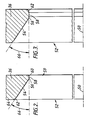
- Figure 2 shows the die 36 in greater detail. It has a central die axis 50 passing through the mid-point of the die and normal to the plane of the die.
- the die is usually of steel but may be of cast iron or sintered polyterafluoroethylene and has a circular opening 52 forming an entry 54, a throat 58 and an exit 59, all of which are symmetrical with respect to the central longitudinal die axis 50.
- the entry 54 preferably makes an angle between 10 degrees and 15 degrees with the axis 50: in this example it is 12.5 degrees to the axis 50, the angle being shown at 66.
- the throat 58 is defined by the merger, in a continuous curve, of a radius 56 joining the entry 54 and by a radius 60 joining the exit 59.
- the entry 54 is joined by a radius 62 to merge with the vertical, planar face 64 of the die 36.
- the liner 30 is polyethylene of the grade known as PE-A supplied by DuPont (UK) Ltd., and made from DuPont Company Ltd. material sold under the Registered Trade Mark "Aldyl A”.
- the liner 30 has an external diameter of nominally 215 millimetres and a Standard Dimension Ratio of 26.
- the liner is used to line a spun cast grey iron main having a nominal bore of 8 inches (203.2 mm). Owing to variations in the wall thickness of the cast iron, the bore may vary between 209.8 mm and 218.4 mm. Accordingly, the die 36 has a diameter of 188.7 mm at its throat 58. The diameter of the liner at exit from the die is 197.5 mm.
- the throat diameter of an unlubricated die is preferably between 8-12% less than the original liner diameter 30, to keep the pulling load below half yield. However, the throat may be relatively smaller, for example 18% less when lining a 4-inch pit cast iron main with 110 mm liner of polyethylene.
- the pipe 10 may be of 4 inches (101.6 mm) up to 12 inches (304.8 mm) or more in internal diameter.
- the typical sizes are 6 inch (152.4 mm); 8 inch (203.2 mm); 10 inch (254 mm); and 12 inch.
- the minimum internal diameter of such cast iron pipes varies greatly.
- a range of dies to suit both the size and the type of pipe being lined.
- a 285 mm die is used for Class "B” and Class "C” pipe and a 278 mm die is used for Class "D” pipe.
- Such pipes are of spun, cast grey iron. Class “B” is commonly used for gas pipes and Class "D” for water pipes.
- the die 36 has a short cylindrical section forming the throat 58.
- the cylindrical section is 8 mm long and is joined by a radius at 56 to the entry 54 and by a radius at 62 to the exit 59 of the die 36.
- the throat 58 has a diameter of 188.7 mm.
- the exit 59 in both cases, is such as to minimise the area of the die 36 engaged by the liner 30 as it leaves the die 36.
- the exit 59 has a radius such that the throat 58 is the last point at which the die 36 contacts the liner 30.
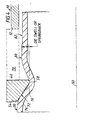
- Figure 4 shows the behaviour of the liner 30 as it passes through the swaging die 40.
- the die 40 is at the alternative position shown in Figure 1.
- the die 40 can be located relative to the end 12 of the pipe 10 by locating members, one of which is shown at 70. However, the behaviour would be exactly the same if the die were at the position 36 shown in Figure 1.
- the liner 30 engages the die 40 at its entry 54 at the area 72, the liner wall 74 having bent inwardly to do so. Continuing to bend inwardly, the wall 74 leaves the entry 54 in the zone 76. Then, the wall bends continuously through its minimum diameter as it passes the throat 58. The liner then undergoes "die swell” until it reaches its maximum diameter at 80. After the point 80 the wall 74 bends inwards very slightly to the diameter shown at 82.
- Figure 4 also shows the end 12 of the pipe 10 into which the liner 30 is pulled by the tension in the cable 34.
- die swell The increase in diameter which the liner 30 undergoes after passing through the die 40 is known as "die swell".
- the exact amount of die swell is the difference between the diameter at 80 and the minimum or throat diameter at 58 of the die 40. It is more practical to measure the liner diameter at a greater distance from the die 40 i.e. to measure the diameter 82 and call die swell the difference between the diameter at 82 and the minimum or throat diameter at 58 of the die 40.
- the die swell has to be taken account of in choosing the parameters of the present invention.
- it is the diameter of the liner, including die swell, which is chosen to be less than the minimum bore diameter of the pipe 10.
- the pulling force is kept preferably at about half the yield strength of the liner, and the die 36 or 40 is dimensioned to ensure that the die swell is just at the correct value.
- the choice is made to allow the liner 30 to be pulled into the pipe 10 with a "window" to allow the pull to be stopped for say, for example, 30 minutes if necessary.
- the die acts as means of reducing the liner diameter through its profile and frictional resistance. Work on the liner is primarily bending. The liner first makes contact with the die entry, the liner must then break away from this surface to enable further bending to take place as it passes through the die throat. The liner finally bends to its final diameter on the exit side of the die as it comes under the influence of the applied load. The complex bending stresses experienced by the liner are felt to be the main feature contributing to the performance of the invention. Throughout its passage through the die the liner remains circular on any plane, and no plastic flow occurs.
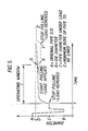
- Figure 5 shows the time after the release of load plotted along the axis of abscissas and the diameter of the liner 30 plotted along the axis of ordinates.
- the liner 30 has a diameter represented as A.
- A the diameter
- B the diameter
- C the diameter
- E the diameter
- the diameter at E represents the minimum internal diameter of the pipe 10.
- Diameter 82 (in Figure 4) is dependent upon the die throat diameter B and the load in pulling the liner through the die. If the load was very small then the diameter 82 would be very similar to the diameter D.
- the ideal situation is one which produces a maximum clearance between liner and pipe internal wall under a load which is below half yield in the material of the liner. On releasing this load a controlled recovery takes place allowing the liner gradually to come into contact with the pipe internal wall.
- the resultant liner is tapered with a minimum diameter at the winch end and a maximum diameter at the die end. Longitudinal strains along the liner also vary. The resultant liner following pulling into the pipe without the application of heat is of a fairly uniform diameter along its length and is of uniform longitudinal strain. The difference in performance between the two methods can be explained by creep of the liner whilst under load at the higher temperature.
- the liner recovery should not be so great to cause the liner to expand against the pipe internal wall. In practise it has been found that the majority of faults can be rectified within 30 minutes. It is preferred therefore that the die design and the loads required will produce a window of 30 minutes before the liner engages the pipe internal wall around its full circumference.
- the liner is normally passed through the die without preheating.
- the equipment that would be used for example, is the heater shown in our GB patent application publication No. 2186340 A.
- the overall towing force can be reduced by the use of a liner pushing device positioned preferably after the die, especially where the liner is 268mm or 315 mm and above.
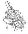
- Figure 6 shows an example of such a device. It consists of a support frame 100 secured to the die or the die support frame.
- the frame 100 supports a carriage 102 running on rollers 104 and movable backwards and forwards by hydraulic cylinder 106.
- the carriage 102 supports a fixed lower jaw 108 and two movable jaws 110.
- the jaws 110 are carried by arms 112 pivoted on pins 114 and movable by a hydraulic cylinder 116.
- the carriage 102 is shown in the position in which, in use, the jaws 108, 110 are released from the liner 30.
- the cylinders 106 next retract, the jaws 108, 110 are closed by the cylinder 116 and the cylinder 106 extend again to push the liner 30 towards the pipe 10 in the direction of the arrow shown.
- FIG. 7 An alternative position for the pushing device is as shown in Figure 7 downstream of the die 36 or 40.
- the die is at position 40. It is supported on the end of the existing cast iron or other pipe 10 by struts 150. Pushing hydraulic cylinders are shown at 152. The gripping jaws are shown at 154. The hydraulic cylinder for actuating the jaws is not shown, for simplicity.
- the die 40 is split, for example into two halves, and can be removed from the liner 30 when pulling through the pipe 10 is completed.
- an approved lubricant can be used to reduce friction between the liner and the pipe.
- the lubricant can be water or a water-based lubricant, for example.
- the lubricant may be water or a water-based lubricant.
- a non-aqueous lubricant such as CASTROL D416 (CASTROL is a Registered Trade Mark) or monoethylene glycol, for example.
- the lubricant is applied to the die inner surface where it is wiped by the liner 30. Alternatively, it is applied to the surface of the liner 30.
- the lubricant may be projected from an annulus surrounding the liner 30.
- jets or sprays of liquid lubricant may impinge on the liner 30.
- the ring may have an inwardly projecting brush or swab which bears on the liner 30.
- the liner may be preferable to lubricate the liner as it enters the pipe and not on the entry to the die.
- the die at its internal swaging surface may be machined down to N7 or N6 finish at least, for example.
- the finish is N5 or N4 or lower.
- the liner was grade X, commonly known as PE-X in each case.
- the third manufacturer of the resin liner was Stewarts & Lloyds Plastics, a division of Victaulic plc.
- the expected bore was less than the liner diameter after 30 minutes. Therefore, less than 30 minutes would have been available for any repair involving a halt in pulling and removal of load.
- a suitably larger die would have been used.
- a range of dies has been made and with proper gauge-pigging before lining commences, the true expected bore can be anticipated and a die chosen to give a 30 minute window as explained.
- the pipe was 10-inch.
- the liner diameter after 30 minute (262 mm) was found to be less than the expected bore (266 mm) of the pipe. A 30 minute window would have been a feasible option.
Landscapes
- Engineering & Computer Science (AREA)
- General Engineering & Computer Science (AREA)
- Mechanical Engineering (AREA)
- Manufacturing & Machinery (AREA)
- Lining Or Joining Of Plastics Or The Like (AREA)
- Application Of Or Painting With Fluid Materials (AREA)
- Extrusion Moulding Of Plastics Or The Like (AREA)
Abstract
Description
- The invention relates to a method of and apparatus for lining a buried pipe with a polymer liner.
- The method is applicable, for example, to lining a buried gas, water or sewage pipe. Such pipes are made of cast iron or steel or particularly, in the case of water, of asbestos cement or concrete for example, and particularly cast iron pipes may be lined with bitumen or concrete.
- In British Gas patent application publication No. 2186340 there is described a method applicable to buried gas, water or sewage pipes in which a length of synthetic resin liner is heated, pulled through a die and through the pipe to be lined and pressurised to cause it to expand into engagement with the internal wall of the pipe.
- In United States patent No. 3 462 825 (Pope et al) there is described a method applicable to the lining of flexible or rigid pipes in the factory by pulling a liner through a die and through the pipe and then releasing the liner pipe, whereupon the liner pipe expends into tight engagement with the internal wall of the pipe. The pipe was of relatively small diameter, having an inside diameter of 2.06 inches (51.5 millimeters) and the liner pipe had an outside diameter of 2.3 inches (57.5 mm). The liner pipe was relatively thin, having a wall thickness of 0.07 inch (1.75 mm) giving a Standard Dimension Ratio (SDR) of 33. The liner pipe was of fluorocarbon. In general, the outside diameter of the liner pipe was 10 to 15% greater than the inside diameter of the pipe to be lined.
- In British patent specification No. 807 413 (Tubovit Societa per Azioni) there is described a method applicable to the lining of metal pipes in the factory by pulling a heated liner pipe through a die and through a pipe to be lined, releasing the liner pipe, and heating the liner pipe. The die diameter is the same as the pipe to be lined or very slightly less. The liner is of polyvinyl chloride very slightly larger than the pipe to be lined and is 3mm thick or less. The liner is heated before or during the die reduction to a temperature at which it is relatively soft and the force used to pull it through the pipe is only relatively low.
- In GB 2186340 such die swell as does occur after the main die is eliminated by the effect of the second die which makesthe diameter of the throat, in each case, the diameter which goes into the pipe. In US 3 462 825 and GB 807 413, no die swell is shown and the diameter which goes into the pipe is the diameter of the throat. Die swell is the increase in diameter which the liner undergoes, according to the present invention, after passing through the die.
- A method of lining a buried pipe with a polymer liner, according to the invention, comprises pulling a length of liner through a die without causing yielding and to reduce its diameter with longitudinal extension, and through the pipe and on removal of the pulling load allowing the liner to revert to at least the minimum internal diameter of the pipe, and the die having a central, longitudinal die axis and comprising an entry, a throat and an exit which are symmetrical about said axis, the entry decreasing in diameter towards said throat and the exit increasing in diameter away from said throat, the liner having a maximum diameter before the die, a minimum diameter in the die and an intermediate diameter after the die, the force of pulling being such as partially to restrain die swell of the liner after its emergence from the throat, the liner bending inwards before first contacting the die at the entry, then leaving the entry before continuously bending through its minimum diameter as it passes the throat, and then undergoing die swell resulting in said intermediate diameter, which enters the pipe.
- The throat may be defined by the merger, in a continuous curve, of a radius joining the entry and a radius joining the exit.
- Alternatively, the throat may comprise a short cylindrical section not more than one centimetre in length which is joined by a radius to the entry and joined by a radius to the exit.
- Preferably, the entry makes an angle of 12.5 degrees with the die axis.
- Apparatus, according to the invention, for lining a pipe with a polymer liner comprises a die, means for anchoring the die in front of the pipe, pulling means, and means for anchoring the pulling means after the pipe, the die having a central longitudinal die axis and comprising an entry, a throat and an exit which are symmetrical about said axis, the entry decreasing towards said throat and the exit increasing in diameter away from said throat, the liner having a maximum diameter before the die, a minimum diameter in the die and an intermediate diameter after the die.
- The throat may be defined by the merger, in a continuous curve, of a radius joining the entry and a radius joining the exit.
- Alternatively, the throat may comprise a short, hollow cylindrical section parallel to the die axis of not more than one centimetre in length which is joined by a radius to the entry and joined by a radius to the exit.
- One method of lining a buried pipe will now be described by way of example with reference to the accompanying drawings, in which :
- Figure 1 is a vertical section through the ground showing the pipe to be lined and showing a liner pipe in the course of being pulled through the pipe to be lined;
- Figure 2 is an enlarged vertical part-section through a die;
- Figure 3 is an enlarged vertical part-section through a modified die;
- Figure 4 is an enlarged vertical part-section through the die and through the liner pipe as it is passing through the die;
- Figure 5 is a graph showing diameter plotted against time for the liner pipe as it passes through the die;
- Figure 6 is an isometric view of a pushing device in position for use adjacent the die; and
- Figure 7 is a vertical section through the die shown supported by the entry end of the pipe to be lined together with pushing means.
- From now on, the liner pipe will be referred to as "the liner" and the pipe to be lined will be referred to as "the pipe".
- Figure 1 shows the buried
pipe 10, which in this case may be for example a cast-iron gas main, with itsends excavations excavations - The
liner 30 is made of polyethylene and is pulled by awinch 32 andcable 34 through aswaging die 36 and through thepipe 10. Theliner 30 after emerging from thedie 36 is guided by aroller 38 to facilitate entry into theend 12 of thepipe 10. The die 36 is secured by members (not shown) driven into the ground. In another alternative position, the die 40 is supported by direct engagement with theend 12 of thepipe 10, or with members engaging theend 12. Thewinch 32 also has to be secured by members (not shown) driven into the ground, or from the end of thepipe 14. - Prior to the operations shown in Figure 1, the pipe was cleaned and checked for internal size by suitable pigs passed through the pipe. At the same time, any protrusions were removed from within the pipe. The liner was made up of lengths of liner above ground. The lengths of liner were joined end to end by butt fusion and the external bead at each fusion joint was removed or directly inserted from a coil of liner (this being the case in sizes up to 180 mm, for example). A pulling cone was attached to the leading end of the liner. The
cable 34 was attached to the end of a stiff rod and the rod was pushed through thepipe 10 from theend 14 to theend 12 until the cable end (at the trailing end of the rod) emerged at theend 12. Thecable 34 was disconnected and fed through thedie 36 and attached to the cone on the liner. Thewinch 32 was then operated to draw the liner through thedie 36, with the longitudinal extension of less than 10%, preferably 8%. - The operator of the winch keeps the winch turning at a constant rate, or nearly so. The rate of advance of the
liner 30 may for example be 3 metres per minute. - When pulling is completed, the liner is allowed to revert at least to the minimum internal diameter of the pipe. The liner is cut leaving sufficient pipe to enable a suitable connection to be effected. Where the die
position 40 is used, a split die is essential. Thewinch cable 34 is removed from theliner 30 which is then cut to allow sufficient length to accomodate contraction as the liner reverts. - It is a particular advantage of using the present method that the length of
pipe 10 can be lined even where the pulling has to be interrupted for any reason. For example, the winch may fail and require attention. This means that the pulling tension in thecable 34 is removed, with theliner 30 at rest part-way through the pipe, while a repair is effected for example. Then, the pulling tension is again applied and theliner 30 again advances through thepipe 10. The period required for such an emergency can vary but for the lining of buried gas pipes it is considered that a period of 30 minutes should be provided, for example. - During such a break in pulling, the liner pipe increases in diameter. If the diameter of the liner increases so that it approaches the internal pipe wall then frictional forces on restarting the operation of pulling are so high as to prevent the pipe moving without yielding.
- Figure 2 shows the die 36 in greater detail. It has a
central die axis 50 passing through the mid-point of the die and normal to the plane of the die. The die is usually of steel but may be of cast iron or sintered polyterafluoroethylene and has acircular opening 52 forming anentry 54, athroat 58 and anexit 59, all of which are symmetrical with respect to the centrallongitudinal die axis 50. Theentry 54 preferably makes an angle between 10 degrees and 15 degrees with the axis 50: in this example it is 12.5 degrees to theaxis 50, the angle being shown at 66. Thethroat 58 is defined by the merger, in a continuous curve, of aradius 56 joining theentry 54 and by aradius 60 joining theexit 59. Theentry 54 is joined by aradius 62 to merge with the vertical,planar face 64 of thedie 36. - For the present example, the
liner 30 is polyethylene of the grade known as PE-A supplied by DuPont (UK) Ltd., and made from DuPont Company Ltd. material sold under the Registered Trade Mark "Aldyl A". Theliner 30 has an external diameter of nominally 215 millimetres and a Standard Dimension Ratio of 26. The liner is used to line a spun cast grey iron main having a nominal bore of 8 inches (203.2 mm). Owing to variations in the wall thickness of the cast iron, the bore may vary between 209.8 mm and 218.4 mm. Accordingly, thedie 36 has a diameter of 188.7 mm at itsthroat 58. The diameter of the liner at exit from the die is 197.5 mm. On release of the load the pipe diameter increases to 209.4 mm after 1 hour and 210.9 mm after 24 hours. The throat diameter of an unlubricated die is preferably between 8-12% less than theoriginal liner diameter 30, to keep the pulling load below half yield. However, the throat may be relatively smaller, for example 18% less when lining a 4-inch pit cast iron main with 110 mm liner of polyethylene. - The
pipe 10 may be of 4 inches (101.6 mm) up to 12 inches (304.8 mm) or more in internal diameter. For gas pipe, the typical sizes are 6 inch (152.4 mm); 8 inch (203.2 mm); 10 inch (254 mm); and 12 inch. As stated above, the minimum internal diameter of such cast iron pipes varies greatly. In order to reduce the problem it is convenient to have available a range of dies to suit both the size and the type of pipe being lined. For example, on 12 pipe, a 285 mm die is used for Class "B" and Class "C" pipe and a 278 mm die is used for Class "D" pipe. Such pipes are of spun, cast grey iron. Class "B" is commonly used for gas pipes and Class "D" for water pipes. - In a modification shown in Figure 3, the
die 36 has a short cylindrical section forming thethroat 58. Typically, for example, the cylindrical section is 8 mm long and is joined by a radius at 56 to theentry 54 and by a radius at 62 to theexit 59 of thedie 36. Thethroat 58 has a diameter of 188.7 mm. - The
exit 59 in both cases, is such as to minimise the area of the die 36 engaged by theliner 30 as it leaves thedie 36. Theexit 59 has a radius such that thethroat 58 is the last point at which the die 36 contacts theliner 30. - Figure 4 shows the behaviour of the
liner 30 as it passes through the swaging die 40. For simplicity it is assumed thedie 40 is at the alternative position shown in Figure 1. The die 40 can be located relative to theend 12 of thepipe 10 by locating members, one of which is shown at 70. However, the behaviour would be exactly the same if the die were at theposition 36 shown in Figure 1. - As is shown in Figure 4, the
liner 30 engages the die 40 at itsentry 54 at thearea 72, theliner wall 74 having bent inwardly to do so. Continuing to bend inwardly, thewall 74 leaves theentry 54 in thezone 76. Then, the wall bends continuously through its minimum diameter as it passes thethroat 58. The liner then undergoes "die swell" until it reaches its maximum diameter at 80. After thepoint 80 thewall 74 bends inwards very slightly to the diameter shown at 82. - Figure 4 also shows the
end 12 of thepipe 10 into which theliner 30 is pulled by the tension in thecable 34. - The increase in diameter which the
liner 30 undergoes after passing through thedie 40 is known as "die swell". The exact amount of die swell is the difference between the diameter at 80 and the minimum or throat diameter at 58 of thedie 40. It is more practical to measure the liner diameter at a greater distance from the die 40 i.e. to measure thediameter 82 and call die swell the difference between the diameter at 82 and the minimum or throat diameter at 58 of thedie 40. - The die swell has to be taken account of in choosing the parameters of the present invention. Thus, in this invention, it is the diameter of the liner, including die swell, which is chosen to be less than the minimum bore diameter of the
pipe 10. - The pulling force is kept preferably at about half the yield strength of the liner, and the die 36 or 40 is dimensioned to ensure that the die swell is just at the correct value. Preferably, the choice is made to allow the
liner 30 to be pulled into thepipe 10 with a "window" to allow the pull to be stopped for say, for example, 30 minutes if necessary. - The die acts as means of reducing the liner diameter through its profile and frictional resistance. Work on the liner is primarily bending. The liner first makes contact with the die entry, the liner must then break away from this surface to enable further bending to take place as it passes through the die throat. The liner finally bends to its final diameter on the exit side of the die as it comes under the influence of the applied load. The complex bending stresses experienced by the liner are felt to be the main feature contributing to the performance of the invention. Throughout its passage through the die the liner remains circular on any plane, and no plastic flow occurs.
- Figure 5 shows the time after the release of load plotted along the axis of abscissas and the diameter of the
liner 30 plotted along the axis of ordinates. Theliner 30 has a diameter represented as A. As theliner 30 passes through theentry 54 of the die 36 or 40, the diameter decreases to the value B, which corresponds to thethroat 58. Beyond thethroat 58 the diameter increases to the value C, which corresponds to thediameter 80 in Figure 4. The slight decrease in diameter to 82 is not shown in Figure 5. At time equal to "t", the load is removed. The diameter increases very rapidly to the diameter D and then much more slowly, over a period of some 24 hours, to the value E. The diameter at E represents the minimum internal diameter of thepipe 10. - Diameter 82 (in Figure 4) is dependent upon the die throat diameter B and the load in pulling the liner through the die. If the load was very small then the
diameter 82 would be very similar to the diameter D. - The ideal situation is one which produces a maximum clearance between liner and pipe internal wall under a load which is below half yield in the material of the liner. On releasing this load a controlled recovery takes place allowing the liner gradually to come into contact with the pipe internal wall.
- If the liner is preheated before pulling into the pipe, the resultant liner is tapered with a minimum diameter at the winch end and a maximum diameter at the die end. Longitudinal strains along the liner also vary. The resultant liner following pulling into the pipe without the application of heat is of a fairly uniform diameter along its length and is of uniform longitudinal strain. The difference in performance between the two methods can be explained by creep of the liner whilst under load at the higher temperature.
- If the pull has to be stopped and the load removed for any reason, e.g. winch or cable failure, the liner recovery should not be so great to cause the liner to expand against the pipe internal wall. In practise it has been found that the majority of faults can be rectified within 30 minutes. It is preferred therefore that the die design and the loads required will produce a window of 30 minutes before the liner engages the pipe internal wall around its full circumference.
- On restarting the pulling operation, the leading end will not reduce to its original diameter C. The reduction obtained is only due to the Poisson's ratio of the material. This is shown in Figure 5. The broken line between X and Y shows the characteristic. The continued broken line Y to Z shows the characteristic for the reversion of the liner following a halt to pulling after a repair. Clearly, the point X is the latest possible to resume pulling. The clearance shown at G was the smallest permissible to avoid high friction with the pipe internal wall. The material passing through the die on re-starting the pull is at diameter C. On completion of the operation the pipe recovers to the same dimension, i.e. the pipe internal wall, throughout its whole length.
- The liner is normally passed through the die without preheating. When the weather is cold, it may be necessary to pre-warm the liner to bring its temperature up to for example 30oC. In that case, the equipment that would be used, for example, is the heater shown in our GB patent application publication No. 2186340 A.
- The method enables over 90% of the gas carrying capacity of the pipe to be retained when the pipe is lined as explained herein. For example, using liner of SDR = 26 for lining gas pipe, tests have shown that up to 93.5% of the gas carrying capacity of the gas pipe can be used for pipe up to 315mm.
- The overall towing force can be reduced by the use of a liner pushing device positioned preferably after the die, especially where the liner is 268mm or 315 mm and above. Figure 6 shows an example of such a device. It consists of a
support frame 100 secured to the die or the die support frame. Theframe 100 supports acarriage 102 running onrollers 104 and movable backwards and forwards byhydraulic cylinder 106. Thecarriage 102 supports a fixedlower jaw 108 and twomovable jaws 110. Thejaws 110 are carried byarms 112 pivoted onpins 114 and movable by ahydraulic cylinder 116. - The
carriage 102 is shown in the position in which, in use, thejaws liner 30. Thecylinders 106 next retract, thejaws cylinder 116 and thecylinder 106 extend again to push theliner 30 towards thepipe 10 in the direction of the arrow shown. - An alternative position for the pushing device is as shown in Figure 7 downstream of the die 36 or 40. In Figure 7 the die is at
position 40. It is supported on the end of the existing cast iron orother pipe 10 bystruts 150. Pushing hydraulic cylinders are shown at 152. The gripping jaws are shown at 154. The hydraulic cylinder for actuating the jaws is not shown, for simplicity. Thedie 40 is split, for example into two halves, and can be removed from theliner 30 when pulling through thepipe 10 is completed. - Whether the pushing device is used or not, an approved lubricant can be used to reduce friction between the liner and the pipe. The lubricant can be water or a water-based lubricant, for example.
- It may be preferable to use lubricant at the die to reduce friction. The lubricant may be water or a water-based lubricant. Alternatively, a non-aqueous lubricant, such as CASTROL D416 (CASTROL is a Registered Trade Mark) or monoethylene glycol, for example. The lubricant is applied to the die inner surface where it is wiped by the
liner 30. Alternatively, it is applied to the surface of theliner 30. - For example, the lubricant may be projected from an annulus surrounding the
liner 30. For example, jets or sprays of liquid lubricant may impinge on theliner 30. Alternatively, the ring may have an inwardly projecting brush or swab which bears on theliner 30. - Depending upon the load derived by pulling the liner through the die it may be preferable to lubricate the liner as it enters the pipe and not on the entry to the die.
- The die at its internal swaging surface may be machined down to N7 or N6 finish at least, for example. Preferably, the finish is N5 or N4 or lower.
- Three examples below of lining gas pipes with a polyethylene liner are given below. The liner was grade X, commonly known as PE-X in each case. The third manufacturer of the resin liner was Stewarts & Lloyds Plastics, a division of Victaulic plc. In the first two examples, the expected bore was less than the liner diameter after 30 minutes. Therefore, less than 30 minutes would have been available for any repair involving a halt in pulling and removal of load. Of course, had the expected bore been properly anticipated in use, a suitably larger die would have been used. In practise, now, a range of dies has been made and with proper gauge-pigging before lining commences, the true expected bore can be anticipated and a die chosen to give a 30 minute window as explained. In the third example the pipe was 10-inch. The liner diameter after 30 minute (262 mm) was found to be less than the expected bore (266 mm) of the pipe. A 30 minute window would have been a feasible option.
- The purpose of giving these examples is to show that the invention provides for controlled reversion to the internal wall of the pipe. There is no need for heating or pressurisation to achieve a liner tight against the internal wall. With care, the true anticipated expected bore can be known beforehand and a die chosen to give the 30 minute window to allow repairs involving stoppage of pulling.
initial diameter of liner 110 mm 110 mm 268 mm die diameter 95 mm 90 mm 242 mm pipe diameter: expected bore 107 mm 102 mm 266 mm material of liner PE-X PE-X PE-X manufacturer of liner UPONOR WAVIN Stewarts & Lloyds SDR of liner 26 17 26 load of pulling 1.0 Tonne 1.4 Tonne 3.75Tonne speed of pulling 2m/minute 2m/minute 3m/minute diameter of liner: including die swell 98mm 94mm 252mm average diameter of liner: after release of load 102mm 100mm 258mm after 30 minutes 107mm 103mm 262mm after 1 hour 107mm 103mm 263mm after 24 hours 109mm 105mm tight fit in pipe
Claims (23)
Priority Applications (1)
| Application Number | Priority Date | Filing Date | Title |
|---|---|---|---|
| AT89304599T ATE82057T1 (en) | 1988-05-09 | 1989-05-08 | METHOD AND APPARATUS FOR LINING A BURIED PIPE WITH A POLYMERIC LAYER. |
Applications Claiming Priority (12)
| Application Number | Priority Date | Filing Date | Title |
|---|---|---|---|
| GB8810891 | 1988-05-09 | ||
| GB8810893A GB2218485B (en) | 1988-05-09 | 1988-05-09 | Pipelines |
| GB8810894A GB2218486B (en) | 1988-05-09 | 1988-05-09 | Piplines. |
| GB8810897A GB2218489B (en) | 1988-05-09 | 1988-05-09 | Pipeline liner pipes and liner pipe swaging dies |
| GB8810892A GB2218484B (en) | 1988-05-09 | 1988-05-09 | Pipelines |
| GB8810894 | 1988-05-09 | ||
| GB8810893 | 1988-05-09 | ||
| GB8810897 | 1988-05-09 | ||
| GB8810891A GB2218370B (en) | 1988-05-09 | 1988-05-09 | Pipelining and liner pipe swaging dies. |
| GB8810892 | 1988-05-09 | ||
| GB8819063A GB2221741B (en) | 1988-08-11 | 1988-08-11 | Pipelining and liner pipe swaging dies |
| GB8819063 | 1988-08-11 |
Publications (2)
| Publication Number | Publication Date |
|---|---|
| EP0341941A1 true EP0341941A1 (en) | 1989-11-15 |
| EP0341941B1 EP0341941B1 (en) | 1992-11-04 |
Family
ID=27547005
Family Applications (1)
| Application Number | Title | Priority Date | Filing Date |
|---|---|---|---|
| EP89304599A Expired - Lifetime EP0341941B1 (en) | 1988-05-09 | 1989-05-08 | Method and apparatus for lining a buried pipe with a polymer liner |
Country Status (19)
| Country | Link |
|---|---|
| US (1) | US5048174A (en) |
| EP (1) | EP0341941B1 (en) |
| JP (1) | JPH072380B2 (en) |
| KR (1) | KR930006025B1 (en) |
| AU (1) | AU594008B2 (en) |
| CA (1) | CA1314201C (en) |
| DE (1) | DE68903357T2 (en) |
| DK (1) | DK173523B1 (en) |
| ES (1) | ES2036801T3 (en) |
| FI (1) | FI90133C (en) |
| GB (1) | GB2218491A (en) |
| GR (1) | GR3006309T3 (en) |
| HK (1) | HK79293A (en) |
| HU (1) | HU215739B (en) |
| IL (1) | IL90251A0 (en) |
| NO (1) | NO180654C (en) |
| NZ (1) | NZ228962A (en) |
| PL (1) | PL161728B1 (en) |
| PT (1) | PT90515B (en) |
Cited By (7)
| Publication number | Priority date | Publication date | Assignee | Title |
|---|---|---|---|---|
| WO1995027168A1 (en) * | 1994-03-31 | 1995-10-12 | British Gas Plc | Method and apparatus for lining a pipe with a polymer liner |
| WO1998050724A1 (en) * | 1997-05-08 | 1998-11-12 | Bg Plc | Pipe lining |
| WO1999064222A1 (en) * | 1998-06-10 | 1999-12-16 | Lattice Intellectual Property Ltd. | Pipe lining |
| WO2008000474A2 (en) | 2006-06-30 | 2008-01-03 | Tracto-Technik Gmbh & Co. Kg | Device and method for easily inserting a long plastic tube into a duct via a shaft |
| WO2011045567A1 (en) | 2009-10-13 | 2011-04-21 | Pioneer Lining Technology Limited | Lined pipes with insulation |
| US10039285B2 (en) | 2012-05-02 | 2018-08-07 | Brigham Young University | Ceragenin particulate materials and methods for making same |
| US10823324B2 (en) | 2014-10-29 | 2020-11-03 | Radius Systems Limited | Method of lining a tubular structure |
Families Citing this family (21)
| Publication number | Priority date | Publication date | Assignee | Title |
|---|---|---|---|---|
| GB8626354D0 (en) * | 1986-11-04 | 1986-12-03 | Du Pont Canada | In-situ method for lining pipe |
| GB2218486B (en) * | 1988-05-09 | 1993-02-03 | British Gas Plc | Piplines. |
| US6240612B1 (en) * | 1988-05-09 | 2001-06-05 | British Gas Plc | Method for the lining of existing pipes |
| AU4328589A (en) * | 1988-09-13 | 1990-04-02 | North West Water Authority | Methods and apparatus for use in pipe lining |
| DE69113303T2 (en) * | 1990-03-26 | 1996-05-15 | Tsutsunaka Plastic Kogyo K K | Polyvinyl chloride pipe for lining the inside of pipes. |
| JPH07115410B2 (en) * | 1990-06-28 | 1995-12-13 | 住友金属工業株式会社 | Inner surface lining method using polyolefin resin tube |
| WO1992012844A1 (en) * | 1991-01-22 | 1992-08-06 | Pipe Rehab International, Inc. | Variable angular insertion method for lining tubular members |
| GB9102951D0 (en) * | 1991-02-12 | 1991-03-27 | North West Water Ltd | Improvements in or relating to pipe handling |
| ES2131430B1 (en) * | 1994-03-11 | 2000-02-01 | Pipelining Products Inc | METHOD FOR RE-COATING PRE-EXISTING PIPES, DEFORMING APPARATUS AND CORRESPONDING METHOD AND TUBE INSERT USED. |
| US5525049A (en) * | 1994-03-11 | 1996-06-11 | Paletta; Stephen | Polymeric pipe deformer |
| US6403181B1 (en) | 1995-07-03 | 2002-06-11 | Mobil Oil Corporation | Premium pipe resins |
| US5992467A (en) * | 1996-12-30 | 1999-11-30 | Roach; Max Jerry | Liner reduction system using pressurized dies and apparatus therefor |
| NL1016976C2 (en) * | 2000-12-22 | 2002-06-25 | Afa Polytek Bv | Method for tightly fitting a flexible element and assembly for use in that method in a tube. |
| JP2007263247A (en) * | 2006-03-29 | 2007-10-11 | Sekisui Chem Co Ltd | Pulling device for existing pipe lining pipe member |
| CA2697005C (en) * | 2006-08-21 | 2013-05-28 | Western Slope Utilities, Inc. | Systems and methods for pipeline rehabilitation installation |
| DE102009012613B4 (en) * | 2009-03-11 | 2014-02-06 | Tracto-Technik Gmbh & Co. Kg | Method and device for introducing a pipe into a hole in the ground |
| DE102010004097B4 (en) * | 2010-01-07 | 2019-06-19 | Tracto-Technik Gmbh & Co. Kg | Method for rehabilitating an old pipe and system for carrying out such a method |
| US9377149B2 (en) | 2013-03-14 | 2016-06-28 | SAK Construction, LLC | Systems and apparatus for inhibiting a compressed pipe liner from retreating into a host pipe |
| US9322502B2 (en) | 2013-03-14 | 2016-04-26 | SAK Construction, LLC | Device and system for pulling a compressed pipe liner into a host pipe |
| US10234350B1 (en) * | 2016-10-18 | 2019-03-19 | United Services Automobile Association (Usaa) | Appliance hose ballooning/failure detector loop |
| US11920721B2 (en) * | 2019-08-13 | 2024-03-05 | Andrew J. Mayer | Apparatus and method for in-situ fabrication of bi-layer composite pipe by deformation manufacture of compression-fit, shape memory polymer pipe (SMPP) mechanically united with host pipe |
Citations (3)
| Publication number | Priority date | Publication date | Assignee | Title |
|---|---|---|---|---|
| US3462825A (en) * | 1967-07-11 | 1969-08-26 | Dore Co John L | Method of lining tubular members |
| GB2186340A (en) * | 1986-02-10 | 1987-08-12 | British Gas Plc | Pipe lining and closure therefor |
| EP0266951A2 (en) * | 1986-11-04 | 1988-05-11 | Du Pont Canada Inc. | In-situ method for lining pipe with polymeric liner |
Family Cites Families (8)
| Publication number | Priority date | Publication date | Assignee | Title |
|---|---|---|---|---|
| US2110783A (en) * | 1936-04-25 | 1938-03-08 | Albert R Teare | Resilient bushing and method and apparatus for making same |
| NL162275B (en) * | 1950-07-22 | 1900-01-01 | Texas Instruments Inc | OPTO-ELECTRONIC GEARBOX. |
| GB777927A (en) * | 1953-07-14 | 1957-07-03 | Stewarts & Lloyds Ltd | A process and apparatus for the profiling of solid and tubular sections |
| BE531382A (en) * | 1953-08-25 | 1900-01-01 | ||
| BE549046A (en) * | 1955-06-27 | 1900-01-01 | ||
| FR2096557A1 (en) * | 1970-06-29 | 1972-02-18 | Dow Chemical Co | Plastics lined pipes prodn - by introduction of compressed lining and allowing the lining to expand to grip the pipe wall |
| US4504171A (en) * | 1983-09-02 | 1985-03-12 | Getty Synthetic Fuels, Inc. | Liner installation tool and method |
| GB2218486B (en) * | 1988-05-09 | 1993-02-03 | British Gas Plc | Piplines. |
-
1989
- 1989-05-03 NZ NZ228962A patent/NZ228962A/en unknown
- 1989-05-04 CA CA000598710A patent/CA1314201C/en not_active Expired - Lifetime
- 1989-05-08 ES ES198989304599T patent/ES2036801T3/en not_active Expired - Lifetime
- 1989-05-08 GB GB8910508A patent/GB2218491A/en not_active Withdrawn
- 1989-05-08 EP EP89304599A patent/EP0341941B1/en not_active Expired - Lifetime
- 1989-05-08 AU AU34545/89A patent/AU594008B2/en not_active Expired
- 1989-05-08 DK DK198902246A patent/DK173523B1/en not_active IP Right Cessation
- 1989-05-08 FI FI892196A patent/FI90133C/en not_active IP Right Cessation
- 1989-05-08 DE DE8989304599T patent/DE68903357T2/en not_active Expired - Lifetime
- 1989-05-08 NO NO891878A patent/NO180654C/en not_active IP Right Cessation
- 1989-05-08 HU HU892205A patent/HU215739B/en unknown
- 1989-05-09 IL IL90251A patent/IL90251A0/en not_active IP Right Cessation
- 1989-05-09 KR KR1019890006257A patent/KR930006025B1/en not_active IP Right Cessation
- 1989-05-09 PT PT90515A patent/PT90515B/en not_active IP Right Cessation
- 1989-05-09 PL PL89279341A patent/PL161728B1/en unknown
- 1989-05-09 JP JP1115910A patent/JPH072380B2/en not_active Expired - Fee Related
-
1990
- 1990-04-12 US US07/508,529 patent/US5048174A/en not_active Expired - Lifetime
-
1992
- 1992-11-20 GR GR920402372T patent/GR3006309T3/el unknown
-
1993
- 1993-08-05 HK HK792/93A patent/HK79293A/en not_active IP Right Cessation
Patent Citations (3)
| Publication number | Priority date | Publication date | Assignee | Title |
|---|---|---|---|---|
| US3462825A (en) * | 1967-07-11 | 1969-08-26 | Dore Co John L | Method of lining tubular members |
| GB2186340A (en) * | 1986-02-10 | 1987-08-12 | British Gas Plc | Pipe lining and closure therefor |
| EP0266951A2 (en) * | 1986-11-04 | 1988-05-11 | Du Pont Canada Inc. | In-situ method for lining pipe with polymeric liner |
Cited By (8)
| Publication number | Priority date | Publication date | Assignee | Title |
|---|---|---|---|---|
| WO1995027168A1 (en) * | 1994-03-31 | 1995-10-12 | British Gas Plc | Method and apparatus for lining a pipe with a polymer liner |
| CN1045124C (en) * | 1994-03-31 | 1999-09-15 | 英国气体公司 | Method and apparatus for lining a pipe with a polymer liner |
| WO1998050724A1 (en) * | 1997-05-08 | 1998-11-12 | Bg Plc | Pipe lining |
| WO1999064222A1 (en) * | 1998-06-10 | 1999-12-16 | Lattice Intellectual Property Ltd. | Pipe lining |
| WO2008000474A2 (en) | 2006-06-30 | 2008-01-03 | Tracto-Technik Gmbh & Co. Kg | Device and method for easily inserting a long plastic tube into a duct via a shaft |
| WO2011045567A1 (en) | 2009-10-13 | 2011-04-21 | Pioneer Lining Technology Limited | Lined pipes with insulation |
| US10039285B2 (en) | 2012-05-02 | 2018-08-07 | Brigham Young University | Ceragenin particulate materials and methods for making same |
| US10823324B2 (en) | 2014-10-29 | 2020-11-03 | Radius Systems Limited | Method of lining a tubular structure |
Also Published As
| Publication number | Publication date |
|---|---|
| NZ228962A (en) | 1990-08-28 |
| FI90133C (en) | 1993-12-27 |
| HU215739B (en) | 1999-02-01 |
| KR930006025B1 (en) | 1993-07-01 |
| ES2036801T3 (en) | 1993-06-01 |
| NO891878D0 (en) | 1989-05-08 |
| GB8910508D0 (en) | 1989-06-21 |
| JPH072380B2 (en) | 1995-01-18 |
| GR3006309T3 (en) | 1993-06-21 |
| JPH0216033A (en) | 1990-01-19 |
| IL90251A0 (en) | 1989-12-15 |
| US5048174A (en) | 1991-09-17 |
| PT90515A (en) | 1989-11-30 |
| DK224689A (en) | 1989-11-10 |
| EP0341941B1 (en) | 1992-11-04 |
| NO891878L (en) | 1989-11-10 |
| KR900018585A (en) | 1990-12-22 |
| HUT51746A (en) | 1990-05-28 |
| HK79293A (en) | 1993-08-13 |
| AU3454589A (en) | 1989-11-09 |
| DK224689D0 (en) | 1989-05-08 |
| PL279341A1 (en) | 1990-01-08 |
| PT90515B (en) | 1994-05-31 |
| PL161728B1 (en) | 1993-07-30 |
| NO180654B (en) | 1997-02-10 |
| DE68903357T2 (en) | 1993-04-22 |
| DK173523B1 (en) | 2001-01-29 |
| NO180654C (en) | 1997-05-21 |
| AU594008B2 (en) | 1990-02-22 |
| FI892196A (en) | 1989-11-10 |
| FI892196A0 (en) | 1989-05-08 |
| FI90133B (en) | 1993-09-15 |
| CA1314201C (en) | 1993-03-09 |
| GB2218491A (en) | 1989-11-15 |
| DE68903357D1 (en) | 1992-12-10 |
Similar Documents
| Publication | Publication Date | Title |
|---|---|---|
| EP0341941B1 (en) | Method and apparatus for lining a buried pipe with a polymer liner | |
| EP0097470B1 (en) | A device for removing irregularities in or enlarging an underground duct | |
| US4986951A (en) | Pipe liner process | |
| EP0301697A2 (en) | A method and apparatus for producing a deformed pipe liner of tubular cross-section. | |
| GB2172845A (en) | Method for joining polyolefin pipes by fusion | |
| EP0756687B1 (en) | Method for lining a pipe with a polymer liner | |
| JPH0752249A (en) | Lining device for installed pipe | |
| EP0266951B1 (en) | In-situ method for lining pipe with polymeric liner | |
| WO1990002904A1 (en) | Methods and apparatus for use in pipe lining | |
| US5007767A (en) | Method for joining polyolefin pipes by fusion | |
| US2983366A (en) | Hydraulic devices for removing tubes drawn on a long mandrel | |
| DD295900A5 (en) | METHOD AND DEVICE FOR CLADDING PIPES WITH A POLYMER | |
| JPH11230412A (en) | Regeneration method for existing pipeline | |
| CA2319901C (en) | Method and apparatus for forming bends in thermoplastic pipe | |
| SU1479233A1 (en) | Method of resistance butt welding of pipes | |
| WO1998050724A1 (en) | Pipe lining | |
| GB2160144A (en) | Shaping pipe ends | |
| CN1037765A (en) | Give the method and apparatus of under ground piping addition polymerization compound bushing pipe | |
| JPH04234629A (en) | Method of lining construction of existing pipe | |
| JPH11270745A (en) | Method for regenerating existing pipeline | |
| MXPA96004456A (en) | Method and apparatus for covering a pipe with a polimer coating | |
| MXPA06003701A (en) | Improvements in a machine and process for injecting an inner coating into steel tubes. |
Legal Events
| Date | Code | Title | Description |
|---|---|---|---|
| PUAI | Public reference made under article 153(3) epc to a published international application that has entered the european phase |
Free format text: ORIGINAL CODE: 0009012 |
|
| AK | Designated contracting states |
Kind code of ref document: A1 Designated state(s): AT BE CH DE ES FR GB GR IT LI LU NL SE |
|
| RAP1 | Party data changed (applicant data changed or rights of an application transferred) |
Owner name: BRITISH GAS PLC |
|
| 17P | Request for examination filed |
Effective date: 19891017 |
|
| 17Q | First examination report despatched |
Effective date: 19901219 |
|
| GRAA | (expected) grant |
Free format text: ORIGINAL CODE: 0009210 |
|
| AK | Designated contracting states |
Kind code of ref document: B1 Designated state(s): AT BE CH DE ES FR GB GR IT LI LU NL SE |
|
| REF | Corresponds to: |
Ref document number: 82057 Country of ref document: AT Date of ref document: 19921115 Kind code of ref document: T |
|
| ITF | It: translation for a ep patent filed |
Owner name: JACOBACCI & PERANI S.P.A. |
|
| REF | Corresponds to: |
Ref document number: 68903357 Country of ref document: DE Date of ref document: 19921210 |
|
| ET | Fr: translation filed | ||
| REG | Reference to a national code |
Ref country code: GR Ref legal event code: FG4A Free format text: 3006309 |
|
| REG | Reference to a national code |
Ref country code: ES Ref legal event code: FG2A Ref document number: 2036801 Country of ref document: ES Kind code of ref document: T3 |
|
| PLBE | No opposition filed within time limit |
Free format text: ORIGINAL CODE: 0009261 |
|
| STAA | Information on the status of an ep patent application or granted ep patent |
Free format text: STATUS: NO OPPOSITION FILED WITHIN TIME LIMIT |
|
| 26N | No opposition filed | ||
| EPTA | Lu: last paid annual fee | ||
| EAL | Se: european patent in force in sweden |
Ref document number: 89304599.7 |
|
| REG | Reference to a national code |
Ref country code: CH Ref legal event code: PFA Free format text: BRITISH GAS PLC TRANSFER- BG PLC |
|
| REG | Reference to a national code |
Ref country code: GB Ref legal event code: IF02 |
|
| BECH | Be: change of holder |
Owner name: *LATTICE INTELLECTUAL PROPERTY LTD Effective date: 20021209 |
|
| REG | Reference to a national code |
Ref country code: GB Ref legal event code: 732E |
|
| PGFP | Annual fee paid to national office [announced via postgrant information from national office to epo] |
Ref country code: CH Payment date: 20030414 Year of fee payment: 15 |
|
| NLT1 | Nl: modifications of names registered in virtue of documents presented to the patent office pursuant to art. 16 a, paragraph 1 |
Owner name: TRANSCO PLC Owner name: BG TRANSCO PLC Owner name: BG PUBLIC LIMITED COMPANY |
|
| NLS | Nl: assignments of ep-patents |
Owner name: LATTICE INTELLECTUAL PROPERTY LIMITED |
|
| PGFP | Annual fee paid to national office [announced via postgrant information from national office to epo] |
Ref country code: AT Payment date: 20040406 Year of fee payment: 16 |
|
| PGFP | Annual fee paid to national office [announced via postgrant information from national office to epo] |
Ref country code: LU Payment date: 20040421 Year of fee payment: 16 Ref country code: SE Payment date: 20040421 Year of fee payment: 16 |
|
| PGFP | Annual fee paid to national office [announced via postgrant information from national office to epo] |
Ref country code: GR Payment date: 20040423 Year of fee payment: 16 |
|
| PGFP | Annual fee paid to national office [announced via postgrant information from national office to epo] |
Ref country code: BE Payment date: 20040527 Year of fee payment: 16 |
|
| PG25 | Lapsed in a contracting state [announced via postgrant information from national office to epo] |
Ref country code: CH Free format text: LAPSE BECAUSE OF NON-PAYMENT OF DUE FEES Effective date: 20040531 Ref country code: LI Free format text: LAPSE BECAUSE OF NON-PAYMENT OF DUE FEES Effective date: 20040531 |
|
| REG | Reference to a national code |
Ref country code: CH Ref legal event code: PL |
|
| PG25 | Lapsed in a contracting state [announced via postgrant information from national office to epo] |
Ref country code: LU Free format text: LAPSE BECAUSE OF NON-PAYMENT OF DUE FEES Effective date: 20050508 Ref country code: AT Free format text: LAPSE BECAUSE OF NON-PAYMENT OF DUE FEES Effective date: 20050508 |
|
| PG25 | Lapsed in a contracting state [announced via postgrant information from national office to epo] |
Ref country code: SE Free format text: LAPSE BECAUSE OF NON-PAYMENT OF DUE FEES Effective date: 20050509 |
|
| PG25 | Lapsed in a contracting state [announced via postgrant information from national office to epo] |
Ref country code: BE Free format text: LAPSE BECAUSE OF NON-PAYMENT OF DUE FEES Effective date: 20050531 |
|
| BERE | Be: lapsed |
Owner name: *LATTICE INTELLECTUAL PROPERTY LTD Effective date: 20050531 |
|
| PG25 | Lapsed in a contracting state [announced via postgrant information from national office to epo] |
Ref country code: GR Free format text: LAPSE BECAUSE OF NON-PAYMENT OF DUE FEES Effective date: 20051205 |
|
| EUG | Se: european patent has lapsed | ||
| BERE | Be: lapsed |
Owner name: *LATTICE INTELLECTUAL PROPERTY LTD Effective date: 20050531 |
|
| PGFP | Annual fee paid to national office [announced via postgrant information from national office to epo] |
Ref country code: ES Payment date: 20080512 Year of fee payment: 20 Ref country code: DE Payment date: 20080425 Year of fee payment: 20 |
|
| PGFP | Annual fee paid to national office [announced via postgrant information from national office to epo] |
Ref country code: IT Payment date: 20080422 Year of fee payment: 20 |
|
| PGFP | Annual fee paid to national office [announced via postgrant information from national office to epo] |
Ref country code: NL Payment date: 20080418 Year of fee payment: 20 |
|
| PGFP | Annual fee paid to national office [announced via postgrant information from national office to epo] |
Ref country code: FR Payment date: 20080414 Year of fee payment: 20 |
|
| PGFP | Annual fee paid to national office [announced via postgrant information from national office to epo] |
Ref country code: GB Payment date: 20080425 Year of fee payment: 20 |
|
| REG | Reference to a national code |
Ref country code: GB Ref legal event code: PE20 Expiry date: 20090507 |
|
| NLV7 | Nl: ceased due to reaching the maximum lifetime of a patent |
Effective date: 20090508 |
|
| REG | Reference to a national code |
Ref country code: ES Ref legal event code: FD2A Effective date: 20090509 |
|
| PG25 | Lapsed in a contracting state [announced via postgrant information from national office to epo] |
Ref country code: NL Free format text: LAPSE BECAUSE OF EXPIRATION OF PROTECTION Effective date: 20090508 |
|
| REG | Reference to a national code |
Ref country code: FR Ref legal event code: TP Ref country code: FR Ref legal event code: CD Ref country code: FR Ref legal event code: CA |
|
| PG25 | Lapsed in a contracting state [announced via postgrant information from national office to epo] |
Ref country code: ES Free format text: LAPSE BECAUSE OF EXPIRATION OF PROTECTION Effective date: 20090509 |
|
| PG25 | Lapsed in a contracting state [announced via postgrant information from national office to epo] |
Ref country code: GB Free format text: LAPSE BECAUSE OF EXPIRATION OF PROTECTION Effective date: 20090507 |