EP0341819A2 - System und Verfahren zum Grenzentrassieren - Google Patents
System und Verfahren zum Grenzentrassieren Download PDFInfo
- Publication number
- EP0341819A2 EP0341819A2 EP89303358A EP89303358A EP0341819A2 EP 0341819 A2 EP0341819 A2 EP 0341819A2 EP 89303358 A EP89303358 A EP 89303358A EP 89303358 A EP89303358 A EP 89303358A EP 0341819 A2 EP0341819 A2 EP 0341819A2
- Authority
- EP
- European Patent Office
- Prior art keywords
- boundary
- pixel
- pixels
- trace
- sequence
- Prior art date
- Legal status (The legal status is an assumption and is not a legal conclusion. Google has not performed a legal analysis and makes no representation as to the accuracy of the status listed.)
- Ceased
Links
Images


Classifications
-
- G—PHYSICS
- G06—COMPUTING OR CALCULATING; COUNTING
- G06T—IMAGE DATA PROCESSING OR GENERATION, IN GENERAL
- G06T9/00—Image coding
- G06T9/20—Contour coding, e.g. using detection of edges
-
- G—PHYSICS
- G06—COMPUTING OR CALCULATING; COUNTING
- G06V—IMAGE OR VIDEO RECOGNITION OR UNDERSTANDING
- G06V10/00—Arrangements for image or video recognition or understanding
- G06V10/40—Extraction of image or video features
- G06V10/46—Descriptors for shape, contour or point-related descriptors, e.g. scale invariant feature transform [SIFT] or bags of words [BoW]; Salient regional features
- G06V10/469—Contour-based spatial representations, e.g. vector-coding
Definitions
- This invention relates to a hardware implementation of a Boundary Tracing Algorithm which has an adaptive inclination.
- the image processor must extract the object's boundary regions. This process must, in the main, operate at near real-time rates. That is to say, the output of the system must be updated at rates equal to or higher than the input video rate.
- Imaging algorithms can utilise the fact that some of the properties of the object are different from those of the background. These properties include basic spatial characteristics such as grey level, edge value and texture. By using such features, the original complex scene can be reduced to a simple binary image which lends itself to easy object characteristic extraction.
- Data from a sensor 1 is passed through a sensor interface 2 which places the data into the correct format for the rest of the process.
- the data is then processed in four stages;
- Processes 1 and 2 are not new and require no further discussion, however thresholding is critical if a low rate of false detection of object pixels is to be maintained. Usually an adaptive method is implemented using statistical techniques. Processes 1 and 2 are thus important for extracting the boundary information. It would be possible to change the threshold level depending on the success of the Boundary Tracer in detecting complete boundaries.
- This patent relates to process 3, the forementioned processes 1 and 2 take a complex scene and by the combination of edge extraction and thresholding reduce the original image into a simple binary image.
- Process 3 takes this binary image and extracts each object with its boundary data. It is this process which, along with process 1 and 2, must be done in hardware to achieve the processing rates required for real time applications.
- Process 4 analyses the boundary data provided by process 3 with known algorithms for object identification.
- the algorithms developed for this stage are usually implemented in software as processes 1, 2 and 3, reduce the amount of data to be processed sufficiently to allow this operation to be executed at real-time rates.
- the algorithm used for boundary analysis depends largely on the application. However, the following information among others can be derived from the boundary data:- size of the object, aspect ratio, density and centroid position.
- boundary tracing involves tracing out the boundary between an object and its background.
- a boundary pixel A surrounded by eight neighbouring pixels B,C,D,E,F,G,H,I is shown in Figure 2.
- each pixel in each line is tested in order until a boundary pixel such as the pixel A is discovered.
- each neighbouring pixel is interrogated, in turn. In the case of pixel A this would be in the order B,C,D,E,F,G,H,I, until a boundary pixel is found.
- the tracer will move to the position of the first found boundary pixel, and repeat the process there. This will occur regardless of any of the other surrounding pixels being boundary pixels.
- the process is repeated until the tracing returns to the initial starting position or a position is reached where no further boundary pixels are found. Pixels are deleted to prevent them being traced again.
- Figure 3 shows an example of such a process, a boundary pixel 7 being the first boundary pixel found.
- the boundary tracing process then goes on to boundary pixels 8 to 17 in order and stops at the pixel 17 because no further boundary pixels are adjacent to the pixel 17.
- This simple technique can only handle limited single pixel boundaries as thick boundaries can cause 'inward' tracing, and eventual incorrect trace termination at the wrong pixel.
- Figure 4 shows such an error.
- a boundary pixel 18 is the first boundary pixel found and the boundary tracing process then goes correctly through boundary pixels 10 to 30. However instead of the boundary tracing process moving on to pixels 31 to 33 it first detects a boundary pixel 34 and goes on to another boundary pixel 35 where the sequence will terminate because all of the adjacent boundary pixels will already have been deleted. As a result the boundary pixels 18 to 33 are not grouped together as a single outline.
- This invention provides a boundary tracing method in which the search algorithm used is dependent on the direction of trace.
- This invention also provides a boundary tracing system in which a search algorithm dependent on the direction of trace is used.
- the adaptive tracer works in much the same way as the known method described above by examining the adjacent pixels to a boundary pixel in order until another boundary pixel is discovered but the search priority for tracing is modified depending on the trace direction, that is the direction from which the present boundary pixel was approached. Thus the search priority is no longer fixed.
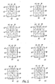
- the method of selection of the next boundary pixel is easily envisaged by thinking in terms of an order of search and selection of the first boundary pixel found, it is preferred in an adaptive boundary tracing system to use a fixed order of search of the surrounding pixels and assign each position a priority dependent on the direction from which the present boundary pixel was approached. The adjacent boundary pixel having the highest priority is then selected. This process being called the search algorithm.
- each figure shows a central boundary pixel 36 and eight adjacent pixels 37 to 44.
- Each central pixel 36 contains an arrow 45.
- the arrow 45 refers to the direction of the entrance path in each case, and the numbers in the adjacent pixels 37 to 44 give the priority order in which the adjacent pixels 37 to 44 will be selected if they are boundary pixels, the lowest numbers having the highest priority.
- a first boundary pixel 18 is found in an image.
- the initial entrance direction is left to right (normal sequential scanning sequence), so the priority sequence shown in Figure 5A is used so the two adjacent boundary pixels 19 and 33 are assigned priorities of 7 and 3 respectively and as a result the boundary pixel 33 is selected as the next boundary pixel in sequence.
- Boundary pixel 18 is deleted and the process is repeated for pixels 33, 32 and 31, in each of these cases only one adjacent boundary pixel is present, so it is selected.
- boundary pixel 30 the entrance direction is diagonally to the right and down so the priority sequence shown in Figure 5H is used, so the two adjacent boundary pixels 29 and 34 are given priorities of 3 and 5 respectively, so pixel 29 is selected as the next boundary pixel.
- boundary pixel 29 the entrance direction is downwards to the priority sequence shown in Figure 5G is used and the adjacent boundary pixels 27, 28 and 34 are given priorities of 3, 2 and 5 respectively so pixel 28 is selected as the next boundary pixel.
- boundary pixel 28 the entrance direction is downwards so the priority sequence shown in Figure 5G is again used and the adjacent boundary pixels 27 and 34 are assigned priorities of 5 and 7 respectively so pixel 27 is selected as the next boundary pixel.
- boundary pixel 26 the entrance direction is again right to left so the priority sequence of figure 5E is used and the adjacent boundary pixels 25, 34 and 35 are assigned priorities of 2, 7 and 5 respectively so pixel 25 is selected.
- boundary pixel 25 the entrance direction is again right to left so the priority sequence of Figure 5E is used and the adjacent boundary pixels 24 and 35 are assigned priorities of 2 and 7 respectively so the pixel 24 is selected.
- boundary tracer will always take the outermost pixels when tracing, and it can be seen that successful tracing takes place.
- the adapative boundary tracer has classified all the binary pixels so that those points which belong to the same object are grouped together for subsequent analysis.
- a 3 bit code, chain code, is used to define the direction of trace.
- a chain of codes is all that needs to be passed over to the Boundary Data Analyser for subsequent analysis and object classification, Process 4.
- the start and end of tracing sequences must always be marked in some way.
- the adaptive tracing requires a whole boundary to be processed before another can be started. This implies a non-sequential nature of accessing binary data from the store. Thus it is necessary for the boundary tracer to work on a whole frame of data. For this reason data from a video scanning system passing along a line 46 is stored in a first binary image store 47.
- the binary image store 47 stores an entire frame of the image and then switches it to a second binary image store 48. This switch will occur then the processing of a whole video image in the first store 47 and the capturing of a new video image in the second store 48 are both complete.
- the data entering along line 46 has already been operated on by the previously described processes 1 and 2 such that a boundary pixel is represented by a binary "1" value and a non-boundary pixel by a binary "0" value.
- the binary image store 48 is accessed by a pixel address generator 49.
- the pixel address generator is cleared just before the switching of a frame of data from the first binary image store 47 to the second binary image store 48.
- the pixel address generator 49 will provide a normal sequential addressing sequence through the frame stored in the second binary image store 48.
- the pixel address generator 49 will address the binary image store 48. When a first binary one pixel is addressed the pixel address generator value is preserved in a start address latch 50. Once preserved then a window sequence generator 51 will go through a ten clock cycle sequence. The output codes from the window sequence generator 51 will be decoded by a sequence controller 52. The sequence controller 52 uses these codes to produce signals which are supplied to the pixel address generator 49 to steer it through a desired window sequence. The first eight clock cycles will cause the pixel address generator 49 to provide the addresses of the neighbouring pixels to the first binary one pixel to the binary image store in a sequence shown in Figure 8. Each of the surrounding pixel values is clocked into a serial in parallel out (SIPO) register 53. The 9th clock cycle of the window sequence generator sequence causes the pixel address generator 49 to return to the first binary one pixel address. The 10th clock cycle initiates one of two events depending on whether or not one of the neighbouring pixels is a binary one pixel.
- SIPO serial in parallel out
- the values of the eight neighbouring pixels are supplied by the SIPO register 53 to a chain code look up table 54.
- the chain code look up table 54 contains the eight search priority sequences shown in Figures 5A to 5H, for the first boundary pixel found the priority sequence 1 shown in Figure 5A is used.
- the chain code look up table 54 compares the values of the eight neighbouring pixels with the priority sequence and selects the neighbouring binary one pixel having the highest priority and generates a chain code defining the direction of trace to this pixel which is supplied to the sequence controller 52, a latch 55 and a flag generator 56.
- the chain code from the chain code look-up table will have an active qualifying bit.
- the sequence contoller 52 integrates this bit and causes the pixel address generator 49 to move onto the new adjoining pixel address as defined by the chain code. Also, the chain code, which defines the direction of tracing is stored in the latch 55.
- the priority sequence used is selected by the chain code look up table 54 depending on the previous chain code which is supplied to the chain code look up table 54 by latch 55. Thus the priority sequence used is dependent on the direction of trace.
- sequence controller 52 Prior to movement to the new adjoining pixel the sequence controller 52 changes the value of the present boundary pixel in the second binary image store 48 from a one to a zero, and supplies the address of the present boundary pixel to an analyser interface unit 57.
- the chain code qualifying bit will be inactive.
- the sequence contoller 52 on intergrating this bit will load the preserved pixel start address from the pixel start address latch 50 into the pixel address generator 49 to resume the normal sequential image scanning until the next boundary pixel cluster is detected, and will change the value of the present boundary pixel in the second binary image store 48 from a one to a zero.
- the chain code look up table is divided into eight pages.
- the page selected is dependent on the latched chain code from the previous trace and thus on the direction of tracing, or for the first boundary pixel in a chain the page used is pre-set.
- the page selected is then addressed by the surround pixel values stored in the SIPO. So the selected page will have a search algorithm, for use on the data from the SIPO 53 as defined by the priority orders in Figure 5.
- the resulting chain code and qualifer provides sequencing information to the sequence controller 52.
- the boundary pixel address is sent to the Analyser Interface Unit 57, in this case a first in first out, FIFO.
- the Flag Generator 56 In response to control signals from the sequence controller 52. These flags indicate the start and end of a boundary trace and end of each frame of processing.
- the analyser interface unit 57 sends its data along line 58 to a boundary analyser (not shown) where process 4 is carried out.
- the chain code only could be passed to the Analyser Interface Unit 57.
- the start address of a boundary trace will be required by the boundary analyser and all subsequent boundary pixels will be defined by the chain code.
- the end of a boundary will be marked by an end of boundary flag.
Landscapes
- Engineering & Computer Science (AREA)
- Physics & Mathematics (AREA)
- General Physics & Mathematics (AREA)
- Multimedia (AREA)
- Theoretical Computer Science (AREA)
- Computer Vision & Pattern Recognition (AREA)
- Image Analysis (AREA)
Applications Claiming Priority (2)
| Application Number | Priority Date | Filing Date | Title |
|---|---|---|---|
| GB8808621 | 1988-04-12 | ||
| GB8808621A GB2217496B (en) | 1988-04-12 | 1988-04-12 | Improvements to boundary tracing |
Publications (2)
| Publication Number | Publication Date |
|---|---|
| EP0341819A2 true EP0341819A2 (de) | 1989-11-15 |
| EP0341819A3 EP0341819A3 (de) | 1991-11-27 |
Family
ID=10635056
Family Applications (1)
| Application Number | Title | Priority Date | Filing Date |
|---|---|---|---|
| EP19890303358 Ceased EP0341819A3 (de) | 1988-04-12 | 1989-04-05 | System und Verfahren zum Grenzentrassieren |
Country Status (2)
| Country | Link |
|---|---|
| EP (1) | EP0341819A3 (de) |
| GB (1) | GB2217496B (de) |
Cited By (2)
| Publication number | Priority date | Publication date | Assignee | Title |
|---|---|---|---|---|
| EP1600909A2 (de) | 2004-05-28 | 2005-11-30 | Toyota Jidosha Kabushiki Kaisha | Fahrspurdetektor |
| CN115601697A (zh) * | 2022-09-30 | 2023-01-13 | 山东省科学院自动化研究所(Cn) | 一种面向太赫兹安检图像的前处理方法 |
Families Citing this family (1)
| Publication number | Priority date | Publication date | Assignee | Title |
|---|---|---|---|---|
| JP3415270B2 (ja) * | 1994-06-03 | 2003-06-09 | ソニー株式会社 | 画像信号符号化方法及び復号方法 |
Family Cites Families (4)
| Publication number | Priority date | Publication date | Assignee | Title |
|---|---|---|---|---|
| GB1106972A (en) * | 1964-01-30 | 1968-03-20 | Mullard Ltd | Improvements in or relating to character recognition systems |
| DE3176044D1 (en) * | 1980-05-27 | 1987-04-30 | Texas Instruments Inc | Didactic device such as doll having simulated sight and voice |
| JPS5851388A (ja) * | 1981-09-22 | 1983-03-26 | Ricoh Co Ltd | 方向コ−ド割付け方法 |
| US4628532A (en) * | 1983-07-14 | 1986-12-09 | Scan Optics, Inc. | Alphanumeric handprint recognition |
-
1988
- 1988-04-12 GB GB8808621A patent/GB2217496B/en not_active Expired - Lifetime
-
1989
- 1989-04-05 EP EP19890303358 patent/EP0341819A3/de not_active Ceased
Cited By (4)
| Publication number | Priority date | Publication date | Assignee | Title |
|---|---|---|---|---|
| EP1600909A2 (de) | 2004-05-28 | 2005-11-30 | Toyota Jidosha Kabushiki Kaisha | Fahrspurdetektor |
| EP1600909A3 (de) * | 2004-05-28 | 2007-04-04 | Toyota Jidosha Kabushiki Kaisha | Fahrspurdetektor |
| US7307545B2 (en) | 2004-05-28 | 2007-12-11 | Toyota Jidosha Kabushiki Kaisha | Vehicle lane detector |
| CN115601697A (zh) * | 2022-09-30 | 2023-01-13 | 山东省科学院自动化研究所(Cn) | 一种面向太赫兹安检图像的前处理方法 |
Also Published As
| Publication number | Publication date |
|---|---|
| EP0341819A3 (de) | 1991-11-27 |
| GB8808621D0 (en) | 1988-08-24 |
| GB2217496B (en) | 1991-10-16 |
| GB2217496A (en) | 1989-10-25 |
Similar Documents
| Publication | Publication Date | Title |
|---|---|---|
| US5889885A (en) | Method and apparatus for separating foreground from background in images containing text | |
| US4757551A (en) | Character recognition method and system capable of recognizing slant characters | |
| US5796868A (en) | Object edge point filtering system for machine vision | |
| US4764971A (en) | Image processing method including image segmentation | |
| US4791676A (en) | Method and means for efficiently handling boundary conditions in connected component labeling | |
| US4162482A (en) | Pre-processing and feature extraction system for character recognition | |
| US5048107A (en) | Table region identification method | |
| US4665441A (en) | Method and system for line-thinning in electronic image processing | |
| JPH0315793B2 (de) | ||
| EP0173098A2 (de) | Verfahren und Gerät zum Folgen einer Musterkontur | |
| Kunt | Edge detection: A tuttorial review | |
| EP0156344B1 (de) | Anlage zum Verarbeiten und Segmentieren von Bildern | |
| JP2670273B2 (ja) | 画像処理装置 | |
| Kise et al. | Page segmentation based on thinning of background | |
| EP0627844B1 (de) | Bildprozessor | |
| EP0341819A2 (de) | System und Verfahren zum Grenzentrassieren | |
| US5034992A (en) | Image processing method | |
| US4138662A (en) | Character reader | |
| US4246570A (en) | Optical wand for mechanical character recognition | |
| CN111914846A (zh) | 版面数据合成方法、设备及存储介质 | |
| EP0216158A2 (de) | Vorrichtung zur Analyse des Zusammenhanges von Pixeln in einem rasterabgetasteten Teilbild | |
| JP3164835B2 (ja) | 人物画像認識における前処理方法および後処理方法 | |
| JPS623475B2 (de) | ||
| WO1990001750A1 (en) | Intelligent scan image processor | |
| Cordella et al. | Contour filling for region extraction |
Legal Events
| Date | Code | Title | Description |
|---|---|---|---|
| PUAI | Public reference made under article 153(3) epc to a published international application that has entered the european phase |
Free format text: ORIGINAL CODE: 0009012 |
|
| 17P | Request for examination filed |
Effective date: 19890502 |
|
| AK | Designated contracting states |
Kind code of ref document: A2 Designated state(s): DE FR IT NL SE |
|
| D17P | Request for examination filed (deleted) | ||
| PUAL | Search report despatched |
Free format text: ORIGINAL CODE: 0009013 |
|
| AK | Designated contracting states |
Kind code of ref document: A3 Designated state(s): DE FR IT NL SE |
|
| R17P | Request for examination filed (corrected) |
Effective date: 19920310 |
|
| RAP1 | Party data changed (applicant data changed or rights of an application transferred) |
Owner name: GEC-MARCONI LIMITED (NO. 53403 - FORMERLY THE MARC |
|
| 17Q | First examination report despatched |
Effective date: 19940620 |
|
| STAA | Information on the status of an ep patent application or granted ep patent |
Free format text: STATUS: THE APPLICATION HAS BEEN REFUSED |
|
| 18R | Application refused |
Effective date: 19951116 |