EP0341769A1 - Bildinterpolierungsgerät mit Bewegungsabschätzung und Kompensation und aus einem solchen Gerät bestehendes Konvertierungssystem für Fernsehstandards - Google Patents
Bildinterpolierungsgerät mit Bewegungsabschätzung und Kompensation und aus einem solchen Gerät bestehendes Konvertierungssystem für Fernsehstandards Download PDFInfo
- Publication number
- EP0341769A1 EP0341769A1 EP89201050A EP89201050A EP0341769A1 EP 0341769 A1 EP0341769 A1 EP 0341769A1 EP 89201050 A EP89201050 A EP 89201050A EP 89201050 A EP89201050 A EP 89201050A EP 0341769 A1 EP0341769 A1 EP 0341769A1
- Authority
- EP
- European Patent Office
- Prior art keywords
- image
- vector
- point
- block
- images
- Prior art date
- Legal status (The legal status is an assumption and is not a legal conclusion. Google has not performed a legal analysis and makes no representation as to the accuracy of the status listed.)
- Granted
Links
Images


Classifications
-
- H—ELECTRICITY
- H04—ELECTRIC COMMUNICATION TECHNIQUE
- H04N—PICTORIAL COMMUNICATION, e.g. TELEVISION
- H04N7/00—Television systems
- H04N7/01—Conversion of standards, e.g. involving analogue television standards or digital television standards processed at pixel level
- H04N7/0135—Conversion of standards, e.g. involving analogue television standards or digital television standards processed at pixel level involving interpolation processes
- H04N7/014—Conversion of standards, e.g. involving analogue television standards or digital television standards processed at pixel level involving interpolation processes involving the use of motion vectors
-
- G—PHYSICS
- G06—COMPUTING OR CALCULATING; COUNTING
- G06T—IMAGE DATA PROCESSING OR GENERATION, IN GENERAL
- G06T7/00—Image analysis
- G06T7/20—Analysis of motion
- G06T7/223—Analysis of motion using block-matching
-
- G—PHYSICS
- G06—COMPUTING OR CALCULATING; COUNTING
- G06T—IMAGE DATA PROCESSING OR GENERATION, IN GENERAL
- G06T2207/00—Indexing scheme for image analysis or image enhancement
- G06T2207/10—Image acquisition modality
- G06T2207/10016—Video; Image sequence
Definitions
- the present invention relates to a device for interpolating images by motion estimation and compensation, device constituted from a motion estimation member in blocks to form motion vectors assigned to blocks of image points and an interpolation member for forming an image as a function of said motion vectors.
- the present invention therefore provides a device of the kind mentioned above which gives a motion vector for any point or a few points while remaining insensitive to noise.
- such a device is remarkable in that it comprises an allocation member for assigning, among candidate motion vectors developed by the estimation member, a motion vector for at least one image point called the current point.
- the present invention also relates to a standard converter system formed from such a device.
- An example of conversion is that which consists in transforming images appearing at the rate of 50 Hz into images of frame rate 60 Hz (or more exactly 59.94 Hz). Therefore, it is impossible to match the images; the images to be formed at the rate of 59.94 Hz are obtained by interpolation from the images at 50 Hz.
- the following articles describe systems of this kind: "Môvement-Compensated Frame-Frequency Conversion of Television Signal” HIROHISA YAMAGUCHI et al . IEEE Transactions on Communications, vol.COM-35,? 10. Oct. 1987. "HDTV-PAL Standards Converter” YUTALEA TANAKA et al. NHK Laboratories Note, Jan. 1986, N series 326.
- a device of the above kind includes a motion vector coherence test member to provide a validation signal for each motion vector assigned to a point, for example. comparison with corresponding points located in images of said succession, brings the advantage of avoiding certain ambiguities on the determination of the motion vector. These ambiguities arise in particular for objects of reduced size moving in a continuous background. Certain portions of the object will be assigned a good motion vector but others may be assigned the motion vector corresponding to the background. The interpolated image will show discontinuities in the reproduction of this object and these discontinuities will appear in different places of the image during a succession of these. The object will finally appear in a degraded manner. Thanks to this characteristic of the invention, this degradation and these discontinuities are largely avoided by comparing the motion vectors both in a spatial domain surrounding the point of the image and in domains surrounding the corresponding points in different images.
- FIG. 1 there is shown with reference 1 the device of the invention.
- This device comprises, first of all, a first port 2 for receiving image information and a second port 3 for providing the interpolated image.
- This interpolated image depends on a parameter ⁇ applied to a fourth access 4.
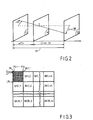
- This parameter a is defined as follows. For this, reference is made to FIG. 2.
- E1 and E2 be two successive images appearing in times distant by a duration TR.
- the device of the invention proposes to provide, by interpolation, a missing image M located in time at ⁇ .TR of E1 and at (1-a) .TR of E2 with a between 0 and 1.
- the device of the invention comprises, first of all a member for estimating movement by blocks 10.
- This member will provide for a block of, for example 16 ⁇ 16 image points, a vector D .
- Figure 3 we have shown the decomposition of an image into blocks. Each image is made up of 1540 blocks. These blocks are organized into 35 lines of 44 blocks. So blocks BK1,1; BK1,2; ... BK1,44 belong to the first line, blocks BK2,1; BK2,2; ... BK2,44 on the second line, and so on until blocks BK35,1; BK35,2; ... BK35,44 which belong to the thirty fifth line.
- Each block is made up of 16 lines L1, L2, L3, ... L16 each of which contains 16 points P1, P2, ... P16: this is only detailed for block BK1,1.
- the member 10 will provide for each block BKm, n of the image M, a motion vector D m, n.
- the member 10 is provided with a plurality of elementary members 11 ', 11 ", ... 11 (11) . These members provide a motion vector D i + 1 , D" i + 1 , .. . for a given block, defined by the content of a block counter 15.
- This counter 15 associated with a decoding circuit 17 will address a memory circuit 20 containing all the luminance information of the images E1 and E2 from which we are going to develop the image M.
- This circuit 17 will only supply in the direction of the elementary organs 11 ', 11'', ... 11 (n) the information necessary to establish the values of the motion vector D' i + 1 , D " i + 1 , ...
- a circuit 21 determines the best according to a certain criterion defined by quality information Q ', Q ", ... Q (n) produced by each elementary member 11', 11 '', ... 11 (n). This circuit 21 controls, as a function of this, the position of a multiplexer 22 so that the vector selected Dm, n is recorded in a second memory circuit 30 in a place assigned to the block BKm, n.
- the elementary organs operate according to the C.CAFFORIO and ROCCA algorithm described in the aforementioned article Any other algorithm providing motion vectors is also suitable and naturally falls within the scope of the invention.
- a correction value ⁇ is added to an earlier value according to an iterative process so that one can write: This can be done multiple times.
- the initial values can be taken by considering the motion vector of neighboring blocks already calculated.
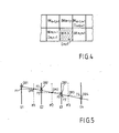
- n we will take as initial values D m-1, n + 1 and D m, n-1 (see FIG. 4) which are the motion vectors assigned to the blocks BKm-1 , n + 1 and BKm, n-1 treated previously therefore and the vectors have already been calculated.
- the zero motion vector can also be considered.
- the quantity Q (i) analyzed by circuit 21 relative to a vector is given by:
- the vector retained will be the one for which the quantity Q (i) will be minimum.
- These vectors are taken from the memory circuit 30 and stored for calculation in a register 52.
- the memory circuit 30 is addressed by a transcoding circuit 57 controlled by a picture point counter 55, this circuit 57 determining in particular for the current point the candidate movement vectors to be processed by the allocation unit 50.
- a decision circuit 62 receiving the results of the different elementary allocation bodies determines the vector DP taken from these candidates.
- This vector is selected by means of a switch 65 controlled by the circuit 62.
- the CT (z, Dc) function associated with the current point and with each candidate motion vector is examined at the level of the circuit 62.
- This CT (z, Dc) function is such that: B is a domain of reduced size compared to A.
- B is constituted by 8 points surrounding the current point.
- the device of the invention also includes a motion vector consistency test member 80.
- a motion vector consistency test member 80 To understand the advantage of such a member, reference is made to FIG. 5.
- E1 is shown. , E2, E3, E4 a horizontal section of a sequence of images.
- OB represents an object which moves according to this section.
- the image E1 the object occupies the place OB1
- the image e2 the object occupies the place OB2
- the image E3 occupies the place OB3
- the object occupies the place OB3
- the image E4 the object occupies the place OB4.
- this object OB moves in a uniform bottom and on the other hand that the values of displacements of the object and the bottom are known.
- the locations OB1 and OB2 give a good correlation but F1 and F2, which correspond to the background, also give a good correlation so that in OM1 there will be randomly either an interpolation between OB1 and OB2, or an interpolation between F1 and F2. This indeterminacy will occur for OM2, for OM3 so that the object or parts of itself appear for certain missing images and do not appear for others.
- the similarity circuit 95 cooperating with the circuit 86 determines, in a first step, whether the vector D D is similar to the other vectors provided by circuit 86.
- the circuit provides, in a second step, the similarity signal if a certain number of vectors of the DDN domain are similar.
- circuits 82 and 84 also provide similarity signals relating to the DDF and DDP domains and with respect to this same DD vector.
- a final coherence member 98 provides at its output, for each current point a coherence signal giving the result of the coherence considered both on the present image and on the anterior and posterior images.
- a coherence signal giving the result of the coherence considered both on the present image and on the anterior and posterior images.
- there is coherence if, at least one signal of similarity is provided by one of the circuits 82, 84 and 95.
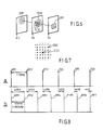
- a decision filtering unit 100 analyzes in a DSS domain surrounding the point (cf. FIG. 7) the coherence decisions made by the final coherence body 98 to provide a validity signal indicating that the vector DD assigned to the point Z is valid given the consistency of the vectors assigned to points in this DSS domain.
- This DSS domain is for example extended to 17.AX by 17.AY.
- This filtering can correspond in the simplest case to a majority decision of coherence in the DSS domain, therefore greater than 144.
- an interpolation calculation unit 120 performs for any point Z of the images to be interpolated, the calculation indicated by formula (1) above if the validity signal is positive or the calculation given by the following formula relating to a vector movement if the validity signal is negative:
- the memory circuit 20 is described.
- a circuit 230 by counting the different images, provides an interpolation mark from which ⁇ can be determined. This value a is used in the various treatments.
- the interpolation mark is assigned to each incoming image.
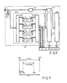
- the arrangement 200 is formed by four memories MY1, MY2, MY3 and MY4, the capacity of which is sufficient to record an entire image of points. These four memories are assigned a circuit write 250 and a read circuit 260. Figure 10 shows how this arrangement works. Each incoming image is recorded in turn in one of the memories MY1 to MY4. Thus at the instant tw1 the image EE1 is stored in the memory MY1, at the instant tw2 the image EE2 is stored in the memory MY2 and so on for the instants tw3 and tw4 where the images EE3 and EE4 are stored in memories MY3 and MY4.
- a new cycle begins for the images EE5, EE6, EE7, EE8 which are recorded in the memories MY1 to MY4.
- the different instants tw1, tw2, ... tw5 are separated by a duration equal to 1/50 Hz.
- the reading circuit 260 will make information concerning two successive images available to the different organs.
- the memories MY1 and MY2 containing the information of the images EE1 and EE2 are made available; then at time tr2 these are the memories MY2 and MY3 concerning the images EE2 and EE3 and this so on until time tr6 where an interpolation mark is detected indicating that from two identical images two interpolations are performed.
- FIG. 10 there are two interpolations to be carried out on the images EE6 and EE7 contained in the memories MY2 and MY3.
- FIG. 12 the structure of the elementary members 11 ... 11 (n) has been shown in detail.
- These members include two working memories 301 and 302 each provided to contain the information of two consecutive different images. These memories are loaded from the decoding circuit 17 as has been said.
- This vector dd is equal to ad for the member 311 and to (1-a) d for the member 312.
- the value a is determined from the interpolation mark coming from the memory circuit 20.
- a calculation circuit 350 determines the values ⁇ and Q (see formulas (3), (4) and (10) from prior operations carried out by circuits 351 to 357.
- a final adder 370 performs the operation which gives D i + 1 .
- the circuit 351 performs the calculation of DFD.
- the circuits 352 and 353 respectively perform the horizontal and vertical gradient calculations of the image contained in the memory 301.
- the circuits 354 and 355 respectively perform the horizontal and vertical gradient calculations of the image contained in the memory 302.
- Circuit 356 calculates the horizontal gradient in the image to be interpolated by applying formula (6) and circuit 357 the vertical gradient by applying formula (7).
- These organs include two working memories 401 and 402 each provided to contain information relating to two different consecutive images. These memories are connected to the memory circuit 20 using the decoding circuit 57.
- This elementary member 60-c also includes, attached to each of the memories 401 and 402, two linear interpolation members 411 and 412, for perform interpolations on the fractional part of the candidate vector Dc.
- the memories 401 and 402 are addressed from the counter 55.
- an addressing circuit 422 will address the image points concerned by the calculation which will be carried out by a member 450.
- the value a is developed as a function of the interpolation mark coming from of circuit 20.
- Unit 450 performs the calculation given by formula (11).
- FIG. 15 shows in more detail the structure of the processing members 82 and 84 forming part of the coherence member 80. It is formed of a distribution circuit 600 which provides for each displacement vector the other eight corresponding to the DDP and DDF already defined. These nine vectors are stored in a memory circuit 605. A vector Dch whose consistency we want to ensure is applied to an addressing circuit 608 used for reading the memory 605. At the output of the memory 605, the nine vectors of the DDP or DDF domain are obtained to be compared with the vector Dch. It is the comparison circuit 610 which performs this operation. This circuit provides the result of each comparison with Dch. A circuit similar to circuit 95 provides the similarity signal by counting similar vectors by means of a circuit 620 and comparing them to a threshold value by means of comparator 622.
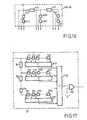
- FIG. 16 shows in detail the distribution circuit 600 similar to the distribution circuit 86.
- These circuits are formed from line delay elements 610 and 611 connected in cascade and providing a delay equal to the duration of a line.
- element 610 which constitutes the input of these circuits, two delay elements points 620 and 621 have been placed, each causing a delay equal to the duration which separates two image points.
- two point delay elements 630 and 631 are arranged at the output of element 610 and at the output of element 611 two point delay elements 640 and 641.
- the output signals of these circuits 600, 86 are considered at the entry of element 610 and at the exits of elements 620, 621, 610, 630, 631, 611, 640 and 641. It is found that these exits indeed provide the required indications concerning the domains DDF, DDN and DDP.
- the decision filtering member 100 is detailed, which here simply makes a majority decision. It is made up of a cascade of line delay elements 701 to 715, the number of which depends on the vertical magnitude of the DSS domain (17. ⁇ X ⁇ 17. ⁇ Y). At the input of element 701 and at the outputs of elements 701, 702, ... and 716 are connected different cascades of delay elements point 711, 712, ... 726 for the first 731, 732, .. 736 for the second and so on until the last with the elements 991, 992, ... 1026. Different adders 1111 to 1127 add the results of these cascades.
Landscapes
- Engineering & Computer Science (AREA)
- Multimedia (AREA)
- Signal Processing (AREA)
- Computer Vision & Pattern Recognition (AREA)
- Physics & Mathematics (AREA)
- General Physics & Mathematics (AREA)
- Theoretical Computer Science (AREA)
- Television Systems (AREA)
- Image Analysis (AREA)
- Processing Or Creating Images (AREA)
Applications Claiming Priority (2)
| Application Number | Priority Date | Filing Date | Title |
|---|---|---|---|
| FR8805775A FR2630842B1 (fr) | 1988-04-29 | 1988-04-29 | Dispositif pour interpoler des images par estimation et compensation de mouvement et systeme convertisseur de standards de television constitue a partir d'un tel dispositif |
| FR8805775 | 1988-04-29 |
Publications (2)
| Publication Number | Publication Date |
|---|---|
| EP0341769A1 true EP0341769A1 (de) | 1989-11-15 |
| EP0341769B1 EP0341769B1 (de) | 1994-07-13 |
Family
ID=9365842
Family Applications (1)
| Application Number | Title | Priority Date | Filing Date |
|---|---|---|---|
| EP89201050A Expired - Lifetime EP0341769B1 (de) | 1988-04-29 | 1989-04-24 | Bildinterpolierungsgerät mit Bewegungsabschätzung und Kompensation und aus einem solchen Gerät bestehendes Konvertierungssystem für Fernsehstandards |
Country Status (6)
| Country | Link |
|---|---|
| US (1) | US5060064A (de) |
| EP (1) | EP0341769B1 (de) |
| JP (1) | JPH02504216A (de) |
| DE (1) | DE68916698T2 (de) |
| FR (1) | FR2630842B1 (de) |
| WO (1) | WO1989010600A1 (de) |
Cited By (3)
| Publication number | Priority date | Publication date | Assignee | Title |
|---|---|---|---|---|
| EP0390660A1 (de) * | 1989-03-31 | 1990-10-03 | THOMSON multimedia | Verfahren und Einrichtung zur temporalen Interpolation von Bildern mit korrigierter Bewegungskompensation |
| DE4015390A1 (de) * | 1990-05-14 | 1991-11-21 | Nokia Unterhaltungselektronik | Verfahren zum berechnen des inhalts eines zwischenbildes zu jeweils zwei aufeinanderfolgenden monitorbildern |
| WO1994001970A1 (en) * | 1992-07-03 | 1994-01-20 | Snell & Wilcox | Motion compensated video processing |
Families Citing this family (19)
| Publication number | Priority date | Publication date | Assignee | Title |
|---|---|---|---|---|
| FR2651405B1 (fr) * | 1989-08-29 | 1992-05-22 | Philips Electronique Lab | Procede et dispositif de traitement d'images a estimation de mouvement amelioree. |
| DE69029999T2 (de) * | 1990-07-20 | 1997-08-14 | Philips Electronics Nv | Vorrichtung zur Verarbeitung von Bewegungsvektoren |
| DE69116036T2 (de) * | 1990-08-28 | 1996-08-01 | Philips Electronics Nv | Verfahren und Anordung zum Verringern der Bewegungsabschätzapparatur und der Anforderungen an die Datenübertragungskapazität in Video-Systemen |
| FR2678464A1 (fr) * | 1991-06-27 | 1992-12-31 | Thomson Csf | Procede de conversion du rythme temporel d'une sequence d'images animees. |
| CA2114028C (en) * | 1991-07-23 | 1998-04-28 | Mark Andrew Shackleton | Method and device for frame interpolation of a moving image |
| JP2873338B2 (ja) * | 1991-09-17 | 1999-03-24 | 富士通株式会社 | 動物体認識装置 |
| DE69334277D1 (de) * | 1992-11-05 | 2009-05-28 | Canon Kk | Vorrichtung und Verfahren zur Verarbeitung von Bewegtbildern |
| GB2301726B (en) * | 1992-11-10 | 1997-05-14 | Sony Uk Ltd | Motion compensated video signal processing |
| GB2283385B (en) * | 1993-10-26 | 1998-04-01 | Sony Uk Ltd | Motion compensated video signal processing |
| DE69510851T2 (de) * | 1994-03-30 | 1999-12-02 | Thomson Multimedia, Boulogne | Verfahren und Gerät zur Reduzierung von Umwandlungsartefakten |
| KR100287211B1 (ko) * | 1994-08-30 | 2001-04-16 | 윤종용 | 양방향 움직임 추정방법 및 장치 |
| US6341144B1 (en) | 1996-09-20 | 2002-01-22 | At&T Corp. | Video coder providing implicit coefficient prediction and scan adaptation for image coding and intra coding of video |
| US8625665B2 (en) * | 1996-09-20 | 2014-01-07 | At&T Intellectual Property Ii, L.P. | Video coder providing implicit coefficient prediction and scan adaptation for image coding and intra coding of video |
| US6340990B1 (en) * | 1998-03-31 | 2002-01-22 | Applied Intelligent Systems Inc. | System for deinterlacing television signals from camera video or film |
| US20030171665A1 (en) * | 2002-03-05 | 2003-09-11 | Jiang Hsieh | Image space correction for multi-slice helical reconstruction |
| US7519229B2 (en) * | 2004-03-30 | 2009-04-14 | Apple, Inc. | Video coding system providing separate coding chains for dynamically selected small-size or full-size playback |
| JP4453647B2 (ja) | 2005-10-28 | 2010-04-21 | セイコーエプソン株式会社 | 動画像表示装置および動画像表示方法 |
| US8582656B2 (en) * | 2007-04-13 | 2013-11-12 | Apple Inc. | Method and system for video encoding and decoding |
| US8619874B2 (en) * | 2007-04-13 | 2013-12-31 | Apple Inc. | Method and system for video encoding and decoding |
Citations (2)
| Publication number | Priority date | Publication date | Assignee | Title |
|---|---|---|---|---|
| GB2153625A (en) * | 1984-01-30 | 1985-08-21 | Kokusai Denshin Denwa Co Ltd | Movement estimation system for video signals |
| GB2172171A (en) * | 1985-03-04 | 1986-09-10 | Kokusai Denshin Denwa Co Ltd | Motion vector calculating system for detecting a moving object on a screen |
Family Cites Families (5)
| Publication number | Priority date | Publication date | Assignee | Title |
|---|---|---|---|---|
| US4442454A (en) * | 1982-11-15 | 1984-04-10 | Eastman Kodak Company | Image processing method using a block overlap transformation procedure |
| JPS6126382A (ja) * | 1984-07-17 | 1986-02-05 | Kokusai Denshin Denwa Co Ltd <Kdd> | 動き量を用いた動画像フレ−ムレ−ト変換方式 |
| JPS61113377A (ja) * | 1984-11-07 | 1986-05-31 | Sony Corp | テレビジヨン信号の動き検出装置 |
| DE3508094A1 (de) * | 1985-03-07 | 1986-09-11 | Fa. Carl Zeiss, 7920 Heidenheim | Kreuztisch fuer mikroskope |
| FR2624682B2 (fr) * | 1987-03-23 | 1990-03-30 | Thomson Csf | Procede et dispositif d'estimation de mouvement dans une sequence d'images animees |
-
1988
- 1988-04-29 FR FR8805775A patent/FR2630842B1/fr not_active Expired - Fee Related
-
1989
- 1989-04-24 EP EP89201050A patent/EP0341769B1/de not_active Expired - Lifetime
- 1989-04-24 DE DE68916698T patent/DE68916698T2/de not_active Expired - Fee Related
- 1989-04-26 JP JP1505703A patent/JPH02504216A/ja active Pending
- 1989-04-26 US US07/460,326 patent/US5060064A/en not_active Expired - Fee Related
- 1989-04-26 WO PCT/NL1989/000028 patent/WO1989010600A1/fr not_active Ceased
Patent Citations (2)
| Publication number | Priority date | Publication date | Assignee | Title |
|---|---|---|---|---|
| GB2153625A (en) * | 1984-01-30 | 1985-08-21 | Kokusai Denshin Denwa Co Ltd | Movement estimation system for video signals |
| GB2172171A (en) * | 1985-03-04 | 1986-09-10 | Kokusai Denshin Denwa Co Ltd | Motion vector calculating system for detecting a moving object on a screen |
Non-Patent Citations (1)
| Title |
|---|
| COMPUTER VISION, GRAPHICS, AND IMAGE PROCESSING, vol. 21, no. 2, février 1983, pages 262-279, Academic Press, Inc.; M. YACHIDA: "Determining velocity maps by spatio-temporal neighborhoods from image sequences" * |
Cited By (6)
| Publication number | Priority date | Publication date | Assignee | Title |
|---|---|---|---|---|
| EP0390660A1 (de) * | 1989-03-31 | 1990-10-03 | THOMSON multimedia | Verfahren und Einrichtung zur temporalen Interpolation von Bildern mit korrigierter Bewegungskompensation |
| DE4015390A1 (de) * | 1990-05-14 | 1991-11-21 | Nokia Unterhaltungselektronik | Verfahren zum berechnen des inhalts eines zwischenbildes zu jeweils zwei aufeinanderfolgenden monitorbildern |
| EP0456906A3 (en) * | 1990-05-14 | 1992-04-22 | Nokia Unterhaltungselektronik (Deutschland) Gmbh | Method for evaluating the contents of an intermediate picture for every two following monitor pictures |
| WO1994001970A1 (en) * | 1992-07-03 | 1994-01-20 | Snell & Wilcox | Motion compensated video processing |
| AU668196B2 (en) * | 1992-07-03 | 1996-04-26 | Snell & Wilcox Limited | Motion compensated video processing |
| US5784114A (en) * | 1992-07-03 | 1998-07-21 | Snell & Wilcox Ltd | Motion compensated video processing |
Also Published As
| Publication number | Publication date |
|---|---|
| DE68916698T2 (de) | 1995-03-16 |
| US5060064A (en) | 1991-10-22 |
| FR2630842B1 (fr) | 1994-04-08 |
| WO1989010600A1 (fr) | 1989-11-02 |
| DE68916698D1 (de) | 1994-08-18 |
| JPH02504216A (ja) | 1990-11-29 |
| EP0341769B1 (de) | 1994-07-13 |
| FR2630842A1 (fr) | 1989-11-03 |
Similar Documents
| Publication | Publication Date | Title |
|---|---|---|
| EP0341769B1 (de) | Bildinterpolierungsgerät mit Bewegungsabschätzung und Kompensation und aus einem solchen Gerät bestehendes Konvertierungssystem für Fernsehstandards | |
| FR2693290A1 (fr) | Dispositif de détection de vecteur mouvement pour la compensation des mouvements dans une image animée. | |
| FR2638874A1 (fr) | Procede d'estimation du mouvement d'au moins une cible dans une suite d'images, et dispositif pour la mise en oeuvre de ce procede | |
| FR2594281A1 (fr) | Appareil d'estimation du bruit dans des signaux ayant des intervalles redondants | |
| FR2674653A1 (fr) | Procede et dispositif de detection de bord pour un systeme de traitement d'image. | |
| FR2593698A1 (fr) | Appareil d'examen de milieux en mouvement par echographie ultrasonore | |
| FR2851676A1 (fr) | Procede d'obtention d'une image a resolution augmentee par l'utilisation d'une pluralite d'images a faible resolution | |
| EP1259939B1 (de) | Verfahren und vorrichtung zur automatischen wahrnehmung | |
| US20230125150A1 (en) | Augmentation of testing or training sets for machine learning models | |
| FR2563677A1 (fr) | Perfectionnements concernant les systemes de traitement de signaux video | |
| FR2493649A1 (fr) | Dispositif convertisseur de balayage | |
| FR2719384A1 (fr) | Procédé de trajectographie d'objets et dispositif de mise en Óoeuvre de ce procédé. | |
| EP0286192B1 (de) | Verfahren und Gerät zur Bewegungsabschätzung in einer Bildfolge | |
| EP0241983B1 (de) | Bildverarbeitungsvorrichtung zur Schätzung der Verschiebung in Bildern befindlicher Objekte | |
| Abu et al. | Robust image denoising for sonar imagery | |
| EP0021948B1 (de) | Anlage zum Folgen und wiederholten Schätzen des lokalen Zustands von Bildkonturen und Anwendung zum adaptiven Vorhersagen der Differenz-Codierung von Fernsehsignalen | |
| EP0351003A1 (de) | Vorrichtung zur Abgrenzung von in Gegensatz gebrachten Gegenständen in einem Bild | |
| EP0294282B1 (de) | Verfahren zur temporalen Interpolation von Bildern und Einrichtung zur Durchführung dieses Verfahrens | |
| EP0410826A1 (de) | Iteratives Bewegungsabschätzungsverfahren zwischen einem Referenzbild und einem aktuellen Bild, und Verfahren zu ihrer Herstellung | |
| EP0224957B1 (de) | Verfahren und Einrichtung zur Bewegungsabschätzung in einer Bildfolge | |
| WO1995004963A1 (fr) | Dispositif electronique de calcul d'une transformee de fourier et procede pour minimiser la taille des chemins de donnees internes d'un tel dispositif | |
| EP0123573A1 (de) | Verfahren zum adaptiven Kodieren und Dekodieren eines Fernsehbildes und Vorrichtung zur Durchführung dieses Verfahrens | |
| FR2742902A1 (fr) | Procede d'estimation de mouvement | |
| EP0495759A1 (de) | Verfahren und Gerät zur Ableitung einer Hinderniskarte aus dem Empfängersignal eines Impuls-Abtastradars, für Fahrzeuge | |
| Rathore et al. | An Efficient VLSI Design of Threshold Filter using Removal of Impulse Noise using Wallace Tree Encoder |
Legal Events
| Date | Code | Title | Description |
|---|---|---|---|
| PUAI | Public reference made under article 153(3) epc to a published international application that has entered the european phase |
Free format text: ORIGINAL CODE: 0009012 |
|
| AK | Designated contracting states |
Kind code of ref document: A1 Designated state(s): DE FR GB |
|
| RAP1 | Party data changed (applicant data changed or rights of an application transferred) |
Owner name: N.V. PHILIPS' GLOEILAMPENFABRIEKEN Owner name: LABORATOIRES D'ELECTRONIQUE PHILIPS |
|
| 17P | Request for examination filed |
Effective date: 19900509 |
|
| 17Q | First examination report despatched |
Effective date: 19930203 |
|
| GRAA | (expected) grant |
Free format text: ORIGINAL CODE: 0009210 |
|
| AK | Designated contracting states |
Kind code of ref document: B1 Designated state(s): DE FR GB |
|
| REF | Corresponds to: |
Ref document number: 68916698 Country of ref document: DE Date of ref document: 19940818 |
|
| GBT | Gb: translation of ep patent filed (gb section 77(6)(a)/1977) |
Effective date: 19941005 |
|
| PLBE | No opposition filed within time limit |
Free format text: ORIGINAL CODE: 0009261 |
|
| 26N | No opposition filed | ||
| PGFP | Annual fee paid to national office [announced via postgrant information from national office to epo] |
Ref country code: GB Payment date: 19970401 Year of fee payment: 9 |
|
| PGFP | Annual fee paid to national office [announced via postgrant information from national office to epo] |
Ref country code: FR Payment date: 19970422 Year of fee payment: 9 |
|
| PGFP | Annual fee paid to national office [announced via postgrant information from national office to epo] |
Ref country code: DE Payment date: 19970624 Year of fee payment: 9 |
|
| PG25 | Lapsed in a contracting state [announced via postgrant information from national office to epo] |
Ref country code: GB Free format text: LAPSE BECAUSE OF NON-PAYMENT OF DUE FEES Effective date: 19980424 |
|
| PG25 | Lapsed in a contracting state [announced via postgrant information from national office to epo] |
Ref country code: FR Free format text: THE PATENT HAS BEEN ANNULLED BY A DECISION OF A NATIONAL AUTHORITY Effective date: 19980430 |
|
| GBPC | Gb: european patent ceased through non-payment of renewal fee |
Effective date: 19980424 |
|
| PG25 | Lapsed in a contracting state [announced via postgrant information from national office to epo] |
Ref country code: DE Free format text: LAPSE BECAUSE OF NON-PAYMENT OF DUE FEES Effective date: 19990202 |
|
| REG | Reference to a national code |
Ref country code: FR Ref legal event code: ST |