EP0341663B1 - Frost free heat exchanger - Google Patents
Frost free heat exchanger Download PDFInfo
- Publication number
- EP0341663B1 EP0341663B1 EP89108326A EP89108326A EP0341663B1 EP 0341663 B1 EP0341663 B1 EP 0341663B1 EP 89108326 A EP89108326 A EP 89108326A EP 89108326 A EP89108326 A EP 89108326A EP 0341663 B1 EP0341663 B1 EP 0341663B1
- Authority
- EP
- European Patent Office
- Prior art keywords
- fluid
- core
- front face
- array
- heat exchanger
- Prior art date
- Legal status (The legal status is an assumption and is not a legal conclusion. Google has not performed a legal analysis and makes no representation as to the accuracy of the status listed.)
- Expired - Lifetime
Links
- 239000012530 fluid Substances 0.000 claims description 66
- LYCAIKOWRPUZTN-UHFFFAOYSA-N Ethylene glycol Chemical compound OCCO LYCAIKOWRPUZTN-UHFFFAOYSA-N 0.000 description 3
- 238000001816 cooling Methods 0.000 description 1
- 230000007613 environmental effect Effects 0.000 description 1
- 239000000463 material Substances 0.000 description 1
- 238000002844 melting Methods 0.000 description 1
- 230000008018 melting Effects 0.000 description 1
- 239000002244 precipitate Substances 0.000 description 1
- 230000003014 reinforcing effect Effects 0.000 description 1
Images

Classifications
-
- F—MECHANICAL ENGINEERING; LIGHTING; HEATING; WEAPONS; BLASTING
- F28—HEAT EXCHANGE IN GENERAL
- F28F—DETAILS OF HEAT-EXCHANGE AND HEAT-TRANSFER APPARATUS, OF GENERAL APPLICATION
- F28F9/00—Casings; Header boxes; Auxiliary supports for elements; Auxiliary members within casings
- F28F9/02—Header boxes; End plates
- F28F9/026—Header boxes; End plates with static flow control means, e.g. with means for uniformly distributing heat exchange media into conduits
- F28F9/0278—Header boxes; End plates with static flow control means, e.g. with means for uniformly distributing heat exchange media into conduits in the form of stacked distribution plates or perforated plates arranged over end plates
-
- F—MECHANICAL ENGINEERING; LIGHTING; HEATING; WEAPONS; BLASTING
- F28—HEAT EXCHANGE IN GENERAL
- F28D—HEAT-EXCHANGE APPARATUS, NOT PROVIDED FOR IN ANOTHER SUBCLASS, IN WHICH THE HEAT-EXCHANGE MEDIA DO NOT COME INTO DIRECT CONTACT
- F28D9/00—Heat-exchange apparatus having stationary plate-like or laminated conduit assemblies for both heat-exchange media, the media being in contact with different sides of a conduit wall
- F28D9/0062—Heat-exchange apparatus having stationary plate-like or laminated conduit assemblies for both heat-exchange media, the media being in contact with different sides of a conduit wall the conduits for one heat-exchange medium being formed by spaced plates with inserted elements
- F28D9/0068—Heat-exchange apparatus having stationary plate-like or laminated conduit assemblies for both heat-exchange media, the media being in contact with different sides of a conduit wall the conduits for one heat-exchange medium being formed by spaced plates with inserted elements with means for changing flow direction of one heat exchange medium, e.g. using deflecting zones
-
- F—MECHANICAL ENGINEERING; LIGHTING; HEATING; WEAPONS; BLASTING
- F28—HEAT EXCHANGE IN GENERAL
- F28F—DETAILS OF HEAT-EXCHANGE AND HEAT-TRANSFER APPARATUS, OF GENERAL APPLICATION
- F28F19/00—Preventing the formation of deposits or corrosion, e.g. by using filters or scrapers
- F28F19/006—Preventing deposits of ice
-
- F—MECHANICAL ENGINEERING; LIGHTING; HEATING; WEAPONS; BLASTING
- F28—HEAT EXCHANGE IN GENERAL
- F28F—DETAILS OF HEAT-EXCHANGE AND HEAT-TRANSFER APPARATUS, OF GENERAL APPLICATION
- F28F9/00—Casings; Header boxes; Auxiliary supports for elements; Auxiliary members within casings
- F28F9/02—Header boxes; End plates
Definitions
- This invention relates to a plate fin heat exchanger capable of operation in extremely cold environments comprising the features as indicated in the pre-characterizing part of claim 1.
- Plate fin heat exchangers generally consist of a core formed of a plurality of stacked layers. Each layer has a plurality of continuously corrugated or finned elements which are arranged to form a plurality of channels. The channels in one layer may lie in transverse of parallel relation to the channels formed in adjacent layers. A parting sheet separates the adjacent layers, fluids having differing amounts of heat energy flow through the channels of adjacent layers so that heat energy may be transferred from fluid to fluid.
- Closure bars which isolate the fluids, are generally mounted on the sides of each layer parallel to the channels therein. Top and bottom sheets and reinforcing bars may be required to structurally support the core.
- US-A-32 62496 discloses a plate fin heat exchanger of the type defined in the pre-characterizing part of claim 1. Specific problems are encountered, if heat exchangers of this type are used in extremely cold environments.
- An air cycle ECS generally includes a compressor for pressurizing air input thereto, and a turbine for driving the compressor and for expanding and cooling the air.
- Some turbines are capable of delivering air at temperatures as low as 74°C below zero. At such cold temperatures, moisture within the air is precipitated out in the form of snow or ice. The snow and ice may clog and shut down any downstream components, such as heat exchangers. If a heat exchanger becomes clogged, heat transfer among the fluids flowing therethrough may be severely reduced.
- the air from the turbine may not warm to useable levels for other downstream components.
- the fluid, which warms the air from the turbine in the exchanger may not be cooled enough for effective downstream use.
- Prior art plate fin heat exchangers have difficulty in such extremely cold environments because of clogging due to ice and snow and cold spots in the heat exchanger core.
- the heat transfer rate between the air passing through the heat exchanger and a fluid being cooled is minimized while avoiding a snow/ice blockage of the heat exchanger.
- Snow and ice are prevented building up on a front face or within a heat exchanger.
- fins of the cold layers arranged upon the front face of the exchanger are recessed so that snow or ice impinges upon such fins between adjacent warm layers so that the temperature of closure bars arranged upon the front face is maximized.
- the baffle limits the flow of the cold fluid through a central area of the core, to distribute a flow of cold fluid across the front face of the core.
- Fig. 1 is perspective, partially exploded view of the heat exchanger of the invention.
- Fig. 2 is an expanded, sectional view of a front face of the heat exchanger taken along the line 2-2 of Fig. 1.
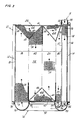
- Fig. 3 is a side view of the heat exchanger taken along the line 3-3 of Fig. 1.
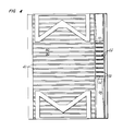
- Fig. 4 is a top view of the heat exchanger of Fig. 1.
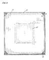
- Fig. 5 is a view of the back face of the heat exchanger of Fig. 1.
- a best mode embodiment of the plate fin heat exchanger 10 of the invention is shown.
- Such a heat exchanger would be typically used for exchanging heat energy between a relatively cold first fluid, such as air passing from the turbine of an air cycle machine (ACM, not shown), and a relatively warm second fluid.
- ACM air cycle machine
- such a heat exchanger may be used for any purpose for which heat exchangers are used, and particularly where extremely cold environments may be encountered.
- the heat exchanger 10 of the present invention has several portions including; a core 12 having a front face 14 and a back face 16, an inlet 18, a baffle 20 (see fig. 5), and an outlet 22.
- a relatively cold first fluid is directed to the front face 14 of the core 12.
- the first fluid flows through the core and exits through the back face 16 of the core.
- the inlet 18 directs a relatively warm second fluid to the core and the outlet 22 directs the second fluid from the core.
- the core 12 has twenty-five cold layers 24 through which the relatively cold first fluid flows, interspersed among twenty-six warm layers 26 through which the relatively warm second fluid flows.
- Each cold layer has a plurality of ruffled fins 28 arranged parallel to the flow of the cold air through the core, a top closure bar 30 (see Fig.4 which shows a top view of the core), and bottom closure bar 32.
- each warm layer 26 has a plurality of ruffled fins 34 arranged in parallel to the direction of the second fluid flow.
- the fins of each warm layer are more dense than the fins within each cold layer to promote the transfer of heat energy from the warm layers to the cold layers as is known in the art.
- Each layer also has a front closure bar 36 and a back closure bar 38.
- the warm layers also have top closure bars 40 (see also Fig. 4) and bottom closure bars 42.
- FIG 2 an expanded, sectional view of a portion of the front face 14 of the core is shown.
- a fin 28 of a cold layer 24 is bounded on either side by a warm layer 26. Each warm layer is sealed by a closure bar 36.
- the fin has a cut-out portion 46 which has a semi-circular end portion 48 and two legs 49 which diverge outwardly from the end portion 48 toward the front face of the core.
- a finned first channel 50 which has a top portion 52 and a bottom portion 54, is arranged adjacent to the front face 14 of the core 12 and perpendicularly to the fins 28 of each cold layer 24.
- the front closure bar 36 seals the first channel 50 from the front face of the core.
- the first channel is open at its top portion and at its bottom portion for the ingress and egress of the second fluid, respectively, as will be discussed infra.
- a finned second channel 56 is M-shaped and basically directs the second fluid through the core in counterflow to the direction of the flow of the first fluid through the core.
- the first and second channels are separated by a closure bar 57.
- the second channel 56 has four legs, an outer first leg 58, an outer second leg 60 (the outer legs being parallel to each other), an inner first leg 62, and an inner second leg 64 (each of the inner legs being angled toward each other and toward an adjacent outer leg).
- Each inner and outer leg, and the two inner legs are joined by triangular sections 66 to effectuate a turn of the fluid flow through the second channel as will be discussed infra.
- the triangular sections are spaced from the legs by tabs 68 so that the ruffled fins 34 of the legs and the triangular sections need not be exactly aligned with each other.
- Closure bars 40 (see also Fig. 4) seal the second channel from top of the the outer first leg to the top of the outer second leg.
- Closure bars 42 seal the bottom of the second channel where the inner first and second legs are joined by the triangular section.
- the back closure bar 38 seals the outer first leg from the back face 16 of the core 12.
- the second channel is open at a bottom portion 70 of the outer first leg and a bottom portion 72 of the outer second leg for the ingress and egress of the second fluid as will be discussed infra.
- An H-shaped first manifold 76 is sealingly appended to core support bars 78, 80, 84, 82, and 86 by conventional means.
- the first manifold is comprised of a first conduit 88 and a second conduit 90 connected by a cross-member 92.
- the conduits and the cross-member each have a semicircular cross-section (see Fig.3).
- a roughly half-circular second manifold 94 is disposed coaxially within the first conduit 88 at the bottom of the outer second leg 60.
- the outlet 22 extends from the second manifold 94 through the first conduit 88 to direct the second fluid from the exchanger as will be discussed infra.
- the second manifold is sealingly appended to support bars 84, 96 at the bottom of the core by conventional means.
- a third manifold 98 is disposed upon the top portion 52 of the first channel 50.
- the inlet 18 directs the second fluid to the third manifold 98 for distribution within the warm layers 26.
- the baffle 20 is shown.
- the baffle is attached by conventional means to the back face 16 of the core.
- An array of holes 100 are drilled through the baffle.
- a central array 102 of holes essentially form a square within the array 100.
- the holes with in the central array have a smaller diameter than the other holes in the array.
- the holes in the central array have a diameter of about .20 ⁇ .01 cm, and the other holes have a diameter of about .275 ⁇ .01 cm.
- Each hole aligns with a channel of a cold layer 24 to allow the first fluid to flow therethrough.
- air i.e. the first fluid
- the ACM turbine not shown
- temperatures as low as minus 74°C but typically minus 56°C 59°C.
- the moisture within the air precipitates out as ice and snow.
- the snow, ice and extremely cold air are directed to the front face 14 of the core by ducting (not shown).
- the first fluid passes through the fins 28 of the cold layers at a rate of about 90 pounds per minute.
- the core is designed to raise the temperature of the first fluid to about 8°C.
- the relatively warm second fluid (about 34°C) is pumped through the inlet 18 into the third manifold 98 for distribution through the first channels 50 of the warm layers 26.
- the second fluid which is a solution of at least 65% by weight ethylene glycol, is pumped at a rate of about 85 pounds per minute. The second fluid serves to continuously melt the snow and ice accumulating on the front face and within the core.
- the cut-out portions 46 of the fin 28 on the front face of the core serve two purposes. First, by removing fin material to create the cut-out 46, the ability of the fin to wick away the heat energy of the closure bars is reduced. The closure bars are kept warmer thereby which increases their ability to melt snow and ice that impinges thereon. Second, by causing snow and ice to impinge upon the fins 24 between adjacent warm layers, melting is enhanced.
- the second fluid passes into the first conduit 88 of the first manifold 76 where it is directed through the cross-member 92 to the second conduit 90. From the second conduit, the second fluid passes through the second channel 56. The fluid passes into the bottom portion 70 of the outer first leg 58, and through the outer first leg 58, the inner first leg 62, the inner second leg 64, and the outer second leg 60 in essentially a counterflow pattern to the flow of the first fluid through the cold layers 24. After passing from the bottom portion 72 of the outer second leg, the second fluid is collected by the second manifold 94 and directed for use downstream of the exchanger through the outlet 22.
- the mean temperature difference (and the heat transfer rate) between the first fluid and the second fluid is maximized thereby allowing for the efficient transfer of heat energy between the two fluids.
- the probability of ice and snow build-up on the front face of the core, cold spots within the core, and the refreezing of melted ice and snow within the core are reduced.
- the first fluid After passing through the core, the first fluid flows through the baffle 20. Because the first fluid assumes a roughly parabolic velocity profile while being directed to the front face of the core, the first fluid (and the snow and ice carried thereby) tends to flow through a central area of the core. As such, snow and ice tend to build up on a central area of the front face of the core which may cause clogging. Also, the cold first fluid passing through a relatively small central volume of the core tends to cause cold spots within the core. Cold spots may hamper the cores ability to efficiently transfer heat. Because the holes in the central array 102 are smaller than the rest of the holes in the array 100, a relatively high pressure region is built up in an area corresponding to the central array within the core and at the front face 14 thereof.
- the high pressure area causes the first fluid, and the snow and ice carried thereby, to be distributed across the front face of the core thereby preventing ice and snow build-up.
- the distribution of the flow of air through the core caused by the baffle also helps minimize cold spots within the core.
Landscapes
- Engineering & Computer Science (AREA)
- Physics & Mathematics (AREA)
- Thermal Sciences (AREA)
- Mechanical Engineering (AREA)
- General Engineering & Computer Science (AREA)
- Heat-Exchange Devices With Radiators And Conduit Assemblies (AREA)
Description
- This invention relates to a plate fin heat exchanger capable of operation in extremely cold environments comprising the features as indicated in the pre-characterizing part of claim 1.
- Plate fin heat exchangers generally consist of a core formed of a plurality of stacked layers. Each layer has a plurality of continuously corrugated or finned elements which are arranged to form a plurality of channels. The channels in one layer may lie in transverse of parallel relation to the channels formed in adjacent layers. A parting sheet separates the adjacent layers, fluids having differing amounts of heat energy flow through the channels of adjacent layers so that heat energy may be transferred from fluid to fluid. Closure bars, which isolate the fluids, are generally mounted on the sides of each layer parallel to the channels therein. Top and bottom sheets and reinforcing bars may be required to structurally support the core. US-A-32 62496 discloses a plate fin heat exchanger of the type defined in the pre-characterizing part of claim 1. Specific problems are encountered, if heat exchangers of this type are used in extremely cold environments.
- Environmental control systems (ECSs), which utilize air cycle machines, generally control the temperature and humidity of air within an enclosed environment such as an aircraft cabin. An air cycle ECS generally includes a compressor for pressurizing air input thereto, and a turbine for driving the compressor and for expanding and cooling the air. Some turbines are capable of delivering air at temperatures as low as 74°C below zero. At such cold temperatures, moisture within the air is precipitated out in the form of snow or ice. The snow and ice may clog and shut down any downstream components, such as heat exchangers. If a heat exchanger becomes clogged, heat transfer among the fluids flowing therethrough may be severely reduced. The air from the turbine may not warm to useable levels for other downstream components. The fluid, which warms the air from the turbine in the exchanger, may not be cooled enough for effective downstream use.
- Prior art plate fin heat exchangers have difficulty in such extremely cold environments because of clogging due to ice and snow and cold spots in the heat exchanger core.
- It is the problem underlying the present invention to provide a heat exchanger that is capable of operating continuously in extremely cold environments. This problem is solved by the features of claim 1.
- According to the present invention, the heat transfer rate between the air passing through the heat exchanger and a fluid being cooled is minimized while avoiding a snow/ice blockage of the heat exchanger.
- Snow and ice are prevented building up on a front face or within a heat exchanger.
- According to an embodiment of the invention, fins of the cold layers arranged upon the front face of the exchanger are recessed so that snow or ice impinges upon such fins between adjacent warm layers so that the temperature of closure bars arranged upon the front face is maximized.
- According to a further embodiment of the invention, the baffle limits the flow of the cold fluid through a central area of the core, to distribute a flow of cold fluid across the front face of the core.
- These features and advantages of the present invention will become more apparent in light of the following detailed description of a best mode embodiment thereof, as illustrated in the accompanying drawing.
- Fig. 1 is perspective, partially exploded view of the heat exchanger of the invention.
- Fig. 2 is an expanded, sectional view of a front face of the heat exchanger taken along the line 2-2 of Fig. 1.
- Fig. 3 is a side view of the heat exchanger taken along the line 3-3 of Fig. 1.
- Fig. 4 is a top view of the heat exchanger of Fig. 1.
- Fig. 5 is a view of the back face of the heat exchanger of Fig. 1.
- Referring to Fig. 1, a best mode embodiment of the plate fin heat exchanger 10 of the invention is shown. Such a heat exchanger would be typically used for exchanging heat energy between a relatively cold first fluid, such as air passing from the turbine of an air cycle machine (ACM, not shown), and a relatively warm second fluid. As one of ordinary skill in the art will readily appreciate, such a heat exchanger may be used for any purpose for which heat exchangers are used, and particularly where extremely cold environments may be encountered.
- The heat exchanger 10 of the present invention has several portions including; a
core 12 having a front face 14 and aback face 16, aninlet 18, a baffle 20 (see fig. 5), and an outlet 22. Generally, a relatively cold first fluid is directed to the front face 14 of thecore 12. The first fluid flows through the core and exits through theback face 16 of the core. Theinlet 18 directs a relatively warm second fluid to the core and the outlet 22 directs the second fluid from the core. - The
core 12 has twenty-fivecold layers 24 through which the relatively cold first fluid flows, interspersed among twenty-sixwarm layers 26 through which the relatively warm second fluid flows. Each cold layer has a plurality ofruffled fins 28 arranged parallel to the flow of the cold air through the core, a top closure bar 30 (see Fig.4 which shows a top view of the core), andbottom closure bar 32. - Referring to Figs. 1 and 3, each
warm layer 26 has a plurality of ruffledfins 34 arranged in parallel to the direction of the second fluid flow. The fins of each warm layer are more dense than the fins within each cold layer to promote the transfer of heat energy from the warm layers to the cold layers as is known in the art. Each layer also has afront closure bar 36 and aback closure bar 38. As will be discussed infra, the warm layers also have top closure bars 40 (see also Fig. 4) andbottom closure bars 42. - Referring to figure 2, an expanded, sectional view of a portion of the front face 14 of the core is shown. A
fin 28 of acold layer 24 is bounded on either side by awarm layer 26. Each warm layer is sealed by aclosure bar 36. The fin has a cut-outportion 46 which has asemi-circular end portion 48 and twolegs 49 which diverge outwardly from theend portion 48 toward the front face of the core. - Referring to figure 3, a flow pattern of the second fluid through each
warm layer 26 is shown. A finnedfirst channel 50, which has atop portion 52 and abottom portion 54, is arranged adjacent to the front face 14 of thecore 12 and perpendicularly to thefins 28 of eachcold layer 24. Thefront closure bar 36 seals thefirst channel 50 from the front face of the core. The first channel is open at its top portion and at its bottom portion for the ingress and egress of the second fluid, respectively, as will be discussed infra. A finnedsecond channel 56 is M-shaped and basically directs the second fluid through the core in counterflow to the direction of the flow of the first fluid through the core. The first and second channels are separated by aclosure bar 57. - The
second channel 56 has four legs, an outerfirst leg 58, an outer second leg 60 (the outer legs being parallel to each other), an innerfirst leg 62, and an inner second leg 64 (each of the inner legs being angled toward each other and toward an adjacent outer leg). Each inner and outer leg, and the two inner legs are joined bytriangular sections 66 to effectuate a turn of the fluid flow through the second channel as will be discussed infra. The triangular sections are spaced from the legs bytabs 68 so that the ruffledfins 34 of the legs and the triangular sections need not be exactly aligned with each other. Closure bars 40 (see also Fig. 4) seal the second channel from top of the the outer first leg to the top of the outer second leg. Closurebars 42 seal the bottom of the second channel where the inner first and second legs are joined by the triangular section. Theback closure bar 38 seals the outer first leg from theback face 16 of thecore 12. The second channel is open at abottom portion 70 of the outer first leg and abottom portion 72 of the outer second leg for the ingress and egress of the second fluid as will be discussed infra. - An H-shaped
first manifold 76 is sealingly appended tocore support bars first conduit 88 and asecond conduit 90 connected by across-member 92. The conduits and the cross-member each have a semicircular cross-section (see Fig.3). A roughly half-circularsecond manifold 94 is disposed coaxially within thefirst conduit 88 at the bottom of the outersecond leg 60. The outlet 22 extends from thesecond manifold 94 through thefirst conduit 88 to direct the second fluid from the exchanger as will be discussed infra. The second manifold is sealingly appended to supportbars - Referring to Figs. 1, 3, and 4, a
third manifold 98 is disposed upon thetop portion 52 of thefirst channel 50. Theinlet 18 directs the second fluid to thethird manifold 98 for distribution within the warm layers 26. - Referring to figure 5, the
baffle 20 is shown. The baffle is attached by conventional means to theback face 16 of the core. An array of holes 100 are drilled through the baffle. Acentral array 102 of holes essentially form a square within the array 100. The holes with in the central array have a smaller diameter than the other holes in the array. In the preferred embodiment, the holes in the central array have a diameter of about .20 ± .01 cm, and the other holes have a diameter of about .275 ± .01 cm. Each hole aligns with a channel of acold layer 24 to allow the first fluid to flow therethrough. - In operation, air (i.e. the first fluid) exits from the ACM turbine (not shown) at temperatures as low as minus 74°C but typically minus 56°C 59°C. As stated supra, upon expansion of the first fluid by the turbine, the moisture within the air precipitates out as ice and snow. The snow, ice and extremely cold air are directed to the front face 14 of the core by ducting (not shown). The first fluid passes through the
fins 28 of the cold layers at a rate of about 90 pounds per minute. The core is designed to raise the temperature of the first fluid to about 8°C. - In order to melt the snow and ice impinging on the front face 14 and within the core and to warm the first fluid, the relatively warm second fluid (about 34°C) is pumped through the
inlet 18 into thethird manifold 98 for distribution through thefirst channels 50 of the warm layers 26. The second fluid, which is a solution of at least 65% by weight ethylene glycol, is pumped at a rate of about 85 pounds per minute. The second fluid serves to continuously melt the snow and ice accumulating on the front face and within the core. - The cut-out
portions 46 of thefin 28 on the front face of the core serve two purposes. First, by removing fin material to create the cut-out 46, the ability of the fin to wick away the heat energy of the closure bars is reduced. The closure bars are kept warmer thereby which increases their ability to melt snow and ice that impinges thereon. Second, by causing snow and ice to impinge upon thefins 24 between adjacent warm layers, melting is enhanced. - The second fluid passes into the
first conduit 88 of thefirst manifold 76 where it is directed through the cross-member 92 to thesecond conduit 90. From the second conduit, the second fluid passes through thesecond channel 56. The fluid passes into thebottom portion 70 of the outerfirst leg 58, and through the outerfirst leg 58, the innerfirst leg 62, the innersecond leg 64, and the outersecond leg 60 in essentially a counterflow pattern to the flow of the first fluid through the cold layers 24. After passing from thebottom portion 72 of the outer second leg, the second fluid is collected by thesecond manifold 94 and directed for use downstream of the exchanger through the outlet 22. - By providing the
first channel 50 with the second fluid before the second fluid is cooled by the first fluid, clogging of the front face 14 of thecore 12 is minimized. By then moving the second fluid through the essentially counterflowsecond channel 56, the mean temperature difference (and the heat transfer rate) between the first fluid and the second fluid is maximized thereby allowing for the efficient transfer of heat energy between the two fluids. The probability of ice and snow build-up on the front face of the core, cold spots within the core, and the refreezing of melted ice and snow within the core are reduced. - After passing through the core, the first fluid flows through the
baffle 20. Because the first fluid assumes a roughly parabolic velocity profile while being directed to the front face of the core, the first fluid (and the snow and ice carried thereby) tends to flow through a central area of the core. As such, snow and ice tend to build up on a central area of the front face of the core which may cause clogging. Also, the cold first fluid passing through a relatively small central volume of the core tends to cause cold spots within the core. Cold spots may hamper the cores ability to efficiently transfer heat. Because the holes in thecentral array 102 are smaller than the rest of the holes in the array 100, a relatively high pressure region is built up in an area corresponding to the central array within the core and at the front face 14 thereof. The high pressure area causes the first fluid, and the snow and ice carried thereby, to be distributed across the front face of the core thereby preventing ice and snow build-up. The distribution of the flow of air through the core caused by the baffle also helps minimize cold spots within the core.
Claims (5)
- A plate fin heat exchanger (10), having a core (12), said core (12) having a plurality of finned first layers (24) for conducting a first fluid therethrough interspersed among a plurality of finned second layers (26) for conducting a second fluid therethrough, a front face (14) being first exposed to said first fluid, and a back face (16), wherein said second layers (26) have a first channel (50) arranged adjacent to and parallel to said front face (14) of said core (12), and a second channel (56) arranged in a counterflow pattern to the flow of said first fluid through said core (12),
characterized in that- the finned first layers are adapted to receive an extremely cold fluid as said first fluid,- said finned second layers are adapted to receive a relatively warm fluid as said second fluid,- the core having an inlet (18) with a manifold (98) for said relatively warm fluid, the manifold (98) being connected to said first channel so that the relatively warm fluid is directed first to said first channel (50) and- a baffle (20) is disposed at the back face (16) of the heat exchanger (10), the baffle (20) being adapted to create a high pressure profile at said front face (14) such that said cold fluid is distributed within said core ( 12 ) and upon said front face (14) in such a way that snow and ice build-up upon the front face (14) and cold spots within said core (12) are minimized. - The heat exchanger of claim 1 further characterized by:
a portion of said fins (28) of said cold layers (24) being recessed from said front face (14) such that build-up of snow or ice upon said front face (14) is minimized. - The heat exchanger of claim 1 or 2 wherein said baffle (20) is further characterized by:
a first array (100) of openings, each opening of said first array (100) adapted for passing an amount of said cold fluid therethrough,
a second array (102) of openings, each opening of said second array (102) adapted for passing a lesser portion of said cold fluid therethrough than each said opening of said first array (100),
said second array (102) being disposed within said first array (100), said second array (102) creating a relatively high pressure area corresponding to said disposition of said second array (102) within said core (12) and upon said front face (14). - The heat exchanger of any one of claims 1 to 3 wherein said second channel (56) is further characterized by an M-shaped cross-section.
- The heat exchanger of any one of claims 1 to 4, wherein said inlet (18) with said manifold (98) is adapted to direct said relatively warm fluid first to the top portion (98) of the first channel (50).
Applications Claiming Priority (2)
| Application Number | Priority Date | Filing Date | Title |
|---|---|---|---|
| US07/191,460 US4862952A (en) | 1988-05-09 | 1988-05-09 | Frost free heat exchanger |
| US191460 | 1988-05-09 |
Publications (2)
| Publication Number | Publication Date |
|---|---|
| EP0341663A1 EP0341663A1 (en) | 1989-11-15 |
| EP0341663B1 true EP0341663B1 (en) | 1993-03-03 |
Family
ID=22705588
Family Applications (1)
| Application Number | Title | Priority Date | Filing Date |
|---|---|---|---|
| EP89108326A Expired - Lifetime EP0341663B1 (en) | 1988-05-09 | 1989-05-09 | Frost free heat exchanger |
Country Status (5)
| Country | Link |
|---|---|
| US (1) | US4862952A (en) |
| EP (1) | EP0341663B1 (en) |
| JP (1) | JPH0633969B2 (en) |
| DE (1) | DE68905070T2 (en) |
| IL (1) | IL90027A0 (en) |
Families Citing this family (20)
| Publication number | Priority date | Publication date | Assignee | Title |
|---|---|---|---|---|
| US4971137A (en) * | 1989-11-09 | 1990-11-20 | American Energy Exchange, Inc. | Air-to-air heat exchanger with frost preventing means |
| WO1991012990A1 (en) * | 1990-02-20 | 1991-09-05 | Allied-Signal Inc. | Fluid conditioning apparatus and system |
| US5214935A (en) * | 1990-02-20 | 1993-06-01 | Allied-Signal Inc. | Fluid conditioning apparatus and system |
| GB2266950B (en) * | 1992-04-24 | 1995-11-08 | Ingersoll Rand Co | Apparatus for and method of inhibiting formation of frozen condensate in a fluid system |
| IL114613A (en) * | 1995-07-16 | 1999-09-22 | Tat Ind Ltd | Parallel flow condenser heat exchanger |
| EP1762807B2 (en) † | 2005-09-07 | 2016-12-28 | Modine Manufacturing Company | Heat exchanger |
| US9033030B2 (en) * | 2009-08-26 | 2015-05-19 | Munters Corporation | Apparatus and method for equalizing hot fluid exit plane plate temperatures in heat exchangers |
| US8590603B2 (en) * | 2009-12-08 | 2013-11-26 | Hamilton Sundstrand Corporation | Heat exchanger insulation gap |
| JP5506428B2 (en) * | 2010-01-27 | 2014-05-28 | 住友精密工業株式会社 | Laminate heat exchanger |
| US10088239B2 (en) * | 2015-05-28 | 2018-10-02 | Hamilton Sundstrand Corporation | Heat exchanger with improved flow at mitered corners |
| US10160545B2 (en) * | 2015-10-19 | 2018-12-25 | Hamilton Sundstrand Corporation | Ram air heat exchanger |
| US20170144767A1 (en) * | 2015-11-20 | 2017-05-25 | Hamilton Sundstrand Corporation | Heat exchanger |
| EP3336469B1 (en) * | 2016-12-16 | 2019-09-18 | HS Marston Aerospace Limited | Profiled joint for heat exchanger |
| US10544997B2 (en) * | 2018-03-16 | 2020-01-28 | Hamilton Sundstrand Corporation | Angled fluid redistribution slot in heat exchanger fin layer |
| US11333438B2 (en) | 2018-06-26 | 2022-05-17 | Hamilton Sundstrand Corporation | Heat exchanger with water extraction |
| US10995997B2 (en) | 2018-06-26 | 2021-05-04 | Hamilton Sunstrand Corporation | Heat exchanger with integral features |
| US11859918B2 (en) * | 2020-04-28 | 2024-01-02 | Hamilton Sundstrand Corporation | Crossflow/counterflow subfreezing plate fin heat exchanger |
| US11668531B2 (en) * | 2020-12-04 | 2023-06-06 | Hamilton Sundstrand Corporation | Subfreezing heat exchanger with separate melt fluid |
| US11572433B2 (en) | 2021-03-12 | 2023-02-07 | Covestro Llc | In-situ formed polyols, a process for their preparation, foams prepared from these in-situ formed polyols and a process for their preparation |
| US11718705B2 (en) | 2021-07-28 | 2023-08-08 | Covestro Llc | In-situ formed polyether polyols, a process for their preparation, and a process for the preparation of polyurethane foams |
Family Cites Families (12)
| Publication number | Priority date | Publication date | Assignee | Title |
|---|---|---|---|---|
| GB867214A (en) * | 1958-07-25 | 1961-05-03 | Marston Excelsior Ltd | Improvements relating to heat exchangers |
| US3161234A (en) * | 1962-10-16 | 1964-12-15 | United Aircraft Corp | Multipass evaporator |
| US3196942A (en) * | 1963-07-05 | 1965-07-27 | United Aircraft Corp | Heat exchanger construction including tubular closure plates |
| US3262496A (en) * | 1964-06-26 | 1966-07-26 | United Aircraft Corp | Heat exchanger construction |
| US3983191A (en) * | 1975-11-10 | 1976-09-28 | The Trane Company | Brazed plate-type heat exchanger for nonadiabatic rectification |
| SE419897B (en) * | 1975-11-18 | 1981-08-31 | Munters Ab Carl | SET FOR DEFROSTING OR DEPARTMENT OF HEAT EXCHANGE AND DEVICE BEFORE ITS IMPLEMENTATION |
| US4301863A (en) * | 1978-11-22 | 1981-11-24 | United Technologies Corporation | Heat exchanger closure bar construction |
| US4344481A (en) * | 1980-01-23 | 1982-08-17 | United Technologies Corporation | Counterflow heat exchanger construction |
| CA1176236A (en) * | 1983-03-29 | 1984-10-16 | Jonathan P. Maendel | Heat exchanger |
| SE456935B (en) * | 1984-05-24 | 1988-11-14 | Armaturjonsson Ab | HEAT EXCHANGER THERE FLOWING PLATES WITH STRILHAIR ARE PLACED IN EACH SLING OF A SERPENT INFORMATION PIPE AND SUITABLE FOR PREPARATION |
| DE3520548A1 (en) * | 1985-06-07 | 1986-12-11 | Süddeutsche Kühlerfabrik Julius Fr. Behr GmbH & Co KG, 7000 Stuttgart | HEATING OR AIR CONDITIONING FOR MOTOR VEHICLES |
| US4623019A (en) * | 1985-09-30 | 1986-11-18 | United Aircraft Products, Inc. | Heat exchanger with heat transfer control |
-
1988
- 1988-05-09 US US07/191,460 patent/US4862952A/en not_active Expired - Lifetime
-
1989
- 1989-04-19 IL IL90027A patent/IL90027A0/en unknown
- 1989-05-08 JP JP1114890A patent/JPH0633969B2/en not_active Expired - Lifetime
- 1989-05-09 DE DE89108326T patent/DE68905070T2/en not_active Expired - Fee Related
- 1989-05-09 EP EP89108326A patent/EP0341663B1/en not_active Expired - Lifetime
Also Published As
| Publication number | Publication date |
|---|---|
| JPH02118397A (en) | 1990-05-02 |
| JPH0633969B2 (en) | 1994-05-02 |
| IL90027A0 (en) | 1989-12-15 |
| EP0341663A1 (en) | 1989-11-15 |
| US4862952A (en) | 1989-09-05 |
| DE68905070D1 (en) | 1993-04-08 |
| DE68905070T2 (en) | 1993-09-30 |
Similar Documents
| Publication | Publication Date | Title |
|---|---|---|
| EP0341663B1 (en) | Frost free heat exchanger | |
| US6460353B2 (en) | Method and apparatus for improved aircraft environmental control system utilizing parallel heat exchanger arrays | |
| EP0019492B1 (en) | Gas conditioning system, especially air conditioning system | |
| KR101497297B1 (en) | Evaporative cooling system | |
| EP1299681B1 (en) | Heat exchange assembly | |
| KR100376749B1 (en) | Low profile heat exchange system and method with reduced water consumption | |
| US5145001A (en) | High heat flux compact heat exchanger having a permeable heat transfer element | |
| US5267611A (en) | Single phase porous layer heat exchanger | |
| US20090126918A1 (en) | Heat exchanger using graphite foam | |
| EP0583851A2 (en) | Heat exchanger | |
| TW340180B (en) | Heat exchanger having corrugated fins and air conditioner having the same | |
| JP2000199696A (en) | Heat accumulator and cold storage method | |
| US4246963A (en) | Heat exchanger | |
| KR101234167B1 (en) | Heat exchange laminate | |
| WO2000003186A1 (en) | Vortex pilot gas heater | |
| US11371780B2 (en) | Heat exchanger with integral features | |
| US5036907A (en) | Crossflow recuperative heat exchanger | |
| US6481242B2 (en) | Condenser and freezer | |
| CA1280741C (en) | Frost free heat exchanger | |
| US5329996A (en) | Porous layer heat exchanger | |
| US5937654A (en) | Vortex tube for snow making | |
| JPS58214793A (en) | Heat exchanger | |
| US20170211888A1 (en) | Heat exchanger with center manifold and thermal separator | |
| US5435381A (en) | Shear flow/jet fin condenser | |
| US8590603B2 (en) | Heat exchanger insulation gap |
Legal Events
| Date | Code | Title | Description |
|---|---|---|---|
| PUAI | Public reference made under article 153(3) epc to a published international application that has entered the european phase |
Free format text: ORIGINAL CODE: 0009012 |
|
| AK | Designated contracting states |
Kind code of ref document: A1 Designated state(s): DE FR GB IT SE |
|
| 17P | Request for examination filed |
Effective date: 19900419 |
|
| 17Q | First examination report despatched |
Effective date: 19910213 |
|
| GRAA | (expected) grant |
Free format text: ORIGINAL CODE: 0009210 |
|
| AK | Designated contracting states |
Kind code of ref document: B1 Designated state(s): DE FR GB IT SE |
|
| ITF | It: translation for a ep patent filed | ||
| REF | Corresponds to: |
Ref document number: 68905070 Country of ref document: DE Date of ref document: 19930408 |
|
| ET | Fr: translation filed | ||
| PLBE | No opposition filed within time limit |
Free format text: ORIGINAL CODE: 0009261 |
|
| STAA | Information on the status of an ep patent application or granted ep patent |
Free format text: STATUS: NO OPPOSITION FILED WITHIN TIME LIMIT |
|
| 26N | No opposition filed | ||
| EAL | Se: european patent in force in sweden |
Ref document number: 89108326.3 |
|
| REG | Reference to a national code |
Ref country code: GB Ref legal event code: IF02 |
|
| PGFP | Annual fee paid to national office [announced via postgrant information from national office to epo] |
Ref country code: SE Payment date: 20020523 Year of fee payment: 14 |
|
| PG25 | Lapsed in a contracting state [announced via postgrant information from national office to epo] |
Ref country code: SE Free format text: LAPSE BECAUSE OF NON-PAYMENT OF DUE FEES Effective date: 20030510 |
|
| EUG | Se: european patent has lapsed | ||
| PG25 | Lapsed in a contracting state [announced via postgrant information from national office to epo] |
Ref country code: IT Free format text: LAPSE BECAUSE OF NON-PAYMENT OF DUE FEES;WARNING: LAPSES OF ITALIAN PATENTS WITH EFFECTIVE DATE BEFORE 2007 MAY HAVE OCCURRED AT ANY TIME BEFORE 2007. THE CORRECT EFFECTIVE DATE MAY BE DIFFERENT FROM THE ONE RECORDED. Effective date: 20050509 |
|
| PGFP | Annual fee paid to national office [announced via postgrant information from national office to epo] |
Ref country code: FR Payment date: 20050517 Year of fee payment: 17 |
|
| PGFP | Annual fee paid to national office [announced via postgrant information from national office to epo] |
Ref country code: GB Payment date: 20060406 Year of fee payment: 18 |
|
| PGFP | Annual fee paid to national office [announced via postgrant information from national office to epo] |
Ref country code: DE Payment date: 20060531 Year of fee payment: 18 |
|
| GBPC | Gb: european patent ceased through non-payment of renewal fee |
Effective date: 20070509 |
|
| REG | Reference to a national code |
Ref country code: FR Ref legal event code: ST Effective date: 20080131 |
|
| PG25 | Lapsed in a contracting state [announced via postgrant information from national office to epo] |
Ref country code: DE Free format text: LAPSE BECAUSE OF NON-PAYMENT OF DUE FEES Effective date: 20071201 |
|
| PG25 | Lapsed in a contracting state [announced via postgrant information from national office to epo] |
Ref country code: GB Free format text: LAPSE BECAUSE OF NON-PAYMENT OF DUE FEES Effective date: 20070509 |
|
| PG25 | Lapsed in a contracting state [announced via postgrant information from national office to epo] |
Ref country code: FR Free format text: LAPSE BECAUSE OF NON-PAYMENT OF DUE FEES Effective date: 20070531 |
|
| PG25 | Lapsed in a contracting state [announced via postgrant information from national office to epo] |
Ref country code: FR Free format text: LAPSE BECAUSE OF NON-PAYMENT OF DUE FEES Effective date: 20060531 |