EP0341655A1 - Parts applying apparatus - Google Patents
Parts applying apparatus Download PDFInfo
- Publication number
- EP0341655A1 EP0341655A1 EP89108315A EP89108315A EP0341655A1 EP 0341655 A1 EP0341655 A1 EP 0341655A1 EP 89108315 A EP89108315 A EP 89108315A EP 89108315 A EP89108315 A EP 89108315A EP 0341655 A1 EP0341655 A1 EP 0341655A1
- Authority
- EP
- European Patent Office
- Prior art keywords
- parts
- punch
- ram
- fabric
- sleeves
- Prior art date
- Legal status (The legal status is an assumption and is not a legal conclusion. Google has not performed a legal analysis and makes no representation as to the accuracy of the status listed.)
- Granted
Links
- 239000004744 fabric Substances 0.000 claims abstract description 21
- 230000008878 coupling Effects 0.000 description 1
- 238000010168 coupling process Methods 0.000 description 1
- 238000005859 coupling reaction Methods 0.000 description 1
- 230000002093 peripheral effect Effects 0.000 description 1
- 230000000717 retained effect Effects 0.000 description 1
Images


Classifications
-
- B—PERFORMING OPERATIONS; TRANSPORTING
- B29—WORKING OF PLASTICS; WORKING OF SUBSTANCES IN A PLASTIC STATE IN GENERAL
- B29C—SHAPING OR JOINING OF PLASTICS; SHAPING OF MATERIAL IN A PLASTIC STATE, NOT OTHERWISE PROVIDED FOR; AFTER-TREATMENT OF THE SHAPED PRODUCTS, e.g. REPAIRING
- B29C65/00—Joining or sealing of preformed parts, e.g. welding of plastics materials; Apparatus therefor
- B29C65/56—Joining or sealing of preformed parts, e.g. welding of plastics materials; Apparatus therefor using mechanical means or mechanical connections, e.g. form-fits
- B29C65/60—Riveting or staking
- B29C65/601—Riveting or staking using extra riveting elements, i.e. the rivets being non-integral with the parts to be joined
-
- A—HUMAN NECESSITIES
- A41—WEARING APPAREL
- A41H—APPLIANCES OR METHODS FOR MAKING CLOTHES, e.g. FOR DRESS-MAKING OR FOR TAILORING, NOT OTHERWISE PROVIDED FOR
- A41H37/00—Machines, appliances or methods for setting fastener-elements on garments
-
- B—PERFORMING OPERATIONS; TRANSPORTING
- B29—WORKING OF PLASTICS; WORKING OF SUBSTANCES IN A PLASTIC STATE IN GENERAL
- B29C—SHAPING OR JOINING OF PLASTICS; SHAPING OF MATERIAL IN A PLASTIC STATE, NOT OTHERWISE PROVIDED FOR; AFTER-TREATMENT OF THE SHAPED PRODUCTS, e.g. REPAIRING
- B29C66/00—General aspects of processes or apparatus for joining preformed parts
- B29C66/40—General aspects of joining substantially flat articles, e.g. plates, sheets or web-like materials; Making flat seams in tubular or hollow articles; Joining single elements to substantially flat surfaces
- B29C66/41—Joining substantially flat articles ; Making flat seams in tubular or hollow articles
- B29C66/43—Joining a relatively small portion of the surface of said articles
-
- B—PERFORMING OPERATIONS; TRANSPORTING
- B29—WORKING OF PLASTICS; WORKING OF SUBSTANCES IN A PLASTIC STATE IN GENERAL
- B29C—SHAPING OR JOINING OF PLASTICS; SHAPING OF MATERIAL IN A PLASTIC STATE, NOT OTHERWISE PROVIDED FOR; AFTER-TREATMENT OF THE SHAPED PRODUCTS, e.g. REPAIRING
- B29C66/00—General aspects of processes or apparatus for joining preformed parts
- B29C66/80—General aspects of machine operations or constructions and parts thereof
- B29C66/81—General aspects of the pressing elements, i.e. the elements applying pressure on the parts to be joined in the area to be joined, e.g. the welding jaws or clamps
- B29C66/816—General aspects of the pressing elements, i.e. the elements applying pressure on the parts to be joined in the area to be joined, e.g. the welding jaws or clamps characterised by the mounting of the pressing elements, e.g. of the welding jaws or clamps
- B29C66/8161—General aspects of the pressing elements, i.e. the elements applying pressure on the parts to be joined in the area to be joined, e.g. the welding jaws or clamps characterised by the mounting of the pressing elements, e.g. of the welding jaws or clamps said pressing elements being supported or backed-up by springs or by resilient material
-
- B—PERFORMING OPERATIONS; TRANSPORTING
- B29—WORKING OF PLASTICS; WORKING OF SUBSTANCES IN A PLASTIC STATE IN GENERAL
- B29C—SHAPING OR JOINING OF PLASTICS; SHAPING OF MATERIAL IN A PLASTIC STATE, NOT OTHERWISE PROVIDED FOR; AFTER-TREATMENT OF THE SHAPED PRODUCTS, e.g. REPAIRING
- B29C66/00—General aspects of processes or apparatus for joining preformed parts
- B29C66/80—General aspects of machine operations or constructions and parts thereof
- B29C66/83—General aspects of machine operations or constructions and parts thereof characterised by the movement of the joining or pressing tools
- B29C66/832—Reciprocating joining or pressing tools
- B29C66/8322—Joining or pressing tools reciprocating along one axis
-
- B—PERFORMING OPERATIONS; TRANSPORTING
- B29—WORKING OF PLASTICS; WORKING OF SUBSTANCES IN A PLASTIC STATE IN GENERAL
- B29C—SHAPING OR JOINING OF PLASTICS; SHAPING OF MATERIAL IN A PLASTIC STATE, NOT OTHERWISE PROVIDED FOR; AFTER-TREATMENT OF THE SHAPED PRODUCTS, e.g. REPAIRING
- B29C66/00—General aspects of processes or apparatus for joining preformed parts
- B29C66/70—General aspects of processes or apparatus for joining preformed parts characterised by the composition, physical properties or the structure of the material of the parts to be joined; Joining with non-plastics material
- B29C66/72—General aspects of processes or apparatus for joining preformed parts characterised by the composition, physical properties or the structure of the material of the parts to be joined; Joining with non-plastics material characterised by the structure of the material of the parts to be joined
- B29C66/729—Textile or other fibrous material made from plastics
-
- B—PERFORMING OPERATIONS; TRANSPORTING
- B29—WORKING OF PLASTICS; WORKING OF SUBSTANCES IN A PLASTIC STATE IN GENERAL
- B29C—SHAPING OR JOINING OF PLASTICS; SHAPING OF MATERIAL IN A PLASTIC STATE, NOT OTHERWISE PROVIDED FOR; AFTER-TREATMENT OF THE SHAPED PRODUCTS, e.g. REPAIRING
- B29C66/00—General aspects of processes or apparatus for joining preformed parts
- B29C66/80—General aspects of machine operations or constructions and parts thereof
- B29C66/81—General aspects of the pressing elements, i.e. the elements applying pressure on the parts to be joined in the area to be joined, e.g. the welding jaws or clamps
- B29C66/814—General aspects of the pressing elements, i.e. the elements applying pressure on the parts to be joined in the area to be joined, e.g. the welding jaws or clamps characterised by the design of the pressing elements, e.g. of the welding jaws or clamps
- B29C66/8141—General aspects of the pressing elements, i.e. the elements applying pressure on the parts to be joined in the area to be joined, e.g. the welding jaws or clamps characterised by the design of the pressing elements, e.g. of the welding jaws or clamps characterised by the surface geometry of the part of the pressing elements, e.g. welding jaws or clamps, coming into contact with the parts to be joined
- B29C66/81411—General aspects of the pressing elements, i.e. the elements applying pressure on the parts to be joined in the area to be joined, e.g. the welding jaws or clamps characterised by the design of the pressing elements, e.g. of the welding jaws or clamps characterised by the surface geometry of the part of the pressing elements, e.g. welding jaws or clamps, coming into contact with the parts to be joined characterised by its cross-section, e.g. transversal or longitudinal, being non-flat
- B29C66/81421—General aspects of the pressing elements, i.e. the elements applying pressure on the parts to be joined in the area to be joined, e.g. the welding jaws or clamps characterised by the design of the pressing elements, e.g. of the welding jaws or clamps characterised by the surface geometry of the part of the pressing elements, e.g. welding jaws or clamps, coming into contact with the parts to be joined characterised by its cross-section, e.g. transversal or longitudinal, being non-flat being convex or concave
- B29C66/81423—General aspects of the pressing elements, i.e. the elements applying pressure on the parts to be joined in the area to be joined, e.g. the welding jaws or clamps characterised by the design of the pressing elements, e.g. of the welding jaws or clamps characterised by the surface geometry of the part of the pressing elements, e.g. welding jaws or clamps, coming into contact with the parts to be joined characterised by its cross-section, e.g. transversal or longitudinal, being non-flat being convex or concave being concave
Definitions
- the present invention seeks to provide a parts applying apparatus for applying fastening parts onto garment fabrics which incorporates structural features enabling the parts to be held in the proper position and clamped in place on the fabric firmly and yet without leaving any pressure impact marks on the fabric.
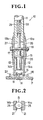
- a parts applying apparatus 10 which essentially comprises a reciprocating ram 11, a punch 12 secured concentrically to the ram 11, a punch holder 13 slidably accommodating the punch 12 and a parts gripper 14 comprising a pair of sleeves 14a and 14b slidably fitted around the periphery of the lower portion of the ram 11.
- the punch 12 has an annular flange 15 secured to the lower end of the ram 11 and a domed bottom 16 configured to snugly fit with a complimentarily shaped button or like parts.
- the ram 11 has an elongate axial slot 26 through which is extended the bolt 17 that holds the parts gripper 14 against the ram 11.
- a push pin 27 coaxial with the ram 11 has its upper end connected to a coil spring 28 accommodated in a bore 29 formed in the ram 11 and its lower end urged by the spring 28 into abutting engagement with the bolt 17.
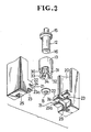
- FIG. 3 shows the punch holder 13 as one cylindrically formed to receive slidably therein the punch 12 and having downwardly projecting lugs 30 - 33 circumferentially equally spaced apart, each of which lugs has an inwardly directed recess 34 for releasably receiving the periphery of a button B.
- the lugs 30 and 32 which are disposed diametrically across the punch holder 13, are dimensioned to fit into the vertical slits 25 in the respective sleeves 14a, 14b.
- An elastic member 35 such as of rubber, spring and the like is interposed between the upper end surface of the punch holder 13 and the lower surface of the flange 15 of the punch 12.
- the apparatus 10 is illustrated for use in clinching the button B with a retainer tack R underlying a strip of fabric F.
- the ram 11 is lowered with the button B placed in the pocket 24 of the parts gripper 14 until the lower end of the gripper 14 reaches the fabric F.
- the punch 12 and its holder 13 continue to descend with the ram 11 until the diametrically opposed lugs 30 and 32 enter and fit in the vertical slits 25 in the respective sleeves 14a and 14b, when the button B has its periphery received in the pocket 24 in the punch holder 13.
- the button B As the button B is forced down by the punch holder 13, it slides down the inclined upper surfaces 23′ of the lower gripping jaws 23, causing the opposed sleeves 14a and 14b to partly spread or move apart away from the punch holder 13 in particular in the direction of the arrow as shown in Figure 4, until the lower end of the punch holder 13 reaches and stops at the surface of the fabric F.
- the punch 12 continues to descend until its domed bottom 16 engages the button B and forces the same into coupling engagement with the retainer tack R across the fabric F as shown in Figure 6, whereupon the sleeves 14a and 14b are retracted by the tention of the springs 19a and 19b and re-engaged with the punch holder 13 and the ram 11.
Landscapes
- Engineering & Computer Science (AREA)
- Mechanical Engineering (AREA)
- Textile Engineering (AREA)
- Treatment Of Fiber Materials (AREA)
- Press Drives And Press Lines (AREA)
- Mounting, Exchange, And Manufacturing Of Dies (AREA)
- Footwear And Its Accessory, Manufacturing Method And Apparatuses (AREA)
- Labeling Devices (AREA)
Abstract
Description
- This invention relates to an apparatus for applying fastening parts such as buttons, rivets, hooks and the like onto articles such as garment fabrics.
- A typical prior art apparatus of the kind above described is disclosed for example in Japanese Laid-Open Patent Publication No. 52-13943, the disclosed apparatus comprising a reciprocating ram, a punch cooperating therewith in clamping parts such as buttons in place on a garment fabric and a gripper adapted to releasably hold the parts in position. The punch is provided at its lower end with four projecting lugs for supporting the parts thereon until the latter are clamped onto the fabric, in which instance the projecting lugs are brought into severe pressure contact with the fabric, resulting in undesirable impact marks on the fabric.
- The present invention seeks to provide a parts applying apparatus for applying fastening parts onto garment fabrics which incorporates structural features enabling the parts to be held in the proper position and clamped in place on the fabric firmly and yet without leaving any pressure impact marks on the fabric.
- The above and other objects of the present invention will be better understood from the following detailed description taken in conjunction with the accompanying drawings.
- According to the invention, a parts applying apparatus comprises: a reciprocating ram; a punch concentrically secured to said ram and having an annular flange; a punch holder slidably accommodating said punch and having a plurality of downwardly projecting lugs adapted to releasably receive fastening parts for attachment to a fabric; a parts gripper comprising a pair of sleeves slidably fitted around said ram, each of said sleeves having a pair of upper and lower gripping jaws defining therebetween a transverse pocket for releasably receiving said parts and a vertical slit extending through said jaws for receiving said projecting lugs; and an elastic member interposed between said punch holder and said annular flange.
- Many other advantages and features of the present invention will become manifest to those versed in the art upon making reference to the detailed description and the accompanying sheets of drawings in which preferred structural embodiments incorporating the principles of the present invention are shown by way of example.
- Figure 1 is an elevational, partly sectional, view of a parts applying apparatus embodying the invention;
- Figure 2 is a cross-sectional view taken on the line II - II of Figure 1;
- Figure 3 is a fragmentary perspective view of the apparatus of Figure 1;
- Figure 4 is a view similar to Figure 1 but showing the apparatus with a button about to be released;
- Figure 5 is a cross-sectional view taken on the line V - V of Figure 4; and
- Figure 6 is a view similar to Figure 4 but showing the button clamped in place on the fabric.
- Referring now to the drawings and Figure 1, in particular, there is shown a
parts applying apparatus 10 which essentially comprises areciprocating ram 11, apunch 12 secured concentrically to theram 11, apunch holder 13 slidably accommodating thepunch 12 and a parts gripper 14 comprising a pair ofsleeves ram 11. - The
punch 12 has anannular flange 15 secured to the lower end of theram 11 and adomed bottom 16 configured to snugly fit with a complimentarily shaped button or like parts. - The pair of
sleeves bolt 17 and anut 18 and slidably engaged with the annular peripheral wall of the lower portion of theram 11. A pair ofarcuate leaf springs sleeves ram 11 and thepunch holder 13. - As shown in Figure 3, the
sleeves ram 11 and each have anelongate slot 20 surrounding theram 11. Each of thesleeves lower gripping jaws pocket 24 for releasably receiving therein a button or other parts. Each of thelower jaws 23 has itsupper surface 23′ slightly inclined downwardly for purposes later to be described. A vertical throughslit 25 is formed through the upper andlower jaws slot 20 for purposes hereafter to be described. - The
ram 11 has an elongateaxial slot 26 through which is extended thebolt 17 that holds the parts gripper 14 against theram 11. Apush pin 27 coaxial with theram 11 has its upper end connected to acoil spring 28 accommodated in abore 29 formed in theram 11 and its lower end urged by thespring 28 into abutting engagement with thebolt 17. - Reference back to Figure 3 shows the
punch holder 13 as one cylindrically formed to receive slidably therein thepunch 12 and having downwardly projecting lugs 30 - 33 circumferentially equally spaced apart, each of which lugs has an inwardly directedrecess 34 for releasably receiving the periphery of a button B. Thelugs 30 and 32, which are disposed diametrically across thepunch holder 13, are dimensioned to fit into thevertical slits 25 in therespective sleeves - An
elastic member 35 such as of rubber, spring and the like is interposed between the upper end surface of thepunch holder 13 and the lower surface of theflange 15 of thepunch 12. - The
apparatus 10 according to the invention is illustrated for use in clinching the button B with a retainer tack R underlying a strip of fabric F. In the operation of theapparatus 10, theram 11 is lowered with the button B placed in thepocket 24 of the parts gripper 14 until the lower end of the gripper 14 reaches the fabric F. While the gripper 14 is held in abutting engagement with the fabric F, thepunch 12 and itsholder 13 continue to descend with theram 11 until the diametrically opposedlugs 30 and 32 enter and fit in thevertical slits 25 in therespective sleeves pocket 24 in thepunch holder 13. As the button B is forced down by thepunch holder 13, it slides down the inclinedupper surfaces 23′ of thelower gripping jaws 23, causing theopposed sleeves punch holder 13 in particular in the direction of the arrow as shown in Figure 4, until the lower end of thepunch holder 13 reaches and stops at the surface of the fabric F. Thepunch 12 continues to descend until itsdomed bottom 16 engages the button B and forces the same into coupling engagement with the retainer tack R across the fabric F as shown in Figure 6, whereupon thesleeves springs punch holder 13 and theram 11. - In the parts applying operation above described, the impact pressure exerted by the
punch holder 13 upon the fabric F is reduced to an absolute minimum on account of the presence of theelastic member 35 which is interposed between thepunch holder 13 and theflange 15 of thepunch 12 and which serves to absorb part of the stroke pressure of theram 11, thus leaving substantially no pressure marks on the fabric F. - Another advantage of the
apparatus 10 according to the invention, the button B can be retained in its proper horizontal position throughout the clamping operation by the projecting lugs 30 - 33 of thepunch holder 13 which are located in advance of thepunch 12 until the latter engages the button B.
Claims (7)
Applications Claiming Priority (2)
| Application Number | Priority Date | Filing Date | Title |
|---|---|---|---|
| JP61408/88 | 1988-05-09 | ||
| JP1988061408U JPH0527459Y2 (en) | 1988-05-09 | 1988-05-09 |
Publications (2)
| Publication Number | Publication Date |
|---|---|
| EP0341655A1 true EP0341655A1 (en) | 1989-11-15 |
| EP0341655B1 EP0341655B1 (en) | 1992-08-05 |
Family
ID=13170275
Family Applications (1)
| Application Number | Title | Priority Date | Filing Date |
|---|---|---|---|
| EP19890108315 Expired - Lifetime EP0341655B1 (en) | 1988-05-09 | 1989-05-09 | Parts applying apparatus |
Country Status (5)
| Country | Link |
|---|---|
| US (1) | US4962875A (en) |
| EP (1) | EP0341655B1 (en) |
| JP (1) | JPH0527459Y2 (en) |
| DE (1) | DE68902352T2 (en) |
| HK (1) | HK194795A (en) |
Cited By (1)
| Publication number | Priority date | Publication date | Assignee | Title |
|---|---|---|---|---|
| US6263561B1 (en) | 1992-04-03 | 2001-07-24 | Multifastener Corporation | Fastener retaining device for assembly parts |
Families Citing this family (4)
| Publication number | Priority date | Publication date | Assignee | Title |
|---|---|---|---|---|
| CA2758874C (en) | 2009-05-15 | 2014-11-25 | Fyi Design Dept. Ltd. | Methods and apparatus for affixing hardware to garments |
| WO2011077571A1 (en) * | 2009-12-25 | 2011-06-30 | Ykk株式会社 | Upper die for mounting button |
| WO2015035257A2 (en) | 2013-09-05 | 2015-03-12 | Boa Technology Inc. | Alternative lacing guides for tightening mechanisms and methods therefor |
| KR102552961B1 (en) | 2016-08-02 | 2023-07-10 | 보아 테크놀러지, 인크. | Tension member guides of a lacing system |
Citations (2)
| Publication number | Priority date | Publication date | Assignee | Title |
|---|---|---|---|---|
| US3964661A (en) * | 1974-10-23 | 1976-06-22 | Textron, Inc. | Apparatus for attaching pronged and mating elements to articles |
| EP0135885A2 (en) * | 1983-09-19 | 1985-04-03 | Nippon Notion Kogyo Co., Ltd. | Apparatus for attaching pairs of fastener elements onto garnment fabrics |
Family Cites Families (9)
| Publication number | Priority date | Publication date | Assignee | Title |
|---|---|---|---|---|
| US3503549A (en) * | 1967-09-29 | 1970-03-31 | Olin Mathieson | Muzzle bushing for piston-type power-actuated tool |
| CA1038826A (en) * | 1975-07-18 | 1978-09-19 | Textron Inc. | Apparatus for attaching pronged and mating elements to articles |
| US4239143A (en) * | 1979-05-21 | 1980-12-16 | Olin Corporation | Driver assembly for small-diameter fasteners |
| JPS58123036A (en) * | 1982-01-18 | 1983-07-22 | Mitsubishi Electric Corp | Device for controlling intake air volume for air conditioner |
| JPS6032746A (en) * | 1983-08-02 | 1985-02-19 | Sagami Chem Res Center | Production of benzoquinone compound |
| JPH0232658Y2 (en) * | 1985-08-13 | 1990-09-04 | ||
| JPH0232662Y2 (en) * | 1985-11-12 | 1990-09-04 | ||
| JPS6324229U (en) * | 1986-07-30 | 1988-02-17 | ||
| GB8705130D0 (en) * | 1987-03-05 | 1987-04-08 | Francis T E | Automatic nailer system |
-
1988
- 1988-05-09 JP JP1988061408U patent/JPH0527459Y2/ja not_active Expired - Lifetime
-
1989
- 1989-05-04 US US07/347,013 patent/US4962875A/en not_active Expired - Fee Related
- 1989-05-09 EP EP19890108315 patent/EP0341655B1/en not_active Expired - Lifetime
- 1989-05-09 DE DE8989108315T patent/DE68902352T2/en not_active Expired - Lifetime
-
1995
- 1995-12-28 HK HK194795A patent/HK194795A/en not_active IP Right Cessation
Patent Citations (2)
| Publication number | Priority date | Publication date | Assignee | Title |
|---|---|---|---|---|
| US3964661A (en) * | 1974-10-23 | 1976-06-22 | Textron, Inc. | Apparatus for attaching pronged and mating elements to articles |
| EP0135885A2 (en) * | 1983-09-19 | 1985-04-03 | Nippon Notion Kogyo Co., Ltd. | Apparatus for attaching pairs of fastener elements onto garnment fabrics |
Cited By (1)
| Publication number | Priority date | Publication date | Assignee | Title |
|---|---|---|---|---|
| US6263561B1 (en) | 1992-04-03 | 2001-07-24 | Multifastener Corporation | Fastener retaining device for assembly parts |
Also Published As
| Publication number | Publication date |
|---|---|
| DE68902352D1 (en) | 1992-09-10 |
| EP0341655B1 (en) | 1992-08-05 |
| HK194795A (en) | 1996-01-05 |
| JPH01164727U (en) | 1989-11-17 |
| US4962875A (en) | 1990-10-16 |
| DE68902352T2 (en) | 1992-12-24 |
| JPH0527459Y2 (en) | 1993-07-13 |
Similar Documents
| Publication | Publication Date | Title |
|---|---|---|
| US4436238A (en) | Apparatus for attaching fastener elements onto a garment | |
| US4101064A (en) | Slug riveting apparatus | |
| EP0341655B1 (en) | Parts applying apparatus | |
| JPS61167005A (en) | Reveting press for attaching restraint function part, especially press bottom part to holding strip piece such as clothing | |
| EP0222595B1 (en) | Punch assembly for garment fastener attaching apparatus | |
| KR900004873B1 (en) | Button collet having a domed cap and method and apparatus for making the same | |
| US4659001A (en) | Machine for applying articles of hardware to tensioned textile materials | |
| EP0135885B1 (en) | Apparatus for attaching pairs of fastener elements onto garnment fabrics | |
| EP0131180B1 (en) | Apparatus for assembling buttons | |
| EP0136633B1 (en) | Apparatus for assembling a pair of fastener elements | |
| JPH0761287B2 (en) | How to assemble the leaf spring of the slider with automatic stop device for slide fastener | |
| CA1303558C (en) | Punch assembly | |
| EP0212395B1 (en) | Button holder/die assembly in a device for attaching buttons to sheet members | |
| EP0212675B1 (en) | Apparatus for removing fastener members from a garment fabric | |
| CA2194260C (en) | Fastener installation head | |
| DE3265187D1 (en) | Blind-rivet tool | |
| CA2022978C (en) | Fastener installation apparatus | |
| JP2003103335A (en) | Connecting method for two or more constitutional members using rivet, and device for conducting the method | |
| JPH0683936B2 (en) | Automatic device for snap ring | |
| JPS6241934Y2 (en) | ||
| SU1097485A1 (en) | Device for setting long rings | |
| US2411914A (en) | Fastener | |
| ES2136779T3 (en) | DEVICE FOR DEEP STUFFING OF SHEET METAL. | |
| JPH06154903A (en) | Piercing machine | |
| PL63503B1 (en) |
Legal Events
| Date | Code | Title | Description |
|---|---|---|---|
| PUAI | Public reference made under article 153(3) epc to a published international application that has entered the european phase |
Free format text: ORIGINAL CODE: 0009012 |
|
| AK | Designated contracting states |
Kind code of ref document: A1 Designated state(s): DE FR GB IT |
|
| 17P | Request for examination filed |
Effective date: 19900215 |
|
| 17Q | First examination report despatched |
Effective date: 19910529 |
|
| GRAA | (expected) grant |
Free format text: ORIGINAL CODE: 0009210 |
|
| AK | Designated contracting states |
Kind code of ref document: B1 Designated state(s): DE FR GB IT |
|
| ITF | It: translation for a ep patent filed | ||
| ET | Fr: translation filed | ||
| REF | Corresponds to: |
Ref document number: 68902352 Country of ref document: DE Date of ref document: 19920910 |
|
| RIN2 | Information on inventor provided after grant (corrected) |
Free format text: SODENO, TOSHIAKI |
|
| PLBE | No opposition filed within time limit |
Free format text: ORIGINAL CODE: 0009261 |
|
| STAA | Information on the status of an ep patent application or granted ep patent |
Free format text: STATUS: NO OPPOSITION FILED WITHIN TIME LIMIT |
|
| 26N | No opposition filed | ||
| ITPR | It: changes in ownership of a european patent |
Owner name: CAMBIO RAGIONE SOCIALE;YKK CORPORATION |
|
| REG | Reference to a national code |
Ref country code: FR Ref legal event code: CD |
|
| PGFP | Annual fee paid to national office [announced via postgrant information from national office to epo] |
Ref country code: DE Payment date: 19950630 Year of fee payment: 7 |
|
| PGFP | Annual fee paid to national office [announced via postgrant information from national office to epo] |
Ref country code: FR Payment date: 19960320 Year of fee payment: 8 |
|
| PGFP | Annual fee paid to national office [announced via postgrant information from national office to epo] |
Ref country code: GB Payment date: 19960430 Year of fee payment: 8 |
|
| PG25 | Lapsed in a contracting state [announced via postgrant information from national office to epo] |
Ref country code: DE Effective date: 19970201 |
|
| PG25 | Lapsed in a contracting state [announced via postgrant information from national office to epo] |
Ref country code: GB Effective date: 19970509 |
|
| GBPC | Gb: european patent ceased through non-payment of renewal fee |
Effective date: 19970509 |
|
| PG25 | Lapsed in a contracting state [announced via postgrant information from national office to epo] |
Ref country code: FR Free format text: LAPSE BECAUSE OF NON-PAYMENT OF DUE FEES Effective date: 19980130 |
|
| REG | Reference to a national code |
Ref country code: FR Ref legal event code: ST |
|
| PG25 | Lapsed in a contracting state [announced via postgrant information from national office to epo] |
Ref country code: IT Free format text: LAPSE BECAUSE OF NON-PAYMENT OF DUE FEES;WARNING: LAPSES OF ITALIAN PATENTS WITH EFFECTIVE DATE BEFORE 2007 MAY HAVE OCCURRED AT ANY TIME BEFORE 2007. THE CORRECT EFFECTIVE DATE MAY BE DIFFERENT FROM THE ONE RECORDED. Effective date: 20050509 |