EP0341321A2 - Sperrvorrichtung - Google Patents
Sperrvorrichtung Download PDFInfo
- Publication number
- EP0341321A2 EP0341321A2 EP87850252A EP87850252A EP0341321A2 EP 0341321 A2 EP0341321 A2 EP 0341321A2 EP 87850252 A EP87850252 A EP 87850252A EP 87850252 A EP87850252 A EP 87850252A EP 0341321 A2 EP0341321 A2 EP 0341321A2
- Authority
- EP
- European Patent Office
- Prior art keywords
- ring
- cavity
- recess
- locking device
- sleeve
- Prior art date
- Legal status (The legal status is an assumption and is not a legal conclusion. Google has not performed a legal analysis and makes no representation as to the accuracy of the status listed.)
- Withdrawn
Links
- 238000003754 machining Methods 0.000 claims abstract description 7
- 230000002093 peripheral effect Effects 0.000 claims description 30
- 230000003247 decreasing effect Effects 0.000 claims description 3
- 230000001154 acute effect Effects 0.000 claims description 2
- 230000000149 penetrating effect Effects 0.000 claims description 2
- 208000032826 Ring chromosome 3 syndrome Diseases 0.000 description 11
- 239000000306 component Substances 0.000 description 7
- 230000007423 decrease Effects 0.000 description 2
Images


Classifications
-
- F—MECHANICAL ENGINEERING; LIGHTING; HEATING; WEAPONS; BLASTING
- F16—ENGINEERING ELEMENTS AND UNITS; GENERAL MEASURES FOR PRODUCING AND MAINTAINING EFFECTIVE FUNCTIONING OF MACHINES OR INSTALLATIONS; THERMAL INSULATION IN GENERAL
- F16D—COUPLINGS FOR TRANSMITTING ROTATION; CLUTCHES; BRAKES
- F16D1/00—Couplings for rigidly connecting two coaxial shafts or other movable machine elements
- F16D1/10—Quick-acting couplings in which the parts are connected by simply bringing them together axially
- F16D1/104—Quick-acting couplings in which the parts are connected by simply bringing them together axially having retaining means rotating with the coupling and acting only by friction
Definitions
- the present invention relates to a locking device for machining tools such as grinders, saw blades and the like on a drive means such as the shaft of a motor.
- machining tools such as grinders, saw blades and the like on a drive means such as the shaft of a motor.
- Such machining tools have hitherto been secured to the shaft by screw joints, for instance. Exchanging the such tools is thus extremely time-consuming.
- the object of the present invention is to reduce the time required for exchanging tools to an absolute minimum. This is enabled by attaching a unit with an internal envelope surface to the drive shaft of a machining tool. This surface is intended to cooperate with the outer envelope surface of a body to be secured to the drive shaft.
- the inner surface is also provided with a number of cavities, each cavity being big enough to allow a pressure-actuated body to be caused to partially protrude through the associated recess.
- Each pressure-actuated body in the unit is movable in a cavity in such a way that when the body with the outer envelope surface is applied to the inner envelope surface, the pressure-actuated body will acquire a component of movement in a direction coinciding with the direction of application of the body with the outer envelope surface.
- the pressure-actuated body also acquires an outwardly directed radial component of movement. The direction of this latter component will be reverse if an attempt is made to remove the body with the external envelope surface.
- said member consists of a ring penetrating into the inner peripheral surface along its periphery, having a peripheral surface which partially closes the open end of each cavity.
- the peripheral surface of said ring is such that when the ring is turned about its central axis, the pressure-actuated body can be accorded a movement against the pressure-actuation so that the body leaves the recess into which it is being forced.
- the peripheral surface of the ring may be provided with a radial groove which preferably decreases in depth from its mid-point.
- additional means are provided to continuously strive to turn the ring to a position in which the pressure-actuated bodies are able to protrude into the respective recesses, thus effecting a locking function.
- Said means consist of radial grooves in the peripheral surface of the ring, each groove decreasing in depth from its mid-point, and each groove cooperating with a body pressure-influenced in a direction towards the groove, this direction being perpendicular to the peripheral surface. Bodies of this type are suitably arranged in the unit with the internal peripheral surface.
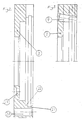
- 11 is the drive shaft of a motor of optional type.
- the shaft 11 is provided with a shaft extension 12, the shaft end 13 being tapped to cooperate with a nut 14.
- the shaft extension 12 is smaller in diameter than the shaft 11, thus providing a contact surface at the shaft 11 around the shaft extension 12.
- a sleeve 2 is applied on the shaft extension 12, one end abutting the contact surface of the shaft 11 and is kept clamped against this surface by the nut 14.
- a peripheral ring is secured to the sleeve 2 by means of one or more screws 15 passing through holes 19 in the peripheral ring.
- the peripheral ring 3 has an inner envelope surface clearly visible in Figure 2, where the left part of the envelope surface shall cooperate with part of the sleeve 2, and the following part of the envelope surface is intended to cooperate with the external envelope surface of a sleeve 1. These opposing envelope surfaces are intended to abut or substantially abut each other.
- the peripheral ring 3 is provided with a plurality of cavities 9. The central axis of each cavity lies in a plane passing through the central axis of the peripheral ring 3.
- each cavity 9 forms an acute angle with the central axis of the peripheral ring 3.
- Each cavity has a bottom and, in contact with the bottom, a helical spring 7. The other end of the spring 7 is in contact with a locking ball 6, the diameter of which corresponds substantially to that of the cavity.
- Each cavity has a recess in the envelope surface which is to cooperate with the envelope surface of the outer sleeve 1. This recess is smaller than the diameter of the ball 6.
- each cavity 9 is sealed by the grooved ring 8.
- the ring is provided with a radial groove 10 for each ball 6 in a cavity 9.
- the groove is shown here with a purely triangular cross section. However, it is evident that the groove may be designed with decreasing depth from its mid-point.
- the grooved ring 8 can be turned about its central axis by means of two manually operated protrusions 16 and 17.
- the balls 6 will either be in contact with the flat peripheral surface of the grooved ring 8, or they will be in contact with the walls of a groove 10. in the latter case the ball 6 protrudes out of the recess in the inner envelope surface of the peripheral ring 3. If, however, the ball is in contact with the peripheral surface of the ring, it will be pushed aside from said recess.
- the body 1 is assumed to have a cylindrical outer surface, but obviously the surface could form a polygon. This also applies to the inner envelope surface of the peripheral ring 3.
- a machining tool such as a grinder or saw blade is attached to the sleeve or body 1.
- the sleeve 1 has a peripheral flange provided with a number of holes for fingers 4 arranged in the peripheral ring 3.
- the means described above functions as follows: It is assumed that the sleeve 1 with machining tool is to be attached to the shaft 11, the sleeve 1 being applied on the sleeve 2 and turned until the fingers 4 fit into holes in the flange of the sleeve 1. it is also assumed that the position of the grooved ring is such that each ball 6 is in a groove 10. A part of the ball 6 thus protudes out through the recess in the inner envelope surface. As mentioned earlier, the recess has smaller diameter than the ball 6 and the ball cannot therefore pass fully out of the recess.
- the ball 6 Upon contact with the outer envelope surface of the sleeve 1, the ball 6 acquires components of movement in both axial and radially outward direction, and the sleeve can therefore be placed in the rest position indicated in the drawing. It is impossible to remove the tool with the grooved ring 8 in this position inasmuch as, if an attempt is made to remove the sleeve 1, each ball will acquire an axial and a radially inwardly directed component of movement. The latter component of movement locks the sleeve 1 so tightly to the peripheral ring 3 that forces in excess of 1 ton are required to remove the sleeve from the ring 3.
- a means is also desirable which always strives to keep the grooved ring in such a position that a ball 6 is located in the associated groove 10.
- the grooved ring 8 is provided with a number of grooves 18 cooperating with a spring-actuated ball, the ball cooperating only with the groove 18 and being accorded a force perpendicular to the grooved peripheral surface of the ring.
- Each groove 18 decreases in depth from its mid-point, its cross section suitably being triangular.
- Each ball cooperating with the last-mentioned grooves strives to turn the ring 8 so that the ball reaches the bottom of the groove. When this occurs, each ball 6 will also be at the bottom of the respective groove 10.
Landscapes
- Engineering & Computer Science (AREA)
- General Engineering & Computer Science (AREA)
- Mechanical Engineering (AREA)
- Finish Polishing, Edge Sharpening, And Grinding By Specific Grinding Devices (AREA)
Priority Applications (1)
| Application Number | Priority Date | Filing Date | Title |
|---|---|---|---|
| EP87850252A EP0341321A3 (de) | 1987-11-06 | 1987-11-06 | Sperrvorrichtung |
Applications Claiming Priority (1)
| Application Number | Priority Date | Filing Date | Title |
|---|---|---|---|
| EP87850252A EP0341321A3 (de) | 1987-11-06 | 1987-11-06 | Sperrvorrichtung |
Publications (2)
| Publication Number | Publication Date |
|---|---|
| EP0341321A2 true EP0341321A2 (de) | 1989-11-15 |
| EP0341321A3 EP0341321A3 (de) | 1989-11-29 |
Family
ID=8198489
Family Applications (1)
| Application Number | Title | Priority Date | Filing Date |
|---|---|---|---|
| EP87850252A Withdrawn EP0341321A3 (de) | 1987-11-06 | 1987-11-06 | Sperrvorrichtung |
Country Status (1)
| Country | Link |
|---|---|
| EP (1) | EP0341321A3 (de) |
Cited By (1)
| Publication number | Priority date | Publication date | Assignee | Title |
|---|---|---|---|---|
| EP0753680A1 (de) * | 1995-07-14 | 1997-01-15 | MAPAL Fabrik für Präzisionswerkzeuge Dr. Kress KG | Verbindungsstelle |
Family Cites Families (3)
| Publication number | Priority date | Publication date | Assignee | Title |
|---|---|---|---|---|
| US2874814A (en) * | 1957-05-01 | 1959-02-24 | Da Ruben L Beck | Free locking wheel hub |
| GB1340342A (en) * | 1970-04-10 | 1973-12-12 | Secr Defence | Fastening device |
| DE3228889A1 (de) * | 1982-08-03 | 1984-02-09 | Audi Nsu Auto Union Ag, 7107 Neckarsulm | Kupplung zum steckverbinden einer welle mit einem teil mit einer axialen ausnehmung |
-
1987
- 1987-11-06 EP EP87850252A patent/EP0341321A3/de not_active Withdrawn
Cited By (2)
| Publication number | Priority date | Publication date | Assignee | Title |
|---|---|---|---|---|
| EP0753680A1 (de) * | 1995-07-14 | 1997-01-15 | MAPAL Fabrik für Präzisionswerkzeuge Dr. Kress KG | Verbindungsstelle |
| US5810506A (en) * | 1995-07-14 | 1998-09-22 | Mapal Fabrik Fur Prazisionswerkzeuge Dr. Kress Kg | Device for coupling tool parts |
Also Published As
| Publication number | Publication date |
|---|---|
| EP0341321A3 (de) | 1989-11-29 |
Similar Documents
| Publication | Publication Date | Title |
|---|---|---|
| US6254303B1 (en) | Quick-release connector and methods therefore | |
| US4006993A (en) | Shaft mounting arrangement | |
| KR890009540A (ko) | 포어터블 공작 기구 | |
| CN1090629A (zh) | 用以连接至少两个构件的装置 | |
| WO1988009444A1 (en) | A fastening device and a tool for securing the same | |
| WO2005032769A1 (en) | Power tool with angle drive and pinion adjustment | |
| US5216941A (en) | Tool for securing a fastening device | |
| US4948320A (en) | Preventing movement of an article along a shaft or bore | |
| EP0691184B1 (de) | Werkzeug zum Entfernen von Flanchbefestigungsmitteln | |
| US4692078A (en) | Nut device having automatic positive locking | |
| US4604008A (en) | Metal working machine having polygon tool support bar | |
| EP0341321A2 (de) | Sperrvorrichtung | |
| US4666353A (en) | Eccentricity adjustment device | |
| US6067713A (en) | Method of manufacturing a rack and pinion steering gear | |
| AU7702494A (en) | Locking device for use with shafts or tubes | |
| CA1305892C (en) | Friction device for the setting process in projectile fuses | |
| US3879046A (en) | Rotary tool holders | |
| US4968175A (en) | Torque transmitting assembly | |
| US4620459A (en) | Speed socket wrench | |
| US3782742A (en) | Three jaw chuck application | |
| SU1161256A1 (ru) | Механизм перемещени зажимного элемента,например,пиноли задней бабки металлорежущего станка | |
| US5069096A (en) | Advanced spider fixture | |
| CA2487237A1 (en) | Cylindric drum with sanding elements | |
| KR200468660Y1 (ko) | 인덱스 드라이브 장치 | |
| SU1249213A1 (ru) | Быстродействующа гайка |
Legal Events
| Date | Code | Title | Description |
|---|---|---|---|
| PUAI | Public reference made under article 153(3) epc to a published international application that has entered the european phase |
Free format text: ORIGINAL CODE: 0009012 |
|
| PUAL | Search report despatched |
Free format text: ORIGINAL CODE: 0009013 |
|
| 17P | Request for examination filed |
Effective date: 19870831 |
|
| AK | Designated contracting states |
Kind code of ref document: A2 Designated state(s): AT BE CH DE ES FR GB GR IT LI LU NL SE |
|
| AK | Designated contracting states |
Kind code of ref document: A3 Designated state(s): AT BE CH DE ES FR GB GR IT LI LU NL SE |
|
| 17Q | First examination report despatched |
Effective date: 19901008 |
|
| STAA | Information on the status of an ep patent application or granted ep patent |
Free format text: STATUS: THE APPLICATION HAS BEEN WITHDRAWN |
|
| 18W | Application withdrawn |
Withdrawal date: 19910924 |
|
| R18W | Application withdrawn (corrected) |
Effective date: 19910924 |
|
| APAF | Appeal reference modified |
Free format text: ORIGINAL CODE: EPIDOSCREFNE |
|
| RIN1 | Information on inventor provided before grant (corrected) |
Inventor name: KARLSSON, BERTIL |