EP0341309B1 - Porous polypropylene membrane and process for its production - Google Patents
Porous polypropylene membrane and process for its production Download PDFInfo
- Publication number
- EP0341309B1 EP0341309B1 EP88901092A EP88901092A EP0341309B1 EP 0341309 B1 EP0341309 B1 EP 0341309B1 EP 88901092 A EP88901092 A EP 88901092A EP 88901092 A EP88901092 A EP 88901092A EP 0341309 B1 EP0341309 B1 EP 0341309B1
- Authority
- EP
- European Patent Office
- Prior art keywords
- hollow fiber
- polypropylene
- membrane
- range
- fiber membrane
- Prior art date
- Legal status (The legal status is an assumption and is not a legal conclusion. Google has not performed a legal analysis and makes no representation as to the accuracy of the status listed.)
- Expired - Lifetime
Links
- 239000012528 membrane Substances 0.000 title claims abstract description 251
- -1 polypropylene Polymers 0.000 title claims abstract description 171
- 239000004743 Polypropylene Substances 0.000 title claims abstract description 166
- 229920001155 polypropylene Polymers 0.000 title claims abstract description 166
- 238000000034 method Methods 0.000 title claims description 44
- 238000004519 manufacturing process Methods 0.000 title claims description 28
- 230000008569 process Effects 0.000 title description 3
- 210000004072 lung Anatomy 0.000 claims abstract description 73
- 238000001816 cooling Methods 0.000 claims abstract description 72
- 239000007789 gas Substances 0.000 claims abstract description 47
- 239000011148 porous material Substances 0.000 claims abstract description 36
- 239000007790 solid phase Substances 0.000 claims abstract description 27
- MYMOFIZGZYHOMD-UHFFFAOYSA-N Dioxygen Chemical compound O=O MYMOFIZGZYHOMD-UHFFFAOYSA-N 0.000 claims abstract description 17
- 229910001882 dioxygen Inorganic materials 0.000 claims abstract description 16
- 230000004907 flux Effects 0.000 claims abstract description 14
- 239000012071 phase Substances 0.000 claims abstract description 9
- 229920002545 silicone oil Polymers 0.000 claims abstract description 9
- 239000012510 hollow fiber Substances 0.000 claims description 234
- 210000004369 blood Anatomy 0.000 claims description 64
- 239000008280 blood Substances 0.000 claims description 64
- 239000012766 organic filler Substances 0.000 claims description 59
- 239000007788 liquid Substances 0.000 claims description 54
- 239000002245 particle Substances 0.000 claims description 34
- QVGXLLKOCUKJST-UHFFFAOYSA-N atomic oxygen Chemical compound [O] QVGXLLKOCUKJST-UHFFFAOYSA-N 0.000 claims description 23
- 239000000835 fiber Substances 0.000 claims description 23
- 239000001301 oxygen Substances 0.000 claims description 23
- 229910052760 oxygen Inorganic materials 0.000 claims description 23
- 239000003795 chemical substances by application Substances 0.000 claims description 22
- 229940057995 liquid paraffin Drugs 0.000 claims description 18
- 238000009987 spinning Methods 0.000 claims description 13
- 239000000126 substance Substances 0.000 claims description 13
- 238000000605 extraction Methods 0.000 claims description 10
- 238000002156 mixing Methods 0.000 claims description 10
- 229920001223 polyethylene glycol Polymers 0.000 claims description 7
- 238000002844 melting Methods 0.000 claims description 6
- 230000008018 melting Effects 0.000 claims description 6
- 239000011369 resultant mixture Substances 0.000 claims description 6
- 238000002425 crystallisation Methods 0.000 claims description 5
- 230000008025 crystallization Effects 0.000 claims description 5
- 238000007599 discharging Methods 0.000 claims description 5
- 210000002381 plasma Anatomy 0.000 abstract description 35
- 239000000203 mixture Substances 0.000 abstract description 20
- 239000012530 fluid Substances 0.000 abstract description 11
- 230000035699 permeability Effects 0.000 abstract description 10
- 239000012298 atmosphere Substances 0.000 abstract description 5
- XLYOFNOQVPJJNP-UHFFFAOYSA-N water Substances O XLYOFNOQVPJJNP-UHFFFAOYSA-N 0.000 abstract description 5
- 239000000945 filler Substances 0.000 abstract description 3
- 239000012188 paraffin wax Substances 0.000 abstract description 2
- 239000004721 Polyphenylene oxide Substances 0.000 abstract 1
- 239000008187 granular material Substances 0.000 abstract 1
- 238000004898 kneading Methods 0.000 abstract 1
- 239000002667 nucleating agent Substances 0.000 abstract 1
- 229920000570 polyether Polymers 0.000 abstract 1
- 239000011800 void material Substances 0.000 abstract 1
- CURLTUGMZLYLDI-UHFFFAOYSA-N Carbon dioxide Chemical compound O=C=O CURLTUGMZLYLDI-UHFFFAOYSA-N 0.000 description 26
- 239000001569 carbon dioxide Substances 0.000 description 13
- 229910002092 carbon dioxide Inorganic materials 0.000 description 13
- 230000004087 circulation Effects 0.000 description 12
- 210000000601 blood cell Anatomy 0.000 description 11
- 208000027418 Wounds and injury Diseases 0.000 description 10
- 230000006378 damage Effects 0.000 description 9
- 230000000694 effects Effects 0.000 description 9
- 229920000098 polyolefin Polymers 0.000 description 9
- 238000012546 transfer Methods 0.000 description 9
- 238000010438 heat treatment Methods 0.000 description 8
- 208000014674 injury Diseases 0.000 description 8
- 238000012856 packing Methods 0.000 description 8
- QQONPFPTGQHPMA-UHFFFAOYSA-N propylene Natural products CC=C QQONPFPTGQHPMA-UHFFFAOYSA-N 0.000 description 8
- 125000004805 propylene group Chemical group [H]C([H])([H])C([H])([*:1])C([H])([H])[*:2] 0.000 description 8
- 239000002994 raw material Substances 0.000 description 8
- 239000000306 component Substances 0.000 description 7
- 230000001747 exhibiting effect Effects 0.000 description 7
- 241000283690 Bos taurus Species 0.000 description 6
- 206010018910 Haemolysis Diseases 0.000 description 6
- 230000008588 hemolysis Effects 0.000 description 6
- 235000010356 sorbitol Nutrition 0.000 description 6
- AJDIZQLSFPQPEY-UHFFFAOYSA-N 1,1,2-Trichlorotrifluoroethane Chemical compound FC(F)(Cl)C(F)(Cl)Cl AJDIZQLSFPQPEY-UHFFFAOYSA-N 0.000 description 5
- FBPFZTCFMRRESA-FSIIMWSLSA-N D-Glucitol Natural products OC[C@H](O)[C@H](O)[C@@H](O)[C@H](O)CO FBPFZTCFMRRESA-FSIIMWSLSA-N 0.000 description 5
- 239000003570 air Substances 0.000 description 5
- 238000004382 potting Methods 0.000 description 5
- 239000000600 sorbitol Substances 0.000 description 5
- LFQSCWFLJHTTHZ-UHFFFAOYSA-N Ethanol Chemical compound CCO LFQSCWFLJHTTHZ-UHFFFAOYSA-N 0.000 description 4
- 102000001554 Hemoglobins Human genes 0.000 description 4
- 108010054147 Hemoglobins Proteins 0.000 description 4
- 239000002202 Polyethylene glycol Substances 0.000 description 4
- 230000015556 catabolic process Effects 0.000 description 4
- 150000001875 compounds Chemical class 0.000 description 4
- 239000013078 crystal Substances 0.000 description 4
- 238000006731 degradation reaction Methods 0.000 description 4
- 238000009826 distribution Methods 0.000 description 4
- 229920002379 silicone rubber Polymers 0.000 description 4
- 239000004945 silicone rubber Substances 0.000 description 4
- 239000000243 solution Substances 0.000 description 4
- IJGRMHOSHXDMSA-UHFFFAOYSA-N Atomic nitrogen Chemical compound N#N IJGRMHOSHXDMSA-UHFFFAOYSA-N 0.000 description 3
- OKKJLVBELUTLKV-UHFFFAOYSA-N Methanol Chemical compound OC OKKJLVBELUTLKV-UHFFFAOYSA-N 0.000 description 3
- 230000002950 deficient Effects 0.000 description 3
- 150000008282 halocarbons Chemical class 0.000 description 3
- 229920001519 homopolymer Polymers 0.000 description 3
- 230000001939 inductive effect Effects 0.000 description 3
- 239000000463 material Substances 0.000 description 3
- 229920000642 polymer Polymers 0.000 description 3
- 102000004169 proteins and genes Human genes 0.000 description 3
- 108090000623 proteins and genes Proteins 0.000 description 3
- 229920005989 resin Polymers 0.000 description 3
- 239000011347 resin Substances 0.000 description 3
- 238000000926 separation method Methods 0.000 description 3
- 239000002904 solvent Substances 0.000 description 3
- 241000894007 species Species 0.000 description 3
- XKRFYHLGVUSROY-UHFFFAOYSA-N Argon Chemical compound [Ar] XKRFYHLGVUSROY-UHFFFAOYSA-N 0.000 description 2
- VGGSQFUCUMXWEO-UHFFFAOYSA-N Ethene Chemical compound C=C VGGSQFUCUMXWEO-UHFFFAOYSA-N 0.000 description 2
- 239000005977 Ethylene Substances 0.000 description 2
- XEEYBQQBJWHFJM-UHFFFAOYSA-N Iron Chemical compound [Fe] XEEYBQQBJWHFJM-UHFFFAOYSA-N 0.000 description 2
- UIIMBOGNXHQVGW-UHFFFAOYSA-M Sodium bicarbonate Chemical compound [Na+].OC([O-])=O UIIMBOGNXHQVGW-UHFFFAOYSA-M 0.000 description 2
- 230000002159 abnormal effect Effects 0.000 description 2
- 239000000853 adhesive Substances 0.000 description 2
- WNLRTRBMVRJNCN-UHFFFAOYSA-N adipic acid Chemical compound OC(=O)CCCCC(O)=O WNLRTRBMVRJNCN-UHFFFAOYSA-N 0.000 description 2
- 230000008901 benefit Effects 0.000 description 2
- 230000015572 biosynthetic process Effects 0.000 description 2
- 230000008859 change Effects 0.000 description 2
- 238000001035 drying Methods 0.000 description 2
- 239000011521 glass Substances 0.000 description 2
- 229930195733 hydrocarbon Natural products 0.000 description 2
- 150000002430 hydrocarbons Chemical class 0.000 description 2
- 239000000155 melt Substances 0.000 description 2
- 239000005026 oriented polypropylene Substances 0.000 description 2
- 238000005191 phase separation Methods 0.000 description 2
- 238000007639 printing Methods 0.000 description 2
- FMZUHGYZWYNSOA-VVBFYGJXSA-N (1r)-1-[(4r,4ar,8as)-2,6-diphenyl-4,4a,8,8a-tetrahydro-[1,3]dioxino[5,4-d][1,3]dioxin-4-yl]ethane-1,2-diol Chemical compound C([C@@H]1OC(O[C@@H]([C@@H]1O1)[C@H](O)CO)C=2C=CC=CC=2)OC1C1=CC=CC=C1 FMZUHGYZWYNSOA-VVBFYGJXSA-N 0.000 description 1
- UGCSPKPEHQEOSR-UHFFFAOYSA-N 1,1,2,2-tetrachloro-1,2-difluoroethane Chemical compound FC(Cl)(Cl)C(F)(Cl)Cl UGCSPKPEHQEOSR-UHFFFAOYSA-N 0.000 description 1
- 206010018364 Glomerulonephritis Diseases 0.000 description 1
- LRHPLDYGYMQRHN-UHFFFAOYSA-N N-Butanol Chemical class CCCCO LRHPLDYGYMQRHN-UHFFFAOYSA-N 0.000 description 1
- AMQJEAYHLZJPGS-UHFFFAOYSA-N N-Pentanol Chemical class CCCCCO AMQJEAYHLZJPGS-UHFFFAOYSA-N 0.000 description 1
- 239000004952 Polyamide Substances 0.000 description 1
- 239000004698 Polyethylene Substances 0.000 description 1
- 239000004372 Polyvinyl alcohol Substances 0.000 description 1
- 239000001361 adipic acid Substances 0.000 description 1
- 235000011037 adipic acid Nutrition 0.000 description 1
- 150000001298 alcohols Chemical class 0.000 description 1
- 239000000427 antigen Substances 0.000 description 1
- 102000036639 antigens Human genes 0.000 description 1
- 108091007433 antigens Proteins 0.000 description 1
- 229910052786 argon Inorganic materials 0.000 description 1
- 210000001367 artery Anatomy 0.000 description 1
- 230000017531 blood circulation Effects 0.000 description 1
- 239000012503 blood component Substances 0.000 description 1
- 230000000747 cardiac effect Effects 0.000 description 1
- 238000005266 casting Methods 0.000 description 1
- 229920002301 cellulose acetate Polymers 0.000 description 1
- 238000006243 chemical reaction Methods 0.000 description 1
- 230000000295 complement effect Effects 0.000 description 1
- 238000010276 construction Methods 0.000 description 1
- 230000008602 contraction Effects 0.000 description 1
- 230000006735 deficit Effects 0.000 description 1
- 238000001514 detection method Methods 0.000 description 1
- 229940087101 dibenzylidene sorbitol Drugs 0.000 description 1
- UMNKXPULIDJLSU-UHFFFAOYSA-N dichlorofluoromethane Chemical compound FC(Cl)Cl UMNKXPULIDJLSU-UHFFFAOYSA-N 0.000 description 1
- 229940099364 dichlorofluoromethane Drugs 0.000 description 1
- 125000000118 dimethyl group Chemical group [H]C([H])([H])* 0.000 description 1
- 201000010099 disease Diseases 0.000 description 1
- 208000037265 diseases, disorders, signs and symptoms Diseases 0.000 description 1
- LQZZUXJYWNFBMV-UHFFFAOYSA-N dodecan-1-ol Chemical compound CCCCCCCCCCCCO LQZZUXJYWNFBMV-UHFFFAOYSA-N 0.000 description 1
- 238000000635 electron micrograph Methods 0.000 description 1
- 239000003822 epoxy resin Substances 0.000 description 1
- 210000003743 erythrocyte Anatomy 0.000 description 1
- 239000000284 extract Substances 0.000 description 1
- 238000011049 filling Methods 0.000 description 1
- 238000009472 formulation Methods 0.000 description 1
- 239000001307 helium Substances 0.000 description 1
- 229910052734 helium Inorganic materials 0.000 description 1
- SWQJXJOGLNCZEY-UHFFFAOYSA-N helium atom Chemical compound [He] SWQJXJOGLNCZEY-UHFFFAOYSA-N 0.000 description 1
- 238000005534 hematocrit Methods 0.000 description 1
- ZSIAUFGUXNUGDI-UHFFFAOYSA-N hexan-1-ol Chemical class CCCCCCO ZSIAUFGUXNUGDI-UHFFFAOYSA-N 0.000 description 1
- 230000036039 immunity Effects 0.000 description 1
- 229910052742 iron Inorganic materials 0.000 description 1
- 210000003734 kidney Anatomy 0.000 description 1
- 238000005259 measurement Methods 0.000 description 1
- 238000002074 melt spinning Methods 0.000 description 1
- QSHDDOUJBYECFT-UHFFFAOYSA-N mercury Chemical compound [Hg] QSHDDOUJBYECFT-UHFFFAOYSA-N 0.000 description 1
- 229910052753 mercury Inorganic materials 0.000 description 1
- 238000001000 micrograph Methods 0.000 description 1
- 239000000178 monomer Substances 0.000 description 1
- 238000000465 moulding Methods 0.000 description 1
- 206010028417 myasthenia gravis Diseases 0.000 description 1
- 229910052757 nitrogen Inorganic materials 0.000 description 1
- JCXJVPUVTGWSNB-UHFFFAOYSA-N nitrogen dioxide Inorganic materials O=[N]=O JCXJVPUVTGWSNB-UHFFFAOYSA-N 0.000 description 1
- 239000008188 pellet Substances 0.000 description 1
- 238000005453 pelletization Methods 0.000 description 1
- 230000002093 peripheral effect Effects 0.000 description 1
- 239000002504 physiological saline solution Substances 0.000 description 1
- 229920003229 poly(methyl methacrylate) Polymers 0.000 description 1
- 229920003216 poly(methylphenylsiloxane) Polymers 0.000 description 1
- 229920002647 polyamide Polymers 0.000 description 1
- 239000004417 polycarbonate Substances 0.000 description 1
- 229920000515 polycarbonate Polymers 0.000 description 1
- 229920000647 polyepoxide Polymers 0.000 description 1
- 229920000728 polyester Polymers 0.000 description 1
- 229920000573 polyethylene Polymers 0.000 description 1
- 239000004926 polymethyl methacrylate Substances 0.000 description 1
- 239000004814 polyurethane Substances 0.000 description 1
- 229920005749 polyurethane resin Polymers 0.000 description 1
- 229920002451 polyvinyl alcohol Polymers 0.000 description 1
- 238000002360 preparation method Methods 0.000 description 1
- BDERNNFJNOPAEC-UHFFFAOYSA-N propan-1-ol Chemical class CCCO BDERNNFJNOPAEC-UHFFFAOYSA-N 0.000 description 1
- 229920001384 propylene homopolymer Polymers 0.000 description 1
- 238000000746 purification Methods 0.000 description 1
- 230000009467 reduction Effects 0.000 description 1
- 238000009877 rendering Methods 0.000 description 1
- 206010039073 rheumatoid arthritis Diseases 0.000 description 1
- 238000007789 sealing Methods 0.000 description 1
- 229920002050 silicone resin Polymers 0.000 description 1
- WXMKPNITSTVMEF-UHFFFAOYSA-M sodium benzoate Chemical compound [Na+].[O-]C(=O)C1=CC=CC=C1 WXMKPNITSTVMEF-UHFFFAOYSA-M 0.000 description 1
- 239000004299 sodium benzoate Substances 0.000 description 1
- 235000010234 sodium benzoate Nutrition 0.000 description 1
- 229910000030 sodium bicarbonate Inorganic materials 0.000 description 1
- 235000017557 sodium bicarbonate Nutrition 0.000 description 1
- 239000001488 sodium phosphate Substances 0.000 description 1
- 229910000162 sodium phosphate Inorganic materials 0.000 description 1
- 235000011008 sodium phosphates Nutrition 0.000 description 1
- 238000007711 solidification Methods 0.000 description 1
- 230000008023 solidification Effects 0.000 description 1
- 230000002269 spontaneous effect Effects 0.000 description 1
- 201000000596 systemic lupus erythematosus Diseases 0.000 description 1
- 239000000454 talc Substances 0.000 description 1
- 229910052623 talc Inorganic materials 0.000 description 1
- 235000012222 talc Nutrition 0.000 description 1
- 238000012360 testing method Methods 0.000 description 1
- CYRMSUTZVYGINF-UHFFFAOYSA-N trichlorofluoromethane Chemical compound FC(Cl)(Cl)Cl CYRMSUTZVYGINF-UHFFFAOYSA-N 0.000 description 1
- 229940029284 trichlorofluoromethane Drugs 0.000 description 1
- RYFMWSXOAZQYPI-UHFFFAOYSA-K trisodium phosphate Chemical compound [Na+].[Na+].[Na+].[O-]P([O-])([O-])=O RYFMWSXOAZQYPI-UHFFFAOYSA-K 0.000 description 1
- 238000005303 weighing Methods 0.000 description 1
- 238000004804 winding Methods 0.000 description 1
- 239000004711 α-olefin Substances 0.000 description 1
Images


Classifications
-
- D—TEXTILES; PAPER
- D01—NATURAL OR MAN-MADE THREADS OR FIBRES; SPINNING
- D01F—CHEMICAL FEATURES IN THE MANUFACTURE OF ARTIFICIAL FILAMENTS, THREADS, FIBRES, BRISTLES OR RIBBONS; APPARATUS SPECIALLY ADAPTED FOR THE MANUFACTURE OF CARBON FILAMENTS
- D01F6/00—Monocomponent artificial filaments or the like of synthetic polymers; Manufacture thereof
- D01F6/02—Monocomponent artificial filaments or the like of synthetic polymers; Manufacture thereof from homopolymers obtained by reactions only involving carbon-to-carbon unsaturated bonds
- D01F6/04—Monocomponent artificial filaments or the like of synthetic polymers; Manufacture thereof from homopolymers obtained by reactions only involving carbon-to-carbon unsaturated bonds from polyolefins
- D01F6/06—Monocomponent artificial filaments or the like of synthetic polymers; Manufacture thereof from homopolymers obtained by reactions only involving carbon-to-carbon unsaturated bonds from polyolefins from polypropylene
-
- B—PERFORMING OPERATIONS; TRANSPORTING
- B01—PHYSICAL OR CHEMICAL PROCESSES OR APPARATUS IN GENERAL
- B01D—SEPARATION
- B01D67/00—Processes specially adapted for manufacturing semi-permeable membranes for separation processes or apparatus
- B01D67/0002—Organic membrane manufacture
- B01D67/0023—Organic membrane manufacture by inducing porosity into non porous precursor membranes
- B01D67/003—Organic membrane manufacture by inducing porosity into non porous precursor membranes by selective elimination of components, e.g. by leaching
-
- B—PERFORMING OPERATIONS; TRANSPORTING
- B01—PHYSICAL OR CHEMICAL PROCESSES OR APPARATUS IN GENERAL
- B01D—SEPARATION
- B01D69/00—Semi-permeable membranes for separation processes or apparatus characterised by their form, structure or properties; Manufacturing processes specially adapted therefor
- B01D69/02—Semi-permeable membranes for separation processes or apparatus characterised by their form, structure or properties; Manufacturing processes specially adapted therefor characterised by their properties
-
- B—PERFORMING OPERATIONS; TRANSPORTING
- B01—PHYSICAL OR CHEMICAL PROCESSES OR APPARATUS IN GENERAL
- B01D—SEPARATION
- B01D69/00—Semi-permeable membranes for separation processes or apparatus characterised by their form, structure or properties; Manufacturing processes specially adapted therefor
- B01D69/08—Hollow fibre membranes
-
- B—PERFORMING OPERATIONS; TRANSPORTING
- B01—PHYSICAL OR CHEMICAL PROCESSES OR APPARATUS IN GENERAL
- B01D—SEPARATION
- B01D71/00—Semi-permeable membranes for separation processes or apparatus characterised by the material; Manufacturing processes specially adapted therefor
- B01D71/06—Organic material
- B01D71/26—Polyalkenes
- B01D71/262—Polypropylene
-
- D—TEXTILES; PAPER
- D01—NATURAL OR MAN-MADE THREADS OR FIBRES; SPINNING
- D01D—MECHANICAL METHODS OR APPARATUS IN THE MANUFACTURE OF ARTIFICIAL FILAMENTS, THREADS, FIBRES, BRISTLES OR RIBBONS
- D01D5/00—Formation of filaments, threads, or the like
- D01D5/24—Formation of filaments, threads, or the like with a hollow structure; Spinnerette packs therefor
-
- B—PERFORMING OPERATIONS; TRANSPORTING
- B01—PHYSICAL OR CHEMICAL PROCESSES OR APPARATUS IN GENERAL
- B01D—SEPARATION
- B01D2323/00—Details relating to membrane preparation
- B01D2323/15—Use of additives
- B01D2323/21—Fillers
-
- B—PERFORMING OPERATIONS; TRANSPORTING
- B01—PHYSICAL OR CHEMICAL PROCESSES OR APPARATUS IN GENERAL
- B01D—SEPARATION
- B01D2325/00—Details relating to properties of membranes
- B01D2325/02—Details relating to pores or porosity of the membranes
- B01D2325/0283—Pore size
-
- Y—GENERAL TAGGING OF NEW TECHNOLOGICAL DEVELOPMENTS; GENERAL TAGGING OF CROSS-SECTIONAL TECHNOLOGIES SPANNING OVER SEVERAL SECTIONS OF THE IPC; TECHNICAL SUBJECTS COVERED BY FORMER USPC CROSS-REFERENCE ART COLLECTIONS [XRACs] AND DIGESTS
- Y10—TECHNICAL SUBJECTS COVERED BY FORMER USPC
- Y10T—TECHNICAL SUBJECTS COVERED BY FORMER US CLASSIFICATION
- Y10T29/00—Metal working
- Y10T29/49—Method of mechanical manufacture
- Y10T29/49826—Assembling or joining
- Y10T29/49906—Metal deforming with nonmetallic bonding
Definitions
- This invention relates to a porous polypropylene membrane and a method for the production thereof.
- this invention relates to a porous polypropylene hollow fiber membrane, a method for the production thereof, and an artificial lung using the hollow fiber membrane. More particularly, this invention relates to a porous polypropylene hollow fiber membrane possessing a high gas-exchange capacity, a method for the production thereof, and an artificial lung using the hollow fiber membrane.
- this invention relates to a porous polypropylene hollow fiber membrane which, while being used in an artificial lung of the type passing blood inside or the type passing blood outside the hollow fiber membrane, exhibits a high gas-exchange capacity without inflicting damage upon blood components, inducing an increase in the pressure loss, or suffering from leakage of blood plasma during a protracted service, a method for the production thereof, and an artificial lung using the hollow fiber membrane.
- an artificial lung of hollow fiber membrane is used as inserted in the extra-corporeal circulatory path for the purpose of leading a patient's blood out of his body, adding oxygen to the blood, and removing carbon dioxide gas from the blood.
- the hollow fiber membranes available in the artificial lungs of this nature come in the two types, namely the homogeneous membrane and the porous membrane.
- the homogeneous membrane effects passage of a gas by allowing the molecules of the gas to be dissolved and dispersed in the membrane.
- a typical example of the homogeneous membrane is silicone rubber, which has been commercialized as MERA SILOX (Senko Ika Kogyo K.K.),for instance.
- silicone rubber is the only practicable homogeneous membrane known to the art.
- the silicone rubber membrane by reason of strength, is not allowed to have a wall thickness less than 100 ⁇ m. It, therefore, has limited gas permeability and exhibits particularly poor permeability to carbon dioxide gas. Worse still, the silicone rubber has a disadvantage that it is expensive and deficient in workability.
- the porous membrane is such that the micropores contained in the membrane are notably large as compared with the molecules of a gas given to be passed and, therefore, the gas passes the micropores in the form of volume flow.
- Various artificial lungs using microporous polypropylene membranes and other similar porous membranes have been proposed.
- porous polypropylene hollow fibers by melt spinning polypropylene with a nozzle for the production of hollow fibers at a spinning temperature in the range of 210° to 270°C at a draft ratio in the range of 180 to 600, then subjecting the spun fibers to a first heat treatment at a temperature of not more than 155°C, stretching the hot spun fibers to an extent in the range of 30 to 200% at a temperature below 110°C, and subjecting the stretched fibers to a second heat treatment at a temperature exceeding the temperature of the first heat treatment and not exceeding 155°C (JP-A-56 052 123).
- the micropores are physically formed by stretching polypropylene hollow fibers, they are linear micropores substantially horizontal to the direction of the membrane thickness. Further, these micropores are formed by producing cracks in the axial direction of hollow fibers in conformity with the degree of stretching, they have a cross section of the shape of a slit. Moreover, the micropores continuously run substantially linearly through the membrane and account for a high porosity.
- the porous hollow fibers described above therefore, have a disadvantage that they exhibit high permeability to steam and, when used for extracorporeal circulation of blood for a long time, suffers leakage of blood plasma.
- a porous polyolefin hollow fiber which is produced by mixing a polyolefin, an organic filler uniformly dispersible in the polyolefin while the polyolefin is in a molten state and readily soluble in an extractant to be used later, and a crystalline core forming agent, discharging the resultant mixture in a molten state through annular spinning orifices and, at the same time, introducing inactive gas into the interiors of the hollow threads of the mixture, cooling and solidifying the hollow threads by contact with a cooling and solidifying liquid incapable of dissolving the aforementioned polyolefin, and then bringing the cooled and solidified hollow threads into contact with the aforementioned extractant thereby removing the aforementioned organic filler by extraction from the hollow threads (EP-A-0 180 052 or JP-A-61 090 705).
- the polypropylene hollow fiber membrane one version of the aforementioned hollow fiber membrane which is obtained by using, as a cooling and solidifying liquid, a cooling and solidifying liquid capable of dissolving the organic filler to be used as desirable for the process, however, has a small pore density per unit area and possibly offers an insufficient gas-exchange capacity for use in an artificial lung, though it has no possibility of incurring leakage of blood plasma because the pores are small and complicate in shape.
- the low molecular component of the polyolefin will mingle into the cooling and solidifying liquid capable of dissolving the organic filler, eventually adhere to the inner wall of the cooling bath, and cause the shape of the hollow fibers to vary with elapse of time.
- porous polyolefin hollow fiber membrane produced by a process which comprises mixing polypropylene, an organic filler uniformly dispersible in the polypropylene while the polypropylene is in a molten state and readily soluble in an extractant to be used later,and a crystalline core forming agent, discharging the resultant mixture in a molten state through annular spinning orifices thereby forming hollow threads, cooling and solidifying the hollow threads by contact with a liquid of the aforementioned organic filler or a compound similar threreto, and then bringing the cooled and solidified hollow threads into contact with the extractant incapable of dissolving the polypropylene thereby removing the aforementioned organic filler from the hollow threads by extraction (JP-A-62 106 770).
- the hollow fiber membrane which is obtained by this method is free from the drawbacks enumerated above.
- the organic filler or the cooling and solidifying liquid is locally deposited on the outermost surfaces of the hollow fibers which have not yet been thoroughly cooled and solidified, to lower the ratio of distribution of the polypropylene composition on the outermost surfaces and consequently enlarge the pores in the outer surfaces of the hollow fibers and cause the polypropylene to continue in the form of a heavily rugged network.
- the hollow fibers of this nature are used in an artificial lung of the type adapted to pass blood inside the hollow fibers and blow an oxygen-containing gas outside the hollow fibers to effect addition of oxygen to the blood and removal of carbon dioxide gas from the blood, no problem is raised.
- the hollow fibers are used in an artificial lung of the type adapted to flow blood outside the hollow fibers and blows an oxygen-containing gas inside the hollow fibers, they entail a disadvantage that the outer surface of the hollow fibers, owing to their quality described above, inflict an injury on the blood cells and aggravate the pressure loss.
- the artificial lung using such a hollow fiber membrane as described above without reference to the choice between the two types of artificial lung, has a disadvantage that during the course of assembly of the artificial lung, the individual hollow fibers conglomerate to impair the workability thereof and jeopardize the effect of potting.
- permeable membranes have been adopted for the purpose of separating blood into blood cells and blood plasma.
- These permeable membranes are used for blood plasma purification aimed at removal of abnormal proteins, antigens, antibodies, and immune complexes in such diseases due to abnormal immunity as systemic lupus erythematosus, rheumatoid arthritis, glomerular nephritis, and myasthenia gravis, for manufacture of blood plasma preparations for component transfusion, and for pretreatment of artificial kidneys, for example.
- permeable membranes heretofore used for the blood plasma separation mentioned above there can be cited a cellulose acetate membrane (JP-A-54 015 476) and a polyvinyl alcohol membrane, a polyester membrane, a polycarbonate membrane, a polymethyl methacrylate membrane, and a polyethylene membrane (JP-A-57 084 702).
- These permeable membranes are deficient in mechanical strength, porosity, and plasma separating ability.
- a permeable membrane which is produced by mixing a polymer such as a crystalline polyolefin or polyamide which is sparingly soluble in a solvent and is stretchable and a compound partially compatible with the polymer and readily soluble in the solvent, molding the resultant mixture in the form of film, sheet, or a hollow article, treating the shaped article with the solvent, drying the treated shaped article, and then uniaxially or biaxially stretching the dried shaped article to an extent fallng in the range of 50 to 15,000% (JP-A-57 020 970).
- a polymer such as a crystalline polyolefin or polyamide which is sparingly soluble in a solvent and is stretchable and a compound partially compatible with the polymer and readily soluble in the solvent
- this membrane Since this membrane has been stretched for the purpose of increasing pore diameter, it is susceptible of thermal shrinkage so much that, when the permeable membrane is used in a medical device, it will not be able to be safely sterilized in an autoclave.
- the micropores are formed by stretching in the permeable membrane, they are linear micropores substantially parallel to the direction of thickness of the membrane. Since the micropores have a substantially uniform shape in the opposite surfaces and in the interior of the wall of the membrane, they are inevitably clogged with proteins and blood cells when the permeable membrane is used in the blood plasma separation.
- a hollow fiber membrane has been proposed, which is produced by mixing polypropylene, an organic filler capable of uniformly dispersing in the polypropylene in a fused state and easily dissolving in an extractant being used, and a crystal seed forming agent, causing the resulting mixture in a molten state to be discharged in the shape of a hollow fiber through an annular spinning nozzle, forwarding said hollow fiber into contact with a liquid made of said organic filler or a compound similar thereto thereby cooling and solidifying said hollow fiber, and forwarding the cooled and solidified hollow fiber into contact with an extractant incapable of dissolving polypropylene thereby depriving said hollow fiber of said organic filler (EP-A-0 209 465, belonging to the state of the art according to Article 54(3) EPC).
- An object of this invention is to provide an improved porous polypropylene membrane and a method for the production thereof.
- Another object of this invention is to provide an improved porous polypropylene hollow fiber membrane, a method for the production thereof, and an artificial lung using the hollow fiber membrane.
- a further object of this invention is to provide a porous polypropylene hollow fiber membrane possessing a high gas-exchange capacity, a method for the production thereof, and an artificial lung using the hollow fiber membrane.
- Still another object of this invention is to provide a porous polypropylene hollow fiber membrane which, while being used in an artificial lung of either of the type passing blood inside or the type passing blood outside, induces no leakage of blood plasma and retains a high gas-exchange capacity intact through a protracted service without impairing blood cells or aggravating pressure loss and which, therefore, is useful for an artificial lung, a method for the production thereof, and an artificial lung using the hollow fiber membrane.
- Yet another object of this invention is to provide a porous polypropylene hollow fiber membrane which possesses a smooth outer surface and defies conglomeration of individual hollow fibers thereof during the course of assembly of an artificial lung, a method for the production thereof, and an artificial lung using the hollow fiber membrane.
- a porous polypropylene hollow fiber membrane wherein the solid phase in the inner surface region thereof is formed with particles of polypropylene closely fused and joined to give rise to a continuous phase while partially exposed through the surface thereof, the solid phase in the interior and the outer surface region thereof is formed with particles of polypropylene interconnected in the direction of axis of fiber to give rise to a multiplicity of lumps of polypropylene, and the interstice between these solid phases has continuous pores interconnected in the form of a three-dimensional network.
- This invention also discloses a porous polypropylene hollow fiber membrane, wherein the index of birefringent thereof in the direction of axis is in the range of 0.001 to 0.01.
- This invention further discloses a porous polypropylene hollow fiber membrane, wherein the porosity thereof is in the range of 10 to 60% and the aperture ratio of the inner surface region thereof is in the range of 10 to 30% and the oxygen gas flux is in the range of 9.87 10 -4 to 1.48 10 -2 l/min.m 2 .Pa (100 to 1,500 liters/min.m 2 .atm).
- This invention further discloses a porous polypropylene hollow fiber membrane, wherein the inside diameter is in the range of 150 to 300 ⁇ m and the wall thickness in the range of 10 to 150 ⁇ m.
- This invention also discloses a porous polypropylene hollow fiber membrane, wherein the average diameter of the particles of polypropylene is in the range of 0.1 to 2.0 ⁇ m and the average diameter of the pores in the inner surface region is in the range of 0.1 to 1.0 ⁇ m.
- This invention further discloses a porous polypropylene hollow fiber membrane, wherein the membrane used in an artificial lung is substantially free from leakage of blood plasma or degradation of gas-exchange capacity within 30 hours of service. Further this invention discloses a porous polypropylene hollow fiber membrane, wherein the membrane used in an artificial lung sparingly inflicts injury on blood cells.
- a method for the production of a porous polypropylene hollow fiber membrane which is characterized by mixing polypropylene, an organic filler uniformly dispersible in the polypropylene in a molten state and easily soluble in an extractant to be used later, and a crystalline seed forming agent, discharging the resultant mixture in a molten state through annular spinning orifices, cooling and solidifying the resultant hollow threads by contact with a cooling and solidifying liquid having no compatibility with the aforementined organic filler and possessing a specific heat capacity in the range of 8.37 10 2 to 2.93 10 3 J/kg.K (0.2 to 0.7 cal/g.K) and then bringing the cooled and solidified hollow threads into contact with an extractant capable of dissolving polypropylene thereby removing the organic filler therefrom by extraction.
- This invention also discloses a method for the production of a porous polypropylene hollow fiber membrane, wherein silicone oil or polyethylene glycol is used as the cooling and solidifying liquid.
- This invention also discloses a method for the production of a porous polypropylene hollow fiber membrane, wherein silicone oil possesses viscosity in the range of 2 to 50 cSt at 20°C.
- This invention also discloses a method for the production of a porous polypropylene hollow fiber membrane, wherein polyethylene glycol possesses an average molecular weight in the range of 100 to 400.
- This invention further discloses a method for the production of a porous polypropylene hollow fiber membrane, wherein liquid paraffin is used as the organic filler.
- This invention further discloses a method for the production of a porous polypropylene hollow fiber membrane, wherein the amount of the organic filler to be incorporated is in the range of 35 of to 150 parts by weight, based on 100 parts by weight of polypropylene.
- This invention also discloses a method for the production of a porous polypropylene hollow fiber membrane, wherein the crystalline seed forming agent is an organic heat-resistant substance possessing a melting point of not less than 150°C and a gelling point not less than the crystallization starting point of polypropylene.
- this invention discloses a method for the production of a porous polypropylene hollow fiber membrane, wherein the amount of the crystalline seed forming agent to be incorporated is in the range of 0.1 to 5 parts by weight, based on 100 parts by weight of polypropylene.
- an artificial lung provided with a hollow fiber membrane as a gas-exchange membrane, characterized by the fact that the hollow fiber membrane is a porous polypropylene hollow fiber membrane wherein the solid phase in the inner surface region thereof is formed with particles of polypropylene closely fused and joined to give rise to continuous phase while partially exposed through the surface thereof, the solid phase in the interior and the outer surface region thereof is formed with particles of polypropylene interconnected in the direction of axis of fiber to give rise to a multiplicity of lumps of polypropylene, and the interstice between these solid phases has continuous pores interconnected in the form of a three-dimensional network.
- the hollow fiber membrane is a porous polypropylene hollow fiber membrane wherein the solid phase in the inner surface region thereof is formed with particles of polypropylene closely fused and joined to give rise to continuous phase while partially exposed through the surface thereof, the solid phase in the interior and the outer surface region thereof is formed with particles of polypropylene interconnected in the direction of axis of fiber to give rise to a multiplicity of lump
- This invention further discloses an artificial lung, wherein the index of birefringent of the porous polypropylene hollow fiber used therein in the direction of axis is in the range of 0.001 to 0.01.
- This invention also discloses an artificial lung, wherein the porosity of the porous polypropylene hollow fiber used therein is in the range of 10 to 60% and the aperture ratio of the inner surface region thereof is in the range of 10 to 30% and the oxygen gas flux is in the range of 9.87 10 -4 to 1.48 10 -2 l/min.m 2 .Pa (100 to 1,500 liters/min.m 2 .atm).
- This invention further discloses an artificial lung, wherein the inside diameter of the porous polypropylene hollow fiber used therein is in the range of 150 to 300 ⁇ m and the wall thickness in the range of 10 to 150 ⁇ m.
- This invention further discloses an artificial lung provided with a hollow fiber membrane and adapted to circulate blood inside the hollow fiber membrane and blow an oxygen-containing gas outside the hollow fiber membrane.
- an artificial lung provided with a hollow fiber membrane and adapted to circulate blood outside the hollow fiber membrane and blow an oxygen-containing gas inside the hollow fiber membrane.
- This invention further discloses an artificial lung which is substantially free from leakage of blood plasma or degradation of gas-exchange capacity within 30 hours of extracorporeal circulation of blood.
- This invention also discloses an artificial lung which sparingly inflict injury on blood cells during the extra-corporeal circulation of blood.
- This invention further discloses an artificial lung using a hollow fiber membrane, wherein the particles of polypropylene of the hollow fiber membrane possess an average particle diameter in the range of 0.1 to 2.0 ⁇ m and the pores in the inner surface region of the hollow fiber membrane possess an average diameter in the range of 0.1 to 1.0 ⁇ m.
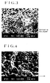
- Figs. 1 through 6 are electron microscope photographs illustrating textures of porous polypropylene hollow fiber membranes of the present invention.
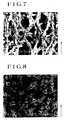
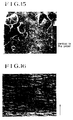
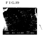
- Figs. 7 through 19 are electron microscope photographs illustrating textures of conventional porous hollow fiber membranes.
- Fig. 20 is a schematic cross section of an apparatus to be used for the method of production of a porous polypropylene hollow fiber membrane of the present invention.
- Fig. 21 is a semi-cross section illustrating a typical hollow fiber membrane type artificial lung as one embodiment of this invention.
- Fig. 22 is a cross section illustrating portions of the artificial lung relative to the hollow fiber membrane filling ratios.
- the porous polypropylene hollow fiber membrane of the present invention is a hollow fiber membrane of polypropylene substantially circular in cross section, possessing an inside diameter in the range of 150 to 300 ⁇ m, preferably 180 to 250 ⁇ m, a wall thickness in the range of 10 to 150 ⁇ m, desirably 20 to 100 ⁇ m, and more desirably 40 to 50 ⁇ m.
- the microstructure of this hollow fiber membrane of polypropylene is variable with the production conditions of the hollow fiber membrane. Generally, it acquires a microstructure as shown in the scanning electron microscope photographs of Figs.
- the solid phase is formed with particles of polypropylene closely fused and joined while partly exposed through the surface, namely, they are fused and then cooled and solidified to give rise to a continuous phase (Figs. 2 through 6).
- the solid phase is formed with a multiplicity of particles of polypropylene randomly gathered without any directionality in the circumferential direction (Fig.
- the solid phase in the interior of the membrane therefore, is believed to be formed with an aggregate of a multiplicity of lumps of polypropylene, which each consist of particles of polypropylene interconnected in the direction of axis of fiber. Further on the outer surface region similarly to the interior of the membrane, the solid phase is formed with an aggregate of a multiplicity of lumps of polypropylene, which each consist of particles of polypropylene interconnected in the direction of axis of fiber (Fig. 1).
- pores extending from the inner surface to the outer surface of the thick wall portion inclusive of the inner surface and the outer surface of the hollow fiber are interconnected not linearly but in a complicate reticular pattern to give rise to continuous pores of the form of a three-dimensional shape.
- the complexity of the arrangement of these continuous pores is evinced by the fact that the ratio of birefringent in the direction of axis of the porous polypropylene hollow fiber membrane of this invention is extremely low so as to fall in the range of 0.001 to 0.01 and the property of orientation of the polypropylene crystals is small.
- porous polypropylene hollow fiber membrane of the present invention constructed as described above When used in an artificial lung adapted to pass blood inside the hollow fiber, it neither inflicts any injury upon the blood cells nor induces any aggravation of pressure loss because the inner surface of the membrane consists of the continuous phase formed with particles of polypropylene closely fused and joined while partially exposed through the surface and the remaining part of pores and possesses the quality of smoothness.
- the porous polypropylene hollow fiber membrane when used in an artificial lung adapted to pass blood outside the hollow fiber, it neither inflicts any injury on the blood cells nor induces any aggravation of pressure loss because the outer surface of the membrane consists of the solid phase formed with an aggregate of a multiplicity of lumps of polypropylene each having particles of polypropylene arranged orderly in the direction of fiber and the remaining part of pores and possesses the quality of smoothness.
- the pores of the porous polypropylene hollow fiber membrane which serve as the routes for a gas when the porous polypropylene hollow fiber membrane is used in an artificial lung are continuous pores interconnected complexly and reticularly in a three-dimensional network.
- the extra-corporeal circulation of blood is effected either inside or outside the hollow fiber membrane, the blood plasma component of the blood cannot pass through such long complexly interlaced routes.
- the artificial lung shows substantially no sign of leakage of blood plasma or degradation of gas-exchange capacity after 30 hours' extra-corporeal circulation of blood, for example.
- the porosity is required to fall in the range of 10 to 60%, preferably 30 to 55%, the aperture ratio of the inner surface in the range of 10 to 30%, preferably 12 to 20%, and the oxygen gas flux in the range of 9.87 10 -4 to 1.48 10 -2 l/min.m 2 .Pa (100 to 1,500 liters/min.m 2 .atm), preferably 2.96 10 -3 to 7.9 10 -3 l/min.m 2 .Pa (300 to 800 liters/min.m 2 .atm). If the porosity is less than 10%, the membrane has the possibility of exhibiting an insufficient gas-exchange capacity.
- the membrane Conversely if the porosity exceeds 60%, the membrane has the possibility of leaking blood plasma. If the aperture ratio is less than 10%, the membrane has the possibility of exhibiting an insufficient gas-exchange capacity because of insufficient formation of continuous pores in the part of pores of the membrane. Conversely, if the aperture ratio exceeds 30%, the membrane has the possibility of suffering from leakage of blood plasma because of the lack of the complexity of continuous pores. If the oxygen gas flux deviates from the range of 9.87 10 -4 to 1.48 10 -2 l/min.m 2 .Pa (100 to 1,500 liters/min.m 2 .atm), the membrane has the possibility of failing to fulfil the function as a gas-exchange membrane.
- the sizes and distribution degrees of the particles of polypropylene and the continuous pores, i.e. the interstices between the adjacent particles of polypropylene, which make up the porous polypropylene hollow fiber membrane of the present invention can be controlled to their respectively desirable conditions by the production conditions of the membrane and the composition of raw materials used therefor.
- the particles of polypropylene are required to possess an average diameter in the range of 0.1 to 2.0 ⁇ m, preferably 0.2 to 1.5 ⁇ m and the pores opening in the inner surface to possess an average diameter in the range of 0.1 to 1.0 ⁇ m, preferably 0.3 to 0.6 ⁇ m.
- the porous polypropylene hollow fiber described above is produced, for example, as follows. As illustrated in Fig. 20, a mixture 11 of polypropylene, an organic filler, and a crystalline seed forming agent is fed through a hopper 12 into a kneader such as, for example, a uniaxial extruding machine 13, there to be fused, blended, and extruded. Then, the extruded mixture is forwarded to a spinning device 14, discharged through an annular spinning orifice (not shown) of a spinneret 15 into a gaseous atmosphere such as, for example, air.
- a kneader such as, for example, a uniaxial extruding machine 13
- a spinning device 14 discharged through an annular spinning orifice (not shown) of a spinneret 15 into a gaseous atmosphere such as, for example, air.
- a hollow thread 16 emanating from the spinneret 15 is introduced into a cooling tank 18 filled with a cooling and solidifying liquid 17, and cooled and solidified by contact with the cooling and solidifying liquid 17.
- the contact of the hollow thread 16 and the cooling and solidifying liquid 17 is desired to be effected by causing the aforementioned cooling and solidifying liquid 17 to flow down the interior of a cooling and solidifying liquid flow tube 19 disposed as directed downwardly through the bottom of the aforementioned cooling tank 18 as illustrated in Fig. 20 and allowing the aforementioned hollow thread 16 to fall down along the flow of the cooling and solidifying liquid and come into parallel contact therewith.
- the cooling and solidifying liquid 17 which has flowed down is received and stored in a solidifying tank 20.
- the hollow thread 16 is vertically introduced into the solidifying tank 20 and caused to change to course of travel by a deflection bar 21 so as to be solidified through ample contact therewith.
- the cooling and solidifying liquid 16 accumlating in the solidifying tank 20 is discharged via a circulation line 23 and circulated by a circulation pump 24 to the aforementioned cooling tank 18.
- the solidified hollow thread 16 is led to a shower conveyor type extruding machine 27 onto which an extractant 25 capable of dissolving the aforementioned organic filler and incapable of dissolving the polypropylene is dropped in the form of shower.
- the hollow thread 16 is brought into ample contact with the extractant and consequently deprived of the remaining organic filler while it is being advanced on a belt conveyor 26.
- the polypropylene to be used as one of the raw materials for this invention need not be limited to homopolymer of propylene. It may be a block polymer using propylene as the main component and additionally incorporating therein another monomer.
- the polypropylene is required to possess a melt index (M.I.) in the range of 5 to 70, preferably 10 to 40.
- M.I. melt index
- the homopolymer of propylene proves to be particularly desirable.
- that which has a high degree of crystallinity proves to be most desirable.
- the organic filler is required to be uniformly dispersible in the polypropylene which is in a molten state and to be easily soluble in an extractant to be used later.
- the filler which fulfils this requirement include liquid paraffin (number average molecular weight 100 to 2,000), ⁇ -olefin oligomers [such as, for example, ethylene oligomer (number average molecular weight 100 to 2,000), propylene oligomer (number average molecular weight 100 to 2,000), and ethylene oligomer (number average molecular weight 100 to 2,000)], paraffin wax (number average molecular weight 200 to 2,500), and various hydrocarbons.
- the liquid paraffin proves to be particularly desirable.
- the mixing ratio of the polypropylene and the aforementioned organic filler is such that the proportion of the organic filler to 100 parts by weight of the propylene is in the range of 35 to 170 parts by weight, preferably 80 to 150 parts by weight. If the proportion of the organic filler is less than 35 parts by weight, the produced hollow fiber membrane cannot manifest sufficient permeability to gas because part of the membrane is formed with a continuous phase of polypropylene. Conversely, if the proportion exceeds 170 parts by weight, the moldability of the mixture in the form of a hollow fiber is degraded because the viscosity of the mixture is unduly lowered.
- the mixture consisting of raw materials in a prescribed percentage composition is prepared (designed) by the premix method which comprises melting and blending the mixture, extruding the resultant blend, and pelletizing the extruded blend by the use of a biaxial type extruding machine, for example.
- the crystalline seed forming agent to be included in the raw materials for this invention is an organic heat-resistant substance possessing a melting point of not less than 150°C (preferably in the range of 200° to 250°C) and a gelling point of not less than the crystallization starting point of polyolefin.
- the crystalline seed forming agent of this description is used as one of the raw materials for the purpose of causing contraction of the particles of polypropylene thereby narrowing the interstices namely the continuous pores between the particles and heightening the pores density.
- the crystalline seed forming agent there can be cited 1,3,2,4-dibenzilydene sorbitol, 1,3,2,4-bis(p-methylbenzilydene) sorbitol, 1,3,2,4-bis(p-ethylbenzilydene) sorbitol, bis(4-t-butylphenyl) sodium phosphate, sodium benzoate, adipic acid, talc and kaoline.
- benzilyidene sorbitols especially 1,3,2,4-bis(p-ethylbenzilydene) sorbitol and 1,3,2,4-bis(p-methylbenzilydene) sorbitol prove to be particularly desirable because they are not significantly dissolved in the blood.
- the mixing ratio of the propylene and the aforementioned crystalline seed forming agent is such that the proportion of the crystalline seed forming agent to 100 parts by weight of the polypropylene is in the range of 0.1 to 5 parts by weight, preferably 0.2 to 1.0 part by weight.
- the mixture of raw materials prepared as described above is fused and blended in a uniaxial extruding machine, for example, at a temperature in the range of 160°C to 250°C, preferably 180° to 220°C, extruded through an annular orifice of a spinning device into gaseous atmosphere, when necessary, by the use of a gear pump enjoying high accuracy of measurement, to give rise to a hollow thread.
- a uniaxial extruding machine for example, at a temperature in the range of 160°C to 250°C, preferably 180° to 220°C, extruded through an annular orifice of a spinning device into gaseous atmosphere, when necessary, by the use of a gear pump enjoying high accuracy of measurement, to give rise to a hollow thread.
- an inactive gas such as, for example, nitrogen, carbon dioxide, helium, argon, or air may be delivered through spontaneous suction or, when necessary, forced introduction.
- the hollow thread discharged through the annular orifice is allowed to fall down into contact with the cooling and solidifying liquid held inside the cooling tank.
- the distance of this fall of the hollow thread is in the range of 5 to 1,000 mm, preferably 10 to 500 mm. If this distance is less than 5 mm, the hollow thread is caused to pulsate and is possibly crushed at the time the hollow thread enters the cooling and solidifying liquid.
- the hollow thread Inside this cooling tank, the hollow thread has not yet been thoroughly solidified and it is liable to be deformed by an external force because the central part of the membrane is formed with a gas.
- the aforementioned hollow thread can be forced to move and the deformation of the hollow thread by the external force (such as fluid pressure) can be precluded by allowing the aforementioned solidifying liquid 17 to flow down the interior of the cooling and solidifying tube 19 disposed as directed downwardly through the bottom of the cooling tank 18 as illustrated in Fig. 20 and allowing the hollow thread to fall parallelly to the flow of the liquid.
- the flow rate obtained by gravitational attraction suffices.
- the cooling temperature used in this case is in the range of 10° to 90°C, preferably 20° to 75°C.
- the cooling and solidifying speed is unduly high and the greater part of the thick wall part of the membrane assumes the form of a closely packed layer and the gas-exchange capacity of the membrane is proportionately lowered. If this temperature exceeds 90°C, the hollow thread is not sufficiently cooled and solidified and is possibly broken within the cooling and solidifying tank.
- the cooling and solidifying liquid for this invention a solution exhibiting no compatibility with the organic filler being used and possessing a specific heat capacity in the range of 8.37 10 2 to 2.93 10 3 J/kg.K (0.2 to 0.7 cal/g.K), preferably 1.26 10 3 to 2.51 10 3 J/kg.K (0.3 to 0.6 cal/g.K) is used.
- silicone oils such as dimethyl silicone oil and methylphenyl silicone oil possessing a kinetic viscosity in the range of 2 to 50 cSt, preferably 8 to 40 cSt, and polyethylene glycols possessing an average molecular weight in the range of 100 to 400, preferably 180 to 330.
- Such a liquid as exhibiting no compatibility with the organic filler being used and possessing a specific heat capacity in the range of 8.37 10 2 to 2.93 10 3 J/kg.K (0.2 to 0.7 cal/g.K) is used as the cooling and solidifying liquid for the following reason.
- liquid paraffin is used as the organic filler and a halogenated hydrocarbon is used as the cooling and solidifying liquid capable of dissolving the organic filler mentioned ablove
- the organic filler will be dissolved and extracted out and will pass from the inner to the outer side of the hollow thread while the phase separation of the polypropylene and the organic filler is proceeding in the cooling and solidifying liquid, the proportion of the organic filler near the inner surface of the hollow thread is lowered after the hollow thread has been thoroughly cooled and solidified, and the ratio of openings in the inner surface is unduly lowered and the gas-exchange capacity of the membrane is suffered to fall after the organic filler has been thoroughly dissolved and extracted out.
- the organic filler (liquid paraffin) in the hollow thread is allowed to give rise to pores in a prescribed density without being significantly migrated within the hollow thread and the specific heat is not unduly large and, as the result, the polypropylene is crystallized at a proper cooling speed and enabled to acquire a stable form finally.
- the cooling and solidifying liquid When an inactive liquid which is incompatible with the organic filler and possesses a large specific heat capacity is used as the cooling and solidifying liquid, namely when liquid paraffin is used as the organic filler and water having a large specific heat capacity of about 4.18 10 3 J/kg.K (1.0 cal/g.K) is used as the cooling and solidifying agent, there is the possibility that the polypropylene will be quickly cooled and the outer surface will assume a state of low crystallinity because the cooling effect of water is high. The possible consequence is that the polypropylene will fail to form minute particles and the produced hollow fiber membrane will contain unduly small pores in the outer surface thereof and exhibit a small gas-exchange capacity. If the cooling and solidifying liquid to be used possesses a small specific heat capacity, there is the possibility that no sufficient cooling effect will be obtained and the extruded mixture will not be converted into a hollow thread as desired.
- the outer surface of the hollow fiber membrane similarly to the interior thereof, is formed with an aggregate of a multiplicity of lumps of polypropylene each having minute particles of polypropylene interconnected in the direction of axis of fiber and is allowed to assume a smooth surface condition because the polypropylene is cooled at a proper speed and the polypropylene is crystallized smoothly while keeping a proper polypropylene composition ratio even in the outer surface, while the organic filler is not locally distributed on the outer surface of the hollow fiber.
- the hollow thread which has been cooled and solidified in the cooling and solidifying tank is forwarded to an extracting machine, for example, as passed around a deflection bar to dissolve and extract the organic filler.
- the means for dissolving and extracting the organic filler need not be limited to the shower method which resides in causing the extractant to fall in the form of shower onto the hollow thread being forwarded on the belt conveyor as shown in Fig. 20.
- the extraction tank method or the rewinding method which, at the time that the hollow thread once wound up in a roll is rewound on a skein frame, immerses the skein in the extractant on the sole condition that the treatment should bring the hollow thread into contact with the extractant.
- two or more such methods may be used in combination.
- the extractant there can be used any of the liquids which are incapable of dissolving the propylene which forms the backbone of the hollow fiber membrane and capable of dissolving and extracting the organic filler.
- the liquid so usable include alcohols such as methanol, ethanol, propanols, butanols, pentanols, hexanols, octanols, and lauryl alcohol and halogenated hydrocarbons such as 1,1,2-trichloro-1,2,2-trifluoroethane, trichlorofluoromethane, dichlorofluoromethane, and 1,1,2,2-tetrachloro-1,2-difluoroethane.
- halogenated hydrocarbons prove to be desirable from the standpoint of extraction capacity and chloro-fluorinated hydrocarbons prove to be especially desirable from the standpoint of safety on the human system.
- the hollow fiber membrane which is obtained as described above, when necessary, is further subjected to a heat treatment.
- the heat treatment is carried out in a gaseous atmosphere such as air, nitrogen or carbon dioxide at a temperature in the range of 50 to 160°C, preferably 70 to 120°C, for a period in the range of 5 seconds to 120 minutes,preferably 10 seconds to 60 minutes.
- a gaseous atmosphere such as air, nitrogen or carbon dioxide
- the hollow fiber membrane is structurally and dimentionally stabilized.
- the hollow fiber membrane may be stretched prior to or during the heat treatment.
- porous polypropylene hollow fiber membrane which is obtained as described above is used most suitably in a hollow fiber membrane type artificial lung.
- the hollow fiber membrane which is obtained by the conventional stretching method possesses gas permeability more than is necessary for an artificial lung.
- the oxygen addition ability encounters a large boundary membrane resistance on the blood side and the resistance of the hollow fiber membrane has no rate-determining effect and, in the meantime, the ability to remove carbon dioxide gas depends on the resistance of the hollow fiber membrane and the permeability to gas is excessive.
- the gas-exchange capacity also depends on the resistance of the hollow membrane but the permeability is excessive.
- the hollow fiber membrane of the present invention in its simple form possesses gas permeability lower than that of the conventional stretching method. It, however, acquires quality enough for the membrane to be used efficiently in an artificial lung. Moreover, since it is produced by the extraction method, it produces no pinhole and induces no leakage of blood and, therefore, is capable of preventing the gas-exchange capacity from falling.
- the hollow fiber membrane which is obtained by using, as the cooling and solidifying liquid, a liquid identical or similar to the organic filler, particles of polypropylene are interconnected in the form of a network and consequently caused to assume a heavily rugged surface.
- the outer surface of the membrane similarly to the interior thereof, is formed with an aggregate of a multiplicity of lumps of polypropylene each having particles of polypropylene interconnected in the direction of axis of fiber and, therefore, is allowed to assume a smooth surface condition.
- the a multiplicity of such hollow fibers are assembled to form an artificial lung, the aforementioned drawbacks are not encountered.
- the membranes neither inflict any injury on the blood cells nor aggravate pressure loss.
- FIG. 21 illustrates the condition of assembly of a hollow fiber membrane type artificial lung as one version of the hollow fiber membrane type artificial lung of the present invention.
- a hollow fiber membrane type artificial lung 51 is provided with a housing 56.
- This housing 56 comprises a cylindrical main body 57 and annular fitting covers 58, 59 fastened with a male screw to the opposite ends of the tubular main body.
- a large number falling in the range of 10,000 to 65,000 of hollow fiber membranes 1 obtained as described above are disposed parallelly along the longitudinal direction of the housing 56 as individually separated throughout the entire interior.
- the opposite ends of these hollow fiber membranes 1 are water-tightly supported with diaphragms 60, 61 inside the fitting covers 58, 59 in such a manner that the openings thereof will not be blocked up.
- the diaphragms 60, 61 mentioned above define an oxygen-containing gas chamber 62 as a first substance transfer fluid flow space in conjunction with the outer surfaces of the hollow fiber membranes 1 and the inner surface of the housing 56 and will block up the oxygen-containing gas chamber 62. They also function to isolate the oxygen-containing gas chamber 62 from blood flow spaces (not shown) which are formed inside the aforementioned hollow fiber membranes 1 for a second substance transfer fluid.
- the fitting cover 58 is provided with an inlet 63 for supply of an oxygen-containing gas as the first substance transfer fluid.
- the other fitting cover 59 is provided with an outlet 64 for discharge of the oxygen-containing gas.
- the tubular main body 57 of the aforementioned housing 56 is desired to be provided on the inner surface thereof halfway along the direction of axis with a projected constricting part 65.
- This constricting part 65 is integrally formed with the tubular main body 57 on the inner surface and adapted to squeeze the overall outer periphery of a hollow fiber bundle 66 consisting of the multiplicity of hollow fiber membranes 1 inserted inside the tubular main body 57.
- the aforementioned tubular fiber bundle 66 is constricted at the center in the direction of axis to form a contricted part 67 as illustrated in Fig. 21.
- the packing ratio of the hollow fiber membranes 1, therefore, varies along the direction of axis and reaches the maximum at the center.
- the packing ratios of varying parts of the hollow fiber bundle 66 are desired to be as follows.
- the packing ratio A in the constricted part 67 at the center is approximately in the range of 60 to 80%
- the packing ratio C at the opposite ends of the hollow fiber bundle 66 namely on the outer surfaces of the diaphragms 60, 61 in the range of 20 to 40% as illustrated in Fig. 22.
- the diaphragms 60, 61 fulfil an important function of isolating the interiors from the exteriors of the hollow fiber membranes 1.
- these diaphragms 60, 61 are formed by centrifugally casting a macromolecular potting material of high polarity such as, for example, polyurethane, silicone, or epoxy resin in the inner wall surfaces at the opposite ends of the housing 56 and allowing the cast macromolecular material to harden.
- a multiplicity of hollow fiber membranes 1 of a length greater than that of the housing 56 are prepared and, with the openings thereof at the opposite ends blocked up with highly viscous resin, parallelly disposed inside the tubular main body 57 of the housing 56.
- the opposite ends of the hollow fiber membranes 1 are completely concealed with pattern covers of a diameter larger than that of the fitting covers 58, 59 and the housing 56 is set rotating about the axis thereof and, at the same time, the macromolecular potting material is cast into the housing 56 through the opposite ends thereof.
- the aforementioned pattern covers are removed and the outer surface parts of the resin are cut off with a sharp blade to expose the open ends of the hollow fiber membranes 1 from the surfaces. In this manner, the diaphragms 60, 61 are formed.
- the outer surfaces of the aforementioned diaphragms 60, 61 are respectively covered with flow path forming members 68, 69 each possessed of an annularly raised part.
- These flow path forming members 68, 69 severally consist of liquid distribution members 70, 71 and thread rings 72, 73.
- An inlet chamber 76 and an outlet chamber 77 for the blood as the second substance transfer fluid are formed by causing annular ridges 74, 75 disposed near the peripheral parts of the liquid distribution members 70, 71 to be pressed by the edge surfaces on the diaphragms 60, 61 mentioned above and helically fastening the thread rings 72, 73 to the fitting covers 58,59.
- an inlet 78 and an outlet 79 for the blood as the second substance transfer fluid are formed in the flow path forming members 68, 69.
- Gaps are formed around the diaphragms 60, 61 as defined by the diaphragms 60, 61 and the flow path forming members 68, 69. These gaps are sealed as held in contact with the diaphragms 60, 61 by injecting a filler 84 or 85 through at least either of the two holes 80, 82, and 81, 83 communicating with the gaps. The sealing may be otherwise effected through the medium of an O-ring (not shown).
- the hollow fiber membrane type artificial lung of the present embodiment is of a type adapted to use an oxygen-containing gas like air as the first substance transfer fluid and blood as the second substance transfer fluid, namely to feed the oxygen-containing gas outside the hollow fiber membranes and circulate blood inside the hollow fiber membranes to effect desired exchange of gases.
- the hollow fiber membrane type artificial lung of this invention may be of another type adapted to circulate blood outside the hollow fiber membranes and feed the oxygen-containing gas inside the hollow fiber membranes to effect desired exchange of gases.
- the hollow fiber membrane type artificial lung has entirely the same construction as that of the present embodiment and is operated by using the blood as the first substance transfer fluid and the oxygen-containing gas as the second substance transfer fluid.
- the hollow thread 16 was brought into contact with a varying cooling and solidifying liquid indicated in Table 1 held in a cooling tank 18 and then cooled by parallel-flow contact with the cooling and solidifying liquid 17 spontaneously flowing down the interior of the cooling and solidifying liquid flow tube 19.
- the temperature of the cooling and solidifying liquid was varied as shown in Table 1.
- the aforementioned hollow thread 16 was led into the cooling and solidifying liquid inside a solidification tank 20, caused to change the course of its travel by a deflection bar 21, then led to a drive roll 22 operated at a varying winding speed indicated in Table 1, continuously treated on a shower conveyor type extracting machine 27 with Freon 113 (1,1,2-trichloro-1,2,2-trifluoroethane) to effect thorough removal of the aforementioned liquid paraffin by extraction, passed around a drive roll 22, passed through a heat-treating device 30 under varying temperature and time conditions indicated in Table 1, and taken up on a bobbin 32 by a winder 31.
- hollow fiber thus taken up on the bobbin 32 was rewound on a skein by a rewinding device to obtain a hollow fiber bundle about 30 cm in length.
- the hollow fiber membrane thus obtained was examined with respect to shape (wall thickness), porosity, opening ratio in the inner surface, gas flux, ability to add oxygen gas, ability to remove carbon dioxide gas, leakage of blood plasma, and speed of blood plasma permeation. The results are shown in Tables 2 and 3.
- Fig. 1 is a photomicrograph of the outer surface (x 10,000) of the hollow fiber membrane of Example 1
- Fig. 2 of the inner surface (x 10,000) of the hollow fiber membrane of Example 1
- Fig. 3 of the cross section (x 10,000) of the hollow fiber membrane of Example 1
- Fig. 4 of the longitudinal cross section (x 10,000) of the hollow fiber membrane of Example 1
- Fig. 5 of the outer surface (x 10,000) of the hollow fiber membrane of Example 2
- Example 1 The hollow fiber membranes of Example 1 and Control 1 were tested for ratio of birefringent as an index of crystal orientation. The results are shown in Table 4.
- a commercially available artificial lung-grade polypropylene hollow fiber membrane produced by the stretching method was tested for shape (inside diameter/wall thickness), porosity, opening ratio in inner surface, gas flux, ability to add oxygen gas, ability to remove carbon dioxide gas, leakage of blood plasma, and blood plasma permeation speed in the same manner as in Examples 1 and 2 and Controls 1 through 3.
- the results are shown in Tables 2 and 3.
- the microstructrue of the hollow fiber membrane was observed under a scanning electron microscope (made by JEOL and marketed under product code of "JSM-840").
- Fig. 16 is a photomicrograph of the outer surface (x 10,000) of this hollow fiber membrane, Fig. 17 of the inner surface (x 10,000) thereof, Fig. 18 of the cross section (x 10,000) thereof, and Fig. 19 of the longitudinal cross section (x 10,000) thereof, taken under the electron micrograph.
- the direction of axis fibers in the hollow fiber membrane is shown on the right.
- the hollow fiber membrane was tested for ratio of birefringent as an index of crystal orientation. The results are shown in Table 4.
- a module of the type adapted to pass blood outside the hollow fiber membrane was assembled using the hollow fiber membrane and tested for hemolysis of blood and pressure loss of blood in the same manner as in Example 1 and Control 1.
- the hollow fibers randomly selected from a given lot were cut laterally to obtain rings about 0.5 mm in length with a sharp razor blade.
- the numerical values thus obtained with respect to the ten hollow fibers were averaged to be reported.
- the inner surface of a given hollow fiber was photographed under a scanning electron microscope (produced by JEOL and marketed under product code of "JSM-840") at 3,000 magnifications. The photograph was enlarged on a quarter printing paper (about 7,500 magnifications on the printing paper). On the product print, four linear lines were randomly drawn each in the direction of axis of fibers and the direction perpendicular thereto. The ratio of the sum of lengths of pores intersected by the linear lines to the total length of the linear lines was reported as the Aperture ratio of the inner surface.
- a miniature module 14 cm in available length and 0.025 m 2 in membrane surface was produced using given hollow fibers. With one end of the module tightly closed, 1 atmosphere of oxygen pressure was applied on the interior of hollow fibers. After the system assumed the steady state, the flow volume of oxygen gas was read from the flow meter (produced by Kusano Rikagakukiki Seisakusho and marketed under trademark designation of "Floatmeter”) and reported as oxygen gas flux.
- An artificial lung module 130 mm in available length and 1.6 m 2 of membrane surface was produced using given hollow fibers.
- bovine blood standard venous blood
- pure oxygen was passed at a flow volume of 1.6 liters/min. outside the hollow fibers.
- the bovine blood was tested for pH, carbon dioxide partial pressure and oxygen gas partial pressure at the inlet and outlet of the artificial lung with an instrument (produced by Radiometer Corp. and marketed under product cope of "BGA3") and the differences of partial pressured at the inlet and outlet of the artificial lung.
- Table 7 Further details on the use of the artificial lung module are shown in Table 7.
- the attributes of the standard arterial blood are shown in Table 8.
- Table 7 Membrane surface (m 2 ) Inside/outisde diameter ( ⁇ m) Number of holllow fibers Available length/total length (cm) Packing ratio* (%) Part A Part B Part C Examples 1 and 2 and Control 1 1.6 200/290 19700 13/16 60 50 43 Control 4 1.6 200/245 19700 13/16 64 42 33 *
- Packing ratio means the ratio of the cross-sectional area (inclusive of empty spaces) of hollow fiber membrane to the cross-sectional area inside the cylinder proper in a varying part indicated in Fig. 22.
- An artificial lung module similar to that used for the determination of the ability to add oxygen gas and the ability to remove carbon dioxide gas was prepared, inserted in a partial V-A bypass circuit established by the jugular vein-jugular artery cannulation in a mongrel dog (weighing about 20 kg), and used for 30 minutes extracorporeal circulation of blood to measure the amount of blood plasma leaking from within the hollow fibers. Where there was no discernible leakage of blood plasma, drops of steam condensate formed outside the hollow fibers were tested for protein reaction to ensure detection of even slight leakage of blood plasma.
- a miniature module similar to that used for the determination of gas flux was prepared, successiveively immersed in aqueous 100%, 80%, 50%, and 0% ethanol solution, for 2 hours each.
- the blood plasma obtained by centrifuging bovine blood was circulated through this miniature module with the intermembranous pressure (TMP) adjusted to 22.1 10 3 (0.225 kg/cm 2 ).
- TMP intermembranous pressure
- the amount of blood plasma which had permeated the membrane was measured with a measuring cylinder.
- An artificial lung module of the mode adapted to circulated blood outside hollow fiber membranes and satisfying the specification shown in Table 9 was prepared using given hollow fiber membranes and used for 6 hours' circulation of fresh heparin-added bovine blood to determine the amount of free hemoglobin in the blood by the TMB method.
- the condition of hemolysis in the blood was rated by comparing the amount of free hemoglobin mentioned with that obtained by circulating the same bovine blood through a circuit incorporating no artificial lung.
- the pressure loss was measured before and after the artificial lung.
- Table 9 Number of hollow fiber membranes 48,160 Available length 80 mm Overall length 135 mm Packing ratio in the central part (Part A) 48%
- this invention concerns a porous polypropylene hollow fiber membrane wherein the solid phase in the inner surface region thereof is formed with particles of polypropylene closely fused and joined to give rise to a continuous phase while partially exposed through the surface thereof, the solid phase in the interior and the outer surface region thereof is formed with particles of polypropylene interconnected in the direction of axis of fiber to give rise to a multiplicity of lumps of polypropylene, and the interstice between these solid phases has continuous pores interconnected in the form of a three-dimensional network.
- this porous polypropylene hollow fiber membrane When this porous polypropylene hollow fiber membrane is used in an artificial lung, therefore, it induces no leakage of blood plasma and yet retains a high gas-exchange capacity even during a protracted service and, without reference to the choice of the type of the artificial lung on account of the mode of circulation of blood either inside or outside the hollow fiber membrane, neither imparts any injury to blood cells nor aggravates pressure loss of the blood. Since the porous polypropylene hollow fiber membrane possesses a smooth outer surface, it proves to be highly advantageous in respect that it is free from various drawbacks otherwise incurred during the assembly of an artificial lung such as cohesion of adjacent hollow fiber membranes or impairment of the work of potting due to adhesive agent.
- the ratio of birefringent in the direction of axis thereof is in the range of 0.001 to 0.01, the porosity in the range of 10 to 60%, the opening ratio in the inner surface in the range of 10 to 30%, the oxygen gas flux in the range of 9.87 10 -4 to 1.48 10 -2 l/min.m 2 .Pa (100 to 1,500 liters/min.m 2 .atm), the inside diameter in the range of 150 to 300 ⁇ m, the wall thickness in the range of 10 to 150 ⁇ m, the average diameter of polypropylene particles in the range of 0.1 to 2.0 ⁇ m, and the average pore diameter in the inner surface in the range of 0.1 to 1.0 ⁇ m.
- This invention further concerns a method for the production of a porous polypropylene hollow fiber membrane, which is characterized by mixing polypropylene, an organic filler uniformly dispersible in the polypropylene in a molten state and easily soluble in an extractant to be used later, and a crystalline seed forming agent, discharging the resultant mixture in a molten state through annular spinning orifices, cooling and solidifying the resultant hollow threads by contact with a cooling and solidifying liquid having no compatibility with the aforementioned organic filler and possessing a specific heat capacity in the range of 8.37 10 2 to 2.93 10 3 J/kg.K (0.2 to 0.7 cal/g.K) and then bringing the cooled and solidified hollow threads into contact with an extractant capable of dissolving polypropylene thereby removing the organic filler therefrom by extraction.
- the phase separation of the polypropylene and the organic filler in the spinning dope can be effected at a proper cooling speed without inducing any local presence of the organic filler in the outer surface part and, as the result, numerous micropores can be produced in the interstices of properly crystallized and grown particles of polypropylene and, moreover, the outer surface part as well as the thick wall part of the hollow fiber can form a solid phase having particles of polypropylene orderly arranged in the direction of axis of fiber and assume a smooth surface.
- a hollow fiber membrane which exhibits the aforementioned outstanding properties stably and uniformly.
- the porous polypropylene hollow fiber membrane possessing still better properties can be obtained when a silicone oil or polyethylene glycol, preferably a silicone oil possessing a viscosity in the range of 2 to 50 cSt or a polyethylene glycol possessing an average molecular weight in the range of 100 to 400, is used as the cooling and solidifying liquid, liquid paraffin is used as the organic filler, the proportion of the organic filler to 100 parts by weight of polypropylene is in the range of 35 to 150 parts by weight, an organic heat-resistance substance possessing a melting point of not less than 150°C and a gelling point of not less than the crystallization starting point of polypropylene is used as the crystalline seed forming agent, and the proportion of the crystalline seed forming agent to 100 parts by weight of polypropylene is in the range of 0.1 to 5 parts by weight.
- a silicone oil or polyethylene glycol preferably a silicone oil possessing a viscosity in the range of 2 to 50 cSt or a
- This invention also concerns an artificial lung provided with a hollow fiber membrane as a gas-exchange membrane, characterized by the fact that the hollow fiber membrane is a porous polypropylene hollow fiber membrane wherein the solid phase in the inner surface region thereof is formed with particles of polypropylene closely fused and joined to give rise to a continuous phase while partially exposed through the surface thereof, the solid phase in the interior and the outer surface region thereof is formed with particles of polypropylene interconnected in the direction of axis of fiber to give rise to a multiplicity of lumps of polypropylene, and the interstice between these solid phases has continuous pores interconnected in the form of a three-dimensional network.
- the artificial lung of either the type adapted to circulate the blood inside the hollow fiber membrane and blow the oxygen-containing gas outside the hollow fiber membrane or the type adapted to circulate the blood outside the hollow fiber membrane and blow the oxygen-containing gas inside the hollow fiber membrane, therefore, the ability of the membrane to add oxygen and the ability to remove carbon dioxide gas are not degraded even during a protracted service in the extra-corporeal circulation of blood, no leakage of blood or blood plasma is induced, and neither infliction of injury upon blood cells nor aggravation of pressure loss is entailed. Thus, the artificial lung deserves to be esteemed highly. Typically in 30 hours' extra-corporeal circulation of blood, the artificial lung of the present invention incurs neither leakage of blood plasma nor degradation of gas-exchange capacity.
- the properties of the artificial lung are manifested more to advantage when the ratio of birefringent in the direction of axis of fiber is in the range of 0.001 to 0.01, the porosity in the range of 10 to 60%, the opening ratio in the inner surface in the range of 10 to 30% , the oxygen gas flux in the range of 9.87 10 -4 to 1.48 10 -2 l/min.m 2 .Pa (100 to 1,500 liters/min.m 2 .atm.), and inside diameter in the range of 150 to 300 ⁇ m, the wall thickness in the range of 10 to 100 ⁇ m, the average diameter of polypropylene particles in the range of 0.1 to 2.0 ⁇ m, and the average pore diameter in the inner surface in the range of 0.1 to 1.0 ⁇ m.
Landscapes
- Chemical & Material Sciences (AREA)
- Chemical Kinetics & Catalysis (AREA)
- Engineering & Computer Science (AREA)
- Textile Engineering (AREA)
- General Chemical & Material Sciences (AREA)
- Manufacturing & Machinery (AREA)
- Mechanical Engineering (AREA)
- External Artificial Organs (AREA)
- Separation Using Semi-Permeable Membranes (AREA)
- Artificial Filaments (AREA)
Abstract
Description
- This invention relates to a porous polypropylene membrane and a method for the production thereof.
- Further, this invention relates to a porous polypropylene hollow fiber membrane, a method for the production thereof, and an artificial lung using the hollow fiber membrane. More particularly, this invention relates to a porous polypropylene hollow fiber membrane possessing a high gas-exchange capacity, a method for the production thereof, and an artificial lung using the hollow fiber membrane. Still more particularly, this invention relates to a porous polypropylene hollow fiber membrane which, while being used in an artificial lung of the type passing blood inside or the type passing blood outside the hollow fiber membrane, exhibits a high gas-exchange capacity without inflicting damage upon blood components, inducing an increase in the pressure loss, or suffering from leakage of blood plasma during a protracted service, a method for the production thereof, and an artificial lung using the hollow fiber membrane.
- Generally in the cardiac operation, an artificial lung of hollow fiber membrane is used as inserted in the extra-corporeal circulatory path for the purpose of leading a patient's blood out of his body, adding oxygen to the blood, and removing carbon dioxide gas from the blood. The hollow fiber membranes available in the artificial lungs of this nature come in the two types, namely the homogeneous membrane and the porous membrane. The homogeneous membrane effects passage of a gas by allowing the molecules of the gas to be dissolved and dispersed in the membrane. A typical example of the homogeneous membrane is silicone rubber, which has been commercialized as MERA SILOX (Senko Ika Kogyo K.K.),for instance. Because of the restriction imposed by the gas permeability, silicone rubber is the only practicable homogeneous membrane known to the art. The silicone rubber membrane, by reason of strength, is not allowed to have a wall thickness less than 100 µm. It, therefore, has limited gas permeability and exhibits particularly poor permeability to carbon dioxide gas. Worse still, the silicone rubber has a disadvantage that it is expensive and deficient in workability.
- In contrast, the porous membrane is such that the micropores contained in the membrane are notably large as compared with the molecules of a gas given to be passed and, therefore, the gas passes the micropores in the form of volume flow. Various artificial lungs using microporous polypropylene membranes and other similar porous membranes have been proposed. It has been proposed, for example, to manufacture porous polypropylene hollow fibers by melt spinning polypropylene with a nozzle for the production of hollow fibers at a spinning temperature in the range of 210° to 270°C at a draft ratio in the range of 180 to 600, then subjecting the spun fibers to a first heat treatment at a temperature of not more than 155°C, stretching the hot spun fibers to an extent in the range of 30 to 200% at a temperature below 110°C, and subjecting the stretched fibers to a second heat treatment at a temperature exceeding the temperature of the first heat treatment and not exceeding 155°C (JP-A-56 052 123). In the porous hollow fibers obtained as described above, since the micropores are physically formed by stretching polypropylene hollow fibers, they are linear micropores substantially horizontal to the direction of the membrane thickness. Further, these micropores are formed by producing cracks in the axial direction of hollow fibers in conformity with the degree of stretching, they have a cross section of the shape of a slit. Moreover, the micropores continuously run substantially linearly through the membrane and account for a high porosity. The porous hollow fibers described above, therefore, have a disadvantage that they exhibit high permeability to steam and, when used for extracorporeal circulation of blood for a long time, suffers leakage of blood plasma.
- As a porous membrane incapable of incurring leakage of blood plasma, a porous polyolefin hollow fiber has been proposed which is produced by mixing a polyolefin, an organic filler uniformly dispersible in the polyolefin while the polyolefin is in a molten state and readily soluble in an extractant to be used later, and a crystalline core forming agent, discharging the resultant mixture in a molten state through annular spinning orifices and, at the same time, introducing inactive gas into the interiors of the hollow threads of the mixture, cooling and solidifying the hollow threads by contact with a cooling and solidifying liquid incapable of dissolving the aforementioned polyolefin, and then bringing the cooled and solidified hollow threads into contact with the aforementioned extractant thereby removing the aforementioned organic filler by extraction from the hollow threads (EP-A-0 180 052 or JP-A-61 090 705). The polypropylene hollow fiber membrane, one version of the aforementioned hollow fiber membrane which is obtained by using, as a cooling and solidifying liquid, a cooling and solidifying liquid capable of dissolving the organic filler to be used as desirable for the process, however, has a small pore density per unit area and possibly offers an insufficient gas-exchange capacity for use in an artificial lung, though it has no possibility of incurring leakage of blood plasma because the pores are small and complicate in shape. There is another possibility that the low molecular component of the polyolefin will mingle into the cooling and solidifying liquid capable of dissolving the organic filler, eventually adhere to the inner wall of the cooling bath, and cause the shape of the hollow fibers to vary with elapse of time.
- As an amendment of such drawbacks as mentioned above, there has been proposed a porous polyolefin hollow fiber membrane produced by a process which comprises mixing polypropylene, an organic filler uniformly dispersible in the polypropylene while the polypropylene is in a molten state and readily soluble in an extractant to be used later,and a crystalline core forming agent, discharging the resultant mixture in a molten state through annular spinning orifices thereby forming hollow threads, cooling and solidifying the hollow threads by contact with a liquid of the aforementioned organic filler or a compound similar threreto, and then bringing the cooled and solidified hollow threads into contact with the extractant incapable of dissolving the polypropylene thereby removing the aforementioned organic filler from the hollow threads by extraction (JP-A-62 106 770). The hollow fiber membrane which is obtained by this method is free from the drawbacks enumerated above. During the course of cooling, however, the organic filler or the cooling and solidifying liquid is locally deposited on the outermost surfaces of the hollow fibers which have not yet been thoroughly cooled and solidified, to lower the ratio of distribution of the polypropylene composition on the outermost surfaces and consequently enlarge the pores in the outer surfaces of the hollow fibers and cause the polypropylene to continue in the form of a heavily rugged network. When the hollow fibers of this nature are used in an artificial lung of the type adapted to pass blood inside the hollow fibers and blow an oxygen-containing gas outside the hollow fibers to effect addition of oxygen to the blood and removal of carbon dioxide gas from the blood, no problem is raised. Conversely when the hollow fibers are used in an artificial lung of the type adapted to flow blood outside the hollow fibers and blows an oxygen-containing gas inside the hollow fibers, they entail a disadvantage that the outer surface of the hollow fibers, owing to their quality described above, inflict an injury on the blood cells and aggravate the pressure loss. Further, the artificial lung using such a hollow fiber membrane as described above, without reference to the choice between the two types of artificial lung, has a disadvantage that during the course of assembly of the artificial lung, the individual hollow fibers conglomerate to impair the workability thereof and jeopardize the effect of potting.
- Heretofore, various permeable membranes have been adopted for the purpose of separating blood into blood cells and blood plasma. These permeable membranes are used for blood plasma purification aimed at removal of abnormal proteins, antigens, antibodies, and immune complexes in such diseases due to abnormal immunity as systemic lupus erythematosus, rheumatoid arthritis, glomerular nephritis, and myasthenia gravis, for manufacture of blood plasma preparations for component transfusion, and for pretreatment of artificial kidneys, for example. As examples of the permeable membranes heretofore used for the blood plasma separation mentioned above, there can be cited a cellulose acetate membrane (JP-A-54 015 476) and a polyvinyl alcohol membrane, a polyester membrane, a polycarbonate membrane, a polymethyl methacrylate membrane, and a polyethylene membrane (JP-A-57 084 702). These permeable membranes are deficient in mechanical strength, porosity, and plasma separating ability. When these permeable membranes are used in the blood plasma separation, owing to the clogging of the micropores therein, the erythrocytes are injured and the components of complement in the blood plasma are activated and the separated blood plasma is seriously injured as the result.
- A permeable membrane has been proposed which is produced by mixing a polymer such as a crystalline polyolefin or polyamide which is sparingly soluble in a solvent and is stretchable and a compound partially compatible with the polymer and readily soluble in the solvent, molding the resultant mixture in the form of film, sheet, or a hollow article, treating the shaped article with the solvent, drying the treated shaped article, and then uniaxially or biaxially stretching the dried shaped article to an extent fallng in the range of 50 to 15,000% (JP-A-57 020 970). Since this membrane has been stretched for the purpose of increasing pore diameter, it is susceptible of thermal shrinkage so much that, when the permeable membrane is used in a medical device, it will not be able to be safely sterilized in an autoclave. Moreover since the micropores are formed by stretching in the permeable membrane, they are linear micropores substantially parallel to the direction of thickness of the membrane. Since the micropores have a substantially uniform shape in the opposite surfaces and in the interior of the wall of the membrane, they are inevitably clogged with proteins and blood cells when the permeable membrane is used in the blood plasma separation.
- A hollow fiber membrane has been proposed, which is produced by mixing polypropylene, an organic filler capable of uniformly dispersing in the polypropylene in a fused state and easily dissolving in an extractant being used, and a crystal seed forming agent, causing the resulting mixture in a molten state to be discharged in the shape of a hollow fiber through an annular spinning nozzle, forwarding said hollow fiber into contact with a liquid made of said organic filler or a compound similar thereto thereby cooling and solidifying said hollow fiber, and forwarding the cooled and solidified hollow fiber into contact with an extractant incapable of dissolving polypropylene thereby depriving said hollow fiber of said organic filler (EP-A-0 209 465, belonging to the state of the art according to Article 54(3) EPC).
- An object of this invention, therefore, is to provide an improved porous polypropylene membrane and a method for the production thereof.
- Another object of this invention, is to provide an improved porous polypropylene hollow fiber membrane, a method for the production thereof, and an artificial lung using the hollow fiber membrane. A further object of this invention is to provide a porous polypropylene hollow fiber membrane possessing a high gas-exchange capacity, a method for the production thereof, and an artificial lung using the hollow fiber membrane. Still another object of this invention is to provide a porous polypropylene hollow fiber membrane which, while being used in an artificial lung of either of the type passing blood inside or the type passing blood outside, induces no leakage of blood plasma and retains a high gas-exchange capacity intact through a protracted service without impairing blood cells or aggravating pressure loss and which, therefore, is useful for an artificial lung, a method for the production thereof, and an artificial lung using the hollow fiber membrane. Yet another object of this invention is to provide a porous polypropylene hollow fiber membrane which possesses a smooth outer surface and defies conglomeration of individual hollow fibers thereof during the course of assembly of an artificial lung, a method for the production thereof, and an artificial lung using the hollow fiber membrane.
- The various objects described above are accomplished by a porous polypropylene hollow fiber membrane wherein the solid phase in the inner surface region thereof is formed with particles of polypropylene closely fused and joined to give rise to a continuous phase while partially exposed through the surface thereof, the solid phase in the interior and the outer surface region thereof is formed with particles of polypropylene interconnected in the direction of axis of fiber to give rise to a multiplicity of lumps of polypropylene, and the interstice between these solid phases has continuous pores interconnected in the form of a three-dimensional network.
- This invention also discloses a porous polypropylene hollow fiber membrane, wherein the index of birefringent thereof in the direction of axis is in the range of 0.001 to 0.01. This invention further discloses a porous polypropylene hollow fiber membrane, wherein the porosity thereof is in the range of 10 to 60% and the aperture ratio of the inner surface region thereof is in the range of 10 to 30% and the oxygen gas flux is in the range of 9.87 10-4 to 1.48 10-2 l/min.m2.Pa (100 to 1,500 liters/min.m2.atm). This invention further discloses a porous polypropylene hollow fiber membrane, wherein the inside diameter is in the range of 150 to 300µm and the wall thickness in the range of 10 to 150µm. This invention also discloses a porous polypropylene hollow fiber membrane, wherein the average diameter of the particles of polypropylene is in the range of 0.1 to 2.0µm and the average diameter of the pores in the inner surface region is in the range of 0.1 to 1.0 µm. This invention further discloses a porous polypropylene hollow fiber membrane, wherein the membrane used in an artificial lung is substantially free from leakage of blood plasma or degradation of gas-exchange capacity within 30 hours of service. Further this invention discloses a porous polypropylene hollow fiber membrane, wherein the membrane used in an artificial lung sparingly inflicts injury on blood cells.
- The objects described above are accomplished by a method for the production of a porous polypropylene hollow fiber membrane, which is characterized by mixing polypropylene, an organic filler uniformly dispersible in the polypropylene in a molten state and easily soluble in an extractant to be used later, and a crystalline seed forming agent, discharging the resultant mixture in a molten state through annular spinning orifices, cooling and solidifying the resultant hollow threads by contact with a cooling and solidifying liquid having no compatibility with the aforementined organic filler and possessing a specific heat capacity in the range of 8.37 102 to 2.93 103 J/kg.K (0.2 to 0.7 cal/g.K) and then bringing the cooled and solidified hollow threads into contact with an extractant capable of dissolving polypropylene thereby removing the organic filler therefrom by extraction.
- This invention also discloses a method for the production of a porous polypropylene hollow fiber membrane, wherein silicone oil or polyethylene glycol is used as the cooling and solidifying liquid. This invention also discloses a method for the production of a porous polypropylene hollow fiber membrane, wherein silicone oil possesses viscosity in the range of 2 to 50 cSt at 20°C. This invention also discloses a method for the production of a porous polypropylene hollow fiber membrane, wherein polyethylene glycol possesses an average molecular weight in the range of 100 to 400. This invention further discloses a method for the production of a porous polypropylene hollow fiber membrane, wherein liquid paraffin is used as the organic filler. This invention further discloses a method for the production of a porous polypropylene hollow fiber membrane, wherein the amount of the organic filler to be incorporated is in the range of 35 of to 150 parts by weight, based on 100 parts by weight of polypropylene. This invention also discloses a method for the production of a porous polypropylene hollow fiber membrane, wherein the crystalline seed forming agent is an organic heat-resistant substance possessing a melting point of not less than 150°C and a gelling point not less than the crystallization starting point of polypropylene. Further, this invention discloses a method for the production of a porous polypropylene hollow fiber membrane, wherein the amount of the crystalline seed forming agent to be incorporated is in the range of 0.1 to 5 parts by weight, based on 100 parts by weight of polypropylene.
- The objects described above are further accomplished by an artificial lung provided with a hollow fiber membrane as a gas-exchange membrane, characterized by the fact that the hollow fiber membrane is a porous polypropylene hollow fiber membrane wherein the solid phase in the inner surface region thereof is formed with particles of polypropylene closely fused and joined to give rise to continuous phase while partially exposed through the surface thereof, the solid phase in the interior and the outer surface region thereof is formed with particles of polypropylene interconnected in the direction of axis of fiber to give rise to a multiplicity of lumps of polypropylene, and the interstice between these solid phases has continuous pores interconnected in the form of a three-dimensional network.
- This invention further discloses an artificial lung, wherein the index of birefringent of the porous polypropylene hollow fiber used therein in the direction of axis is in the range of 0.001 to 0.01. This invention also discloses an artificial lung, wherein the porosity of the porous polypropylene hollow fiber used therein is in the range of 10 to 60% and the aperture ratio of the inner surface region thereof is in the range of 10 to 30% and the oxygen gas flux is in the range of 9.87 10-4 to 1.48 10-2 l/min.m2.Pa (100 to 1,500 liters/min.m2.atm). This invention further discloses an artificial lung, wherein the inside diameter of the porous polypropylene hollow fiber used therein is in the range of 150 to 300 µm and the wall thickness in the range of 10 to 150 µm. This invention further discloses an artificial lung provided with a hollow fiber membrane and adapted to circulate blood inside the hollow fiber membrane and blow an oxygen-containing gas outside the hollow fiber membrane. Further this invention discloses an artificial lung provided with a hollow fiber membrane and adapted to circulate blood outside the hollow fiber membrane and blow an oxygen-containing gas inside the hollow fiber membrane. This invention further discloses an artificial lung which is substantially free from leakage of blood plasma or degradation of gas-exchange capacity within 30 hours of extracorporeal circulation of blood. This invention also discloses an artificial lung which sparingly inflict injury on blood cells during the extra-corporeal circulation of blood. This invention further discloses an artificial lung using a hollow fiber membrane, wherein the particles of polypropylene of the hollow fiber membrane possess an average particle diameter in the range of 0.1 to 2.0 µm and the pores in the inner surface region of the hollow fiber membrane possess an average diameter in the range of 0.1 to 1.0 µm.
- Figs. 1 through 6 are electron microscope photographs illustrating textures of porous polypropylene hollow fiber membranes of the present invention. Figs. 7 through 19 are electron microscope photographs illustrating textures of conventional porous hollow fiber membranes. Fig. 20 is a schematic cross section of an apparatus to be used for the method of production of a porous polypropylene hollow fiber membrane of the present invention. Fig. 21 is a semi-cross section illustrating a typical hollow fiber membrane type artificial lung as one embodiment of this invention. Fig. 22 is a cross section illustrating portions of the artificial lung relative to the hollow fiber membrane filling ratios.
- Now, the present invention will be described below with reference to working examples. To facilitate comprehension of this invention, paragraphs titled "Porous polypropylene Hollow Fiber Membrane," "Method for the Production of Porous Polypropylene Hollow Fiber Membrane," and "Example" will be included in the following part of the test hereof.
- The porous polypropylene hollow fiber membrane of the present invention is a hollow fiber membrane of polypropylene substantially circular in cross section, possessing an inside diameter in the range of 150 to 300 µm, preferably 180 to 250 µm, a wall thickness in the range of 10 to 150 µm, desirably 20 to 100 µm, and more desirably 40 to 50 µm. The microstructure of this hollow fiber membrane of polypropylene is variable with the production conditions of the hollow fiber membrane. Generally, it acquires a microstructure as shown in the scanning electron microscope photographs of Figs. 1 through 6 by using as the cooling and solidifying liquid of the nature to be described later a solution showing no compatibility to the organic filler and possessing a specific heat capacity in the range of 8.37 102 to 2.93 103 J/kg.K (0.2 to 0.7 cal/g.K). To be specific, on the inner surface side, the solid phase is formed with particles of polypropylene closely fused and joined while partly exposed through the surface, namely, they are fused and then cooled and solidified to give rise to a continuous phase (Figs. 2 through 6). In the interior of the membrane, the solid phase is formed with a multiplicity of particles of polypropylene randomly gathered without any directionality in the circumferential direction (Fig. 3) and interconnected in the direction of axis of fiber to give rise to lumps of polypropylene, which are interlaced (Fig. 4). The solid phase in the interior of the membrane, therefore, is believed to be formed with an aggregate of a multiplicity of lumps of polypropylene, which each consist of particles of polypropylene interconnected in the direction of axis of fiber. Further on the outer surface region similarly to the interior of the membrane, the solid phase is formed with an aggregate of a multiplicity of lumps of polypropylene, which each consist of particles of polypropylene interconnected in the direction of axis of fiber (Fig. 1). Then, in the interstice between these solid phases mentioned above, pores extending from the inner surface to the outer surface of the thick wall portion inclusive of the inner surface and the outer surface of the hollow fiber are interconnected not linearly but in a complicate reticular pattern to give rise to continuous pores of the form of a three-dimensional shape. The complexity of the arrangement of these continuous pores is evinced by the fact that the ratio of birefringent in the direction of axis of the porous polypropylene hollow fiber membrane of this invention is extremely low so as to fall in the range of 0.001 to 0.01 and the property of orientation of the polypropylene crystals is small.
- When the porous polypropylene hollow fiber membrane of the present invention constructed as described above is used in an artificial lung adapted to pass blood inside the hollow fiber, it neither inflicts any injury upon the blood cells nor induces any aggravation of pressure loss because the inner surface of the membrane consists of the continuous phase formed with particles of polypropylene closely fused and joined while partially exposed through the surface and the remaining part of pores and possesses the quality of smoothness. In contrast, when the porous polypropylene hollow fiber membrane is used in an artificial lung adapted to pass blood outside the hollow fiber, it neither inflicts any injury on the blood cells nor induces any aggravation of pressure loss because the outer surface of the membrane consists of the solid phase formed with an aggregate of a multiplicity of lumps of polypropylene each having particles of polypropylene arranged orderly in the direction of fiber and the remaining part of pores and possesses the quality of smoothness. Further the pores of the porous polypropylene hollow fiber membrane which serve as the routes for a gas when the porous polypropylene hollow fiber membrane is used in an artificial lung are continuous pores interconnected complexly and reticularly in a three-dimensional network. When the extra-corporeal circulation of blood is effected either inside or outside the hollow fiber membrane, the blood plasma component of the blood cannot pass through such long complexly interlaced routes. Thus, the artificial lung shows substantially no sign of leakage of blood plasma or degradation of gas-exchange capacity after 30 hours' extra-corporeal circulation of blood, for example.
- For the porous polypropylene hollow fiber membrane of this invention to be advantageously used in an artificial lung, the porosity is required to fall in the range of 10 to 60%, preferably 30 to 55%, the aperture ratio of the inner surface in the range of 10 to 30%, preferably 12 to 20%, and the oxygen gas flux in the range of 9.87 10-4 to 1.48 10-2 l/min.m2.Pa (100 to 1,500 liters/min.m2.atm), preferably 2.96 10-3 to 7.9 10-3 l/min.m2.Pa (300 to 800 liters/min.m2.atm). If the porosity is less than 10%, the membrane has the possibility of exhibiting an insufficient gas-exchange capacity. Conversely if the porosity exceeds 60%, the membrane has the possibility of leaking blood plasma. If the aperture ratio is less than 10%, the membrane has the possibility of exhibiting an insufficient gas-exchange capacity because of insufficient formation of continuous pores in the part of pores of the membrane. Conversely, if the aperture ratio exceeds 30%, the membrane has the possibility of suffering from leakage of blood plasma because of the lack of the complexity of continuous pores. If the oxygen gas flux deviates from the range of 9.87 10-4 to 1.48 10-2 l/min.m2.Pa (100 to 1,500 liters/min.m2.atm), the membrane has the possibility of failing to fulfil the function as a gas-exchange membrane. The sizes and distribution degrees of the particles of polypropylene and the continuous pores, i.e. the interstices between the adjacent particles of polypropylene, which make up the porous polypropylene hollow fiber membrane of the present invention can be controlled to their respectively desirable conditions by the production conditions of the membrane and the composition of raw materials used therefor. Generally, the particles of polypropylene are required to possess an average diameter in the range of 0.1 to 2.0 µm, preferably 0.2 to 1.5 µm and the pores opening in the inner surface to possess an average diameter in the range of 0.1 to 1.0 µm, preferably 0.3 to 0.6 µm.
- The porous polypropylene hollow fiber described above is produced, for example, as follows. As illustrated in Fig. 20, a
mixture 11 of polypropylene, an organic filler, and a crystalline seed forming agent is fed through ahopper 12 into a kneader such as, for example, a uniaxial extrudingmachine 13, there to be fused, blended, and extruded. Then, the extruded mixture is forwarded to aspinning device 14, discharged through an annular spinning orifice (not shown) of aspinneret 15 into a gaseous atmosphere such as, for example, air. Ahollow thread 16 emanating from thespinneret 15 is introduced into acooling tank 18 filled with a cooling and solidifyingliquid 17, and cooled and solidified by contact with the cooling and solidifyingliquid 17. In this case, the contact of thehollow thread 16 and the cooling and solidifyingliquid 17 is desired to be effected by causing the aforementioned cooling and solidifyingliquid 17 to flow down the interior of a cooling and solidifyingliquid flow tube 19 disposed as directed downwardly through the bottom of theaforementioned cooling tank 18 as illustrated in Fig. 20 and allowing the aforementionedhollow thread 16 to fall down along the flow of the cooling and solidifying liquid and come into parallel contact therewith. The cooling and solidifyingliquid 17 which has flowed down is received and stored in a solidifying tank 20. Thehollow thread 16 is vertically introduced into the solidifying tank 20 and caused to change to course of travel by adeflection bar 21 so as to be solidified through ample contact therewith. The cooling and solidifyingliquid 16 accumlating in the solidifying tank 20 is discharged via acirculation line 23 and circulated by acirculation pump 24 to theaforementioned cooling tank 18. Subsequently, the solidifiedhollow thread 16 is led to a shower conveyortype extruding machine 27 onto which anextractant 25 capable of dissolving the aforementioned organic filler and incapable of dissolving the polypropylene is dropped in the form of shower. In this extrudingmachine 27, thehollow thread 16 is brought into ample contact with the extractant and consequently deprived of the remaining organic filler while it is being advanced on abelt conveyor 26. The hollow thread which is led out of the extrudingmachine 27 by adrive roll 22, when necessary, is passed through the steps of re-extraction and heat treatment for drying and is finally taken up in a roll. - The polypropylene to be used as one of the raw materials for this invention need not be limited to homopolymer of propylene. It may be a block polymer using propylene as the main component and additionally incorporating therein another monomer. The polypropylene is required to possess a melt index (M.I.) in the range of 5 to 70, preferably 10 to 40. In the various forms of polypropylene mentioned above, the homopolymer of propylene proves to be particularly desirable. In the various species of homopolymer of propylene, that which has a high degree of crystallinity proves to be most desirable.
- The organic filler is required to be uniformly dispersible in the polypropylene which is in a molten state and to be easily soluble in an extractant to be used later. Examples of the filler which fulfils this requirement include liquid paraffin (number average molecular weight 100 to 2,000), α -olefin oligomers [such as, for example, ethylene oligomer (number average molecular weight 100 to 2,000), propylene oligomer (number average molecular weight 100 to 2,000), and ethylene oligomer (number average molecular weight 100 to 2,000)], paraffin wax (number average molecular weight 200 to 2,500), and various hydrocarbons. In the organic fillers enumerated above, the liquid paraffin proves to be particularly desirable.
- The mixing ratio of the polypropylene and the aforementioned organic filler is such that the proportion of the organic filler to 100 parts by weight of the propylene is in the range of 35 to 170 parts by weight, preferably 80 to 150 parts by weight. If the proportion of the organic filler is less than 35 parts by weight, the produced hollow fiber membrane cannot manifest sufficient permeability to gas because part of the membrane is formed with a continuous phase of polypropylene. Conversely, if the proportion exceeds 170 parts by weight, the moldability of the mixture in the form of a hollow fiber is degraded because the viscosity of the mixture is unduly lowered. For the formulation of raw materials mentioned above, the mixture consisting of raw materials in a prescribed percentage composition is prepared (designed) by the premix method which comprises melting and blending the mixture, extruding the resultant blend, and pelletizing the extruded blend by the use of a biaxial type extruding machine, for example.
- The crystalline seed forming agent to be included in the raw materials for this invention is an organic heat-resistant substance possessing a melting point of not less than 150°C (preferably in the range of 200° to 250°C) and a gelling point of not less than the crystallization starting point of polyolefin. The crystalline seed forming agent of this description is used as one of the raw materials for the purpose of causing contraction of the particles of polypropylene thereby narrowing the interstices namely the continuous pores between the particles and heightening the pores density. As examples of the crystalline seed forming agent, there can be cited 1,3,2,4-dibenzilydene sorbitol, 1,3,2,4-bis(p-methylbenzilydene) sorbitol, 1,3,2,4-bis(p-ethylbenzilydene) sorbitol, bis(4-t-butylphenyl) sodium phosphate, sodium benzoate, adipic acid, talc and kaoline.
- Among other crystalline seed forming agents cited above, benzilyidene sorbitols, especially 1,3,2,4-bis(p-ethylbenzilydene) sorbitol and 1,3,2,4-bis(p-methylbenzilydene) sorbitol prove to be particularly desirable because they are not significantly dissolved in the blood.
- The mixing ratio of the propylene and the aforementioned crystalline seed forming agent is such that the proportion of the crystalline seed forming agent to 100 parts by weight of the polypropylene is in the range of 0.1 to 5 parts by weight, preferably 0.2 to 1.0 part by weight.
- The mixture of raw materials prepared as described above is fused and blended in a uniaxial extruding machine, for example, at a temperature in the range of 160°C to 250°C, preferably 180° to 220°C, extruded through an annular orifice of a spinning device into gaseous atmosphere, when necessary, by the use of a gear pump enjoying high accuracy of measurement, to give rise to a hollow thread. To the center of the interior of the annular orifice mentioned above, an inactive gas such as, for example, nitrogen, carbon dioxide, helium, argon, or air may be delivered through spontaneous suction or, when necessary, forced introduction. Subsequently, the hollow thread discharged through the annular orifice is allowed to fall down into contact with the cooling and solidifying liquid held inside the cooling tank. The distance of this fall of the hollow thread is in the range of 5 to 1,000 mm, preferably 10 to 500 mm. If this distance is less than 5 mm, the hollow thread is caused to pulsate and is possibly crushed at the time the hollow thread enters the cooling and solidifying liquid. Inside this cooling tank, the hollow thread has not yet been thoroughly solidified and it is liable to be deformed by an external force because the central part of the membrane is formed with a gas. The aforementioned hollow thread can be forced to move and the deformation of the hollow thread by the external force (such as fluid pressure) can be precluded by allowing the aforementioned solidifying
liquid 17 to flow down the interior of the cooling and solidifyingtube 19 disposed as directed downwardly through the bottom of thecooling tank 18 as illustrated in Fig. 20 and allowing the hollow thread to fall parallelly to the flow of the liquid. For the flow of the cooling and solidifying liquid to fulfil the purpose thereof, the flow rate obtained by gravitational attraction suffices. The cooling temperature used in this case is in the range of 10° to 90°C, preferably 20° to 75°C. If the cooling temperature is less than 10°C, the cooling and solidifying speed is unduly high and the greater part of the thick wall part of the membrane assumes the form of a closely packed layer and the gas-exchange capacity of the membrane is proportionately lowered. If this temperature exceeds 90°C, the hollow thread is not sufficiently cooled and solidified and is possibly broken within the cooling and solidifying tank. - As the cooling and solidifying liquid for this invention, a solution exhibiting no compatibility with the organic filler being used and possessing a specific heat capacity in the range of 8.37 102 to 2.93 103 J/kg.K (0.2 to 0.7 cal/g.K), preferably 1.26 103 to 2.51 103 J/kg.K (0.3 to 0.6 cal/g.K) is used. As concrete examples of the cooling and solidifying liquid, there can be cited silicone oils such as dimethyl silicone oil and methylphenyl silicone oil possessing a kinetic viscosity in the range of 2 to 50 cSt, preferably 8 to 40 cSt, and polyethylene glycols possessing an average molecular weight in the range of 100 to 400, preferably 180 to 330. Such a liquid as exhibiting no compatibility with the organic filler being used and possessing a specific heat capacity in the range of 8.37 102 to 2.93 103 J/kg.K (0.2 to 0.7 cal/g.K) is used as the cooling and solidifying liquid for the following reason.
- When liquid paraffin is used as the organic filler and a halogenated hydrocarbon is used as the cooling and solidifying liquid capable of dissolving the organic filler mentioned ablove, it is inferred that the organic filler will be dissolved and extracted out and will pass from the inner to the outer side of the hollow thread while the phase separation of the polypropylene and the organic filler is proceeding in the cooling and solidifying liquid, the proportion of the organic filler near the inner surface of the hollow thread is lowered after the hollow thread has been thoroughly cooled and solidified, and the ratio of openings in the inner surface is unduly lowered and the gas-exchange capacity of the membrane is suffered to fall after the organic filler has been thoroughly dissolved and extracted out. Further, in the present case, there is the possibility that even the low molecular weight component of the polypropylene in the hollow thread is extracted out and suffered to accumulate and deposit on the inner wall of the cooling and solidifying
liquid flow tube 19 shown in Fig. 20 and induce reduction of the inside diameter of the cooling and solidifyingliquid flow tube 19 and consequent deformation of the hollow thread. When a compound identical or similar to the aforementioned organic filler is used as the cooling and solidifying agent, namely when a species of liquid paraffin is used as the organic filler and another species of liquid paraffin having a number average molecular weight approximating that of the first liquid paraffin is used as the cooling and solidifying agent, the organic filler (liquid paraffin) in the hollow thread is allowed to give rise to pores in a prescribed density without being significantly migrated within the hollow thread and the specific heat is not unduly large and, as the result, the polypropylene is crystallized at a proper cooling speed and enabled to acquire a stable form finally. During the course of the cooling, however, the organic filler or the cooling and solidifying liquid is suffered to occur locally on the outermost surface of the hollow thread which has not yet been thoroughly cooled and solidified and the ratio of the polypropylene composition is lowered on the outermost surface, and, as the result, the pores in the outer surface of the hollow thread are large and the solid phase finally assumes a heavily rugged surface condition because it is formed with particles of polypropylene spread out in the form of a network. When an inactive liquid which is incompatible with the organic filler and possesses a large specific heat capacity is used as the cooling and solidifying liquid, namely when liquid paraffin is used as the organic filler and water having a large specific heat capacity of about 4.18 103 J/kg.K (1.0 cal/g.K) is used as the cooling and solidifying agent, there is the possibility that the polypropylene will be quickly cooled and the outer surface will assume a state of low crystallinity because the cooling effect of water is high. The possible consequence is that the polypropylene will fail to form minute particles and the produced hollow fiber membrane will contain unduly small pores in the outer surface thereof and exhibit a small gas-exchange capacity. If the cooling and solidifying liquid to be used possesses a small specific heat capacity, there is the possibility that no sufficient cooling effect will be obtained and the extruded mixture will not be converted into a hollow thread as desired. - In contrast, when a solution exhibiting no compatibility with the aforementioned organic filler and possessing a specific heat capacity in the range of 8.37 102 to 2.93 103 J/kg.K (0.2 to 0.7 cal/g.K) is used as the cooling and solidifying liquid, the outer surface of the hollow fiber membrane, similarly to the interior thereof, is formed with an aggregate of a multiplicity of lumps of polypropylene each having minute particles of polypropylene interconnected in the direction of axis of fiber and is allowed to assume a smooth surface condition because the polypropylene is cooled at a proper speed and the polypropylene is crystallized smoothly while keeping a proper polypropylene composition ratio even in the outer surface, while the organic filler is not locally distributed on the outer surface of the hollow fiber.
- The hollow thread which has been cooled and solidified in the cooling and solidifying tank is forwarded to an extracting machine, for example, as passed around a deflection bar to dissolve and extract the organic filler. The means for dissolving and extracting the organic filler need not be limited to the shower method which resides in causing the extractant to fall in the form of shower onto the hollow thread being forwarded on the belt conveyor as shown in Fig. 20. The extraction tank method or the rewinding method which, at the time that the hollow thread once wound up in a roll is rewound on a skein frame, immerses the skein in the extractant on the sole condition that the treatment should bring the hollow thread into contact with the extractant. Optionally,two or more such methods may be used in combination.
- As the extractant, there can be used any of the liquids which are incapable of dissolving the propylene which forms the backbone of the hollow fiber membrane and capable of dissolving and extracting the organic filler. Examples of the liquid so usable include alcohols such as methanol, ethanol, propanols, butanols, pentanols, hexanols, octanols, and lauryl alcohol and halogenated hydrocarbons such as 1,1,2-trichloro-1,2,2-trifluoroethane,
trichlorofluoromethane, dichlorofluoromethane, and 1,1,2,2-tetrachloro-1,2-difluoroethane. In all these extractants, halogenated hydrocarbons prove to be desirable from the standpoint of extraction capacity and chloro-fluorinated hydrocarbons prove to be especially desirable from the standpoint of safety on the human system. - The hollow fiber membrane which is obtained as described above, when necessary, is further subjected to a heat treatment. The heat treatment is carried out in a gaseous atmosphere such as air, nitrogen or carbon dioxide at a temperature in the range of 50 to 160°C, preferably 70 to 120°C, for a period in the range of 5 seconds to 120 minutes,preferably 10 seconds to 60 minutes. By this heat treatment, the hollow fiber membrane is structurally and dimentionally stabilized. Further, in this case, the hollow fiber membrane may be stretched prior to or during the heat treatment.
- The porous polypropylene hollow fiber membrane which is obtained as described above is used most suitably in a hollow fiber membrane type artificial lung.
- The hollow fiber membrane which is obtained by the conventional stretching method possesses gas permeability more than is necessary for an artificial lung. When it is used in an artificial lung adapted to circulate blood inside the hollow fiber, the oxygen addition ability encounters a large boundary membrane resistance on the blood side and the resistance of the hollow fiber membrane has no rate-determining effect and, in the meantime, the ability to remove carbon dioxide gas depends on the resistance of the hollow fiber membrane and the permeability to gas is excessive. When the hollow fiber membrane is used in an artificial lung adapted to circulate blood outside the hollow fiber, the gas-exchange capacity also depends on the resistance of the hollow membrane but the permeability is excessive.
- The hollow fiber membrane of the present invention in its simple form possesses gas permeability lower than that of the conventional stretching method. It, however, acquires quality enough for the membrane to be used efficiently in an artificial lung. Moreover, since it is produced by the extraction method, it produces no pinhole and induces no leakage of blood and, therefore, is capable of preventing the gas-exchange capacity from falling.
- In the hollow fiber membrane which is obtained by using, as the cooling and solidifying liquid, a liquid identical or similar to the organic filler, particles of polypropylene are interconnected in the form of a network and consequently caused to assume a heavily rugged surface. Thus, there ensues the possibility that while the individual hollow fibers are assembled to form an artificial lung, they will cohere fast possibly to the extent of rendering the work of assembly complicate and presenting the adhesive agent from being dispersed evenly around the individual hollow fibers and inducing defective potting.
- In the hollow fiber membrane which is obtained by the method of the present invention, the outer surface of the membrane, similarly to the interior thereof, is formed with an aggregate of a multiplicity of lumps of polypropylene each having particles of polypropylene interconnected in the direction of axis of fiber and, therefore, is allowed to assume a smooth surface condition. Thus, while a multiplicity of such hollow fibers are assembled to form an artificial lung, the aforementioned drawbacks are not encountered. When the artificial lung is adapted to circulate the blood outside or inside the hollow fiber membranes, the membranes neither inflict any injury on the blood cells nor aggravate pressure loss.
- Fig. 21 illustrates the condition of assembly of a hollow fiber membrane type artificial lung as one version of the hollow fiber membrane type artificial lung of the present invention. A hollow fiber membrane type
artificial lung 51 is provided with ahousing 56. Thishousing 56 comprises a cylindricalmain body 57 and annular fitting covers 58, 59 fastened with a male screw to the opposite ends of the tubular main body. Inside thehousing 56, a large number falling in the range of 10,000 to 65,000 of hollow fiber membranes 1 obtained as described above are disposed parallelly along the longitudinal direction of thehousing 56 as individually separated throughout the entire interior. The opposite ends of these hollow fiber membranes 1 are water-tightly supported withdiaphragms diaphragms gas chamber 62 as a first substance transfer fluid flow space in conjunction with the outer surfaces of the hollow fiber membranes 1 and the inner surface of thehousing 56 and will block up the oxygen-containinggas chamber 62. They also function to isolate the oxygen-containinggas chamber 62 from blood flow spaces (not shown) which are formed inside the aforementioned hollow fiber membranes 1 for a second substance transfer fluid. - The
fitting cover 58 is provided with aninlet 63 for supply of an oxygen-containing gas as the first substance transfer fluid. The otherfitting cover 59 is provided with anoutlet 64 for discharge of the oxygen-containing gas. - The tubular
main body 57 of theaforementioned housing 56 is desired to be provided on the inner surface thereof halfway along the direction of axis with a projected constrictingpart 65. This constrictingpart 65 is integrally formed with the tubularmain body 57 on the inner surface and adapted to squeeze the overall outer periphery of ahollow fiber bundle 66 consisting of the multiplicity of hollow fiber membranes 1 inserted inside the tubularmain body 57. As the result, the aforementionedtubular fiber bundle 66 is constricted at the center in the direction of axis to form acontricted part 67 as illustrated in Fig. 21. The packing ratio of the hollow fiber membranes 1, therefore, varies along the direction of axis and reaches the maximum at the center. For the reason to be described later on, the packing ratios of varying parts of thehollow fiber bundle 66 are desired to be as follows. First, the packing ratio A in theconstricted part 67 at the center is approximately in the range of 60 to 80%, the packing ratio B within the tubularmain body 57 except for theconstricted part 67 in the range of 30 to 60%, and the packing ratio C at the opposite ends of thehollow fiber bundle 66, namely on the outer surfaces of thediaphragms - Now, the formation of the
aforementioned diaphragms diaphragms diaphragms housing 56 and allowing the cast macromolecular material to harden. To be more specific, a multiplicity of hollow fiber membranes 1 of a length greater than that of thehousing 56 are prepared and, with the openings thereof at the opposite ends blocked up with highly viscous resin, parallelly disposed inside the tubularmain body 57 of thehousing 56. Subsequently, the opposite ends of the hollow fiber membranes 1 are completely concealed with pattern covers of a diameter larger than that of the fitting covers 58, 59 and thehousing 56 is set rotating about the axis thereof and, at the same time, the macromolecular potting material is cast into thehousing 56 through the opposite ends thereof. After the cast resin has been hardened, the aforementioned pattern covers are removed and the outer surface parts of the resin are cut off with a sharp blade to expose the open ends of the hollow fiber membranes 1 from the surfaces. In this manner, thediaphragms - The outer surfaces of the
aforementioned diaphragms path forming members path forming members liquid distribution members inlet chamber 76 and anoutlet chamber 77 for the blood as the second substance transfer fluid are formed by causingannular ridges liquid distribution members diaphragms path forming members inlet 78 and anoutlet 79 for the blood as the second substance transfer fluid are formed. - Gaps are formed around the
diaphragms diaphragms path forming members diaphragms filler holes - The hollow fiber membrane type artificial lung of the present embodiment is of a type adapted to use an oxygen-containing gas like air as the first substance transfer fluid and blood as the second substance transfer fluid, namely to feed the oxygen-containing gas outside the hollow fiber membranes and circulate blood inside the hollow fiber membranes to effect desired exchange of gases. Alternatively, the hollow fiber membrane type artificial lung of this invention may be of another type adapted to circulate blood outside the hollow fiber membranes and feed the oxygen-containing gas inside the hollow fiber membranes to effect desired exchange of gases. In the latter type, the hollow fiber membrane type artificial lung has entirely the same construction as that of the present embodiment and is operated by using the blood as the first substance transfer fluid and the oxygen-containing gas as the second substance transfer fluid.
- As an aid for further facilitating the comprehension of this invention, a few working examples will be cited below. These exampales are offered purely for the purpose of illustrating this invention and are not meant to restrict the scope of this invention in any respect.
- In a twin-screw extruder (produced by Ikegai Iron Works, Ltd. and marketed under trademark designation of PCM-30-25), 100 parts by weight of propylene homopolymer possessing a melt index (M.I.) of 23, a varying proportion of liquid paraffin (number average molecular weight 324) indicated in Table 1, and 0.5 part by weight of dibenzylidene sorbitol were melted and blended and extruded. The extruded mixture was pelletized. By the use of a device illustrated in Fig. 20, namely a single screw extruder (produced by kasamatsu Seisakusho and marketed under product code of "WO-30"), the pellets were melted at a varying temperature indicated in Table 1 and discharged through an annular spinning hole possessing a core diameter of 4 mm, an inside diameter of 6 mm, an outside diameter of 7 mm, and a land length of 15 mm at a varying discharge volume indicated in Table 1 into the air to cause fall of a continuous
hollow thread 16. The distance of this fall was varied as shown in Table 1. Then, thehollow thread 16 was brought into contact with a varying cooling and solidifying liquid indicated in Table 1 held in acooling tank 18 and then cooled by parallel-flow contact with the cooling and solidifyingliquid 17 spontaneously flowing down the interior of the cooling and solidifyingliquid flow tube 19. In this case, the temperature of the cooling and solidifying liquid was varied as shown in Table 1. Then, the aforementionedhollow thread 16 was led into the cooling and solidifying liquid inside a solidification tank 20, caused to change the course of its travel by adeflection bar 21, then led to adrive roll 22 operated at a varying winding speed indicated in Table 1, continuously treated on a shower conveyortype extracting machine 27 with Freon 113 (1,1,2-trichloro-1,2,2-trifluoroethane) to effect thorough removal of the aforementioned liquid paraffin by extraction, passed around adrive roll 22, passed through a heat-treatingdevice 30 under varying temperature and time conditions indicated in Table 1, and taken up on abobbin 32 by awinder 31. Then hollow fiber thus taken up on thebobbin 32 was rewound on a skein by a rewinding device to obtain a hollow fiber bundle about 30 cm in length. The hollow fiber membrane thus obtained was examined with respect to shape (wall thickness), porosity, opening ratio in the inner surface, gas flux, ability to add oxygen gas, ability to remove carbon dioxide gas, leakage of blood plasma, and speed of blood plasma permeation. The results are shown in Tables 2 and 3. - To determine the microstructure of the hollow fiber membrane obtained, various portions of the hollow fiber membrane were observed under a scanning electron microscope (produced by JEOL and marketed under product code of "JSM-840"). Specifically, Fig. 1 is a photomicrograph of the outer surface (x 10,000) of the hollow fiber membrane of Example 1, Fig. 2 of the inner surface (x 10,000) of the hollow fiber membrane of Example 1, Fig. 3 of the cross section (x 10,000) of the hollow fiber membrane of Example 1, Fig. 4 of the longitudinal cross section (x 10,000) of the hollow fiber membrane of Example 1, Fig. 5 of the outer surface (x 10,000) of the hollow fiber membrane of Example 2, Fig. 6 of the inner surface (x 10,000) of the hollow fiber membrane of Example 2, Fig. 7 of the outer surface (x 10,000) of the hollow fiber membrane of Control 1, Fig. 8 of the inner surface (x 10,000) of the hollow fiber membrane of Control 1, Fig. 9 of the cross section (x 10,000) of the hollow fiber membrane of Control 1, Fig. 10 of the longitudinal cross section (x 10,000) of the hollow fiber membrane of Control 1, Fig. 11 of the outer surface (x 10,000 of the hollow fiber membrane of Control 2, Fig. 12 of the inner surface (x 10,000) of the hollow fiber membrane of Control 2, Fig. 13 of the cross section (x 3,000) of the hollow fiber membrane of Control 1, Fig. 14 of the outer surface (x 3,000) of the hollow fiber membrane of Control 3, and Fig. 15 of the cross section (x 3,000) of the hollow fiber membrane of Control 3, respectively taken under an electron microscope. In each of the microphotographs, the direction of axis of fibers in the relevant hollow fiber membrane is shown on the right.
- The hollow fiber membranes of Example 1 and Control 1 were tested for ratio of birefringent as an index of crystal orientation. The results are shown in Table 4.
- Modules of the type adapted to pass blood outside hollow fiber membranes were assembled with the hollow fiber membranes of Example 1 and Control 1 and tested for hemolysis of blood and pressure loss of blood. The results are shown in Table 5. Control 4
- For the purpose of comparison, a commercially available artificial lung-grade polypropylene hollow fiber membrane produced by the stretching method was tested for shape (inside diameter/wall thickness), porosity, opening ratio in inner surface, gas flux, ability to add oxygen gas, ability to remove carbon dioxide gas, leakage of blood plasma, and blood plasma permeation speed in the same manner as in Examples 1 and 2 and Controls 1 through 3. The results are shown in Tables 2 and 3. The microstructrue of the hollow fiber membrane was observed under a scanning electron microscope (made by JEOL and marketed under product code of "JSM-840"). Fig. 16 is a photomicrograph of the outer surface (x 10,000) of this hollow fiber membrane, Fig. 17 of the inner surface (x 10,000) thereof, Fig. 18 of the cross section (x 10,000) thereof, and Fig. 19 of the longitudinal cross section (x 10,000) thereof, taken under the electron micrograph. In each of these figures, the direction of axis fibers in the hollow fiber membrane is shown on the right.
- The hollow fiber membrane was tested for ratio of birefringent as an index of crystal orientation. The results are shown in Table 4. A module of the type adapted to pass blood outside the hollow fiber membrane was assembled using the hollow fiber membrane and tested for hemolysis of blood and pressure loss of blood in the same manner as in Example 1 and Control 1.

Table 2 Shape Inside diameter / Wall thickness (µm) Gas flux lit./min.m2.Pa (lit/min.m2.atm) Porosity (%) Example 1 200/45 4.27 10-3 (432) 41.1 Example 2 200/45 3.56 10-3 (361) 42.8 Control 1 200/45 4.11 10-3 (416) 38 Control 2 209/26 1.67 10-4 (16.9) 17.8 Control 3 177/44 0 (0) - Control 4 200/25 1.18 10-2 (1200) 45 
Table 4 Ratio of birefringent (Δn) Example 1 0.004 Control 1 0.003 Control 4 0.014 Completely oriented polypropylene 0.035 (As reported in literature) Table 5 Hemolysis (amount of free hemoglobin in blood) ΔHb(mg/dl) Pressure loss Δp (mmHg) Pa Example 1 53 (33) 4399 Control 1 122 (48) 6398 Control 4 51 (32) 4265 - It is clearly noted from the results shown in Tables 2 through 4 that the hollow fiber membranes of Examples 1 and 2 according with the present invention exhibited as proper properties for artificial lung-grade hollow fiber membranes as the hollow fiber membrane of Control 1 and possessed smooth outer surface conditions. Thus, even in the modules adapted to circulate blood outside hollow fiber membranes, they induced neither hemolysis nor pressure loss so heavily as the countertype module of Control 1 as noted from Table 5. When the hollow fibers wound on bobbins in Examples 1 and 2 and Controls 1 and 2 were observed, the fibers spun simultaneously in Controls 1 and 2 were liable to cohere fast, whereas the fibers spun in Examples 1 and 2 were found to induce absolutely no such phenomenon. Further in Control 2, the low molecular component of polypropylene adhered to the interior of the cooling bath and continued to accumulate thereon to cause a gradual decrease in the diameter of the tube. In Examples 1 and 2, absolutely no such phenomenon was observed.
- Then the cooling and solidifying liquids used in Examples 1 and 2 and Controls 1 through 3 were tested for compatibility with organic filler (liquid paraffin) and specific heat capacity and the hollow fiber membranes produced respectively were observed with respect to the outer surface condition. The results are shown collectively in Table 6.

- It is noted from Table 6 that when a cooling and solidifying liquid exhibiting compatibility with liquid paraffin serving as an organic filler was used, a solid phase of polypropylene in the outer surface formed a continuous network and imparted heavy ruggedness to the surface. When water was used, the polypropylene was quickly cooled and suffered to form a skin layer of polypropylene because the water possessed an excessively large specific heat capacity in spite of incompatibility with liquid paraffin. When the specific heat capacity was so small as that of 1,1,2-trichloro-1,2,2-trifluoroethane (Freon 113), the polypropylene was cooled so slowly that the crystallization of polypropylene excessively proceeded to give rise to giant lumps of polypropylene. In contrast, when liquids exhibiting no compatibility with liquid paraffin and possessing specific heat in the range of 8.37 102 to 2.93 103 J/kg.K (0.2 to 0.7 cal/g.K) as in Examples 1 and 2, the outer surface of the hollow fiber was smooth and contained pores sufficiently.
- The various terms used in the present specification concerning the porous polypropylene hollow fiber membrane and the methods used for the determination of the properties mentioned herein are defined below.
- The hollow fibers randomly selected from a given lot were cut laterally to obtain rings about 0.5 mm in length with a sharp razor blade. The sections of the rings were projected with a universal projector (produced by Nippon Kogaku K.K. and marketed under trademark designation of "Nikon Profile Projector V-12") and the outside diameters, d1, and inside diameters,d2, of the projected sections were measured with an instrument (produced by Nippon Kogaku k.K. and marketed under trademark designation of "Nikon digital Counter CM-6S") and the wall thicknesses, t, were calculated by the formula,

- About 2 g of hollow fibers taken from a given lot were cut laterally into rings not more than 5 mm in length with a sharp razor blade. In a mercury porosimeter (produced by and marketed under product code of "65A"), the rings were subjected to a final pressure of 9.81 105 Pa (1,000 kg/cm2) to find the total amount of pores (volume of pores in a unit weight of hollow fibers) and determine the porosity.
- The inner surface of a given hollow fiber was photographed under a scanning electron microscope (produced by JEOL and marketed under product code of "JSM-840") at 3,000 magnifications. The photograph was enlarged on a quarter printing paper (about 7,500 magnifications on the printing paper). On the product print, four linear lines were randomly drawn each in the direction of axis of fibers and the direction perpendicular thereto. The ratio of the sum of lengths of pores intersected by the linear lines to the total length of the linear lines was reported as the Aperture ratio of the inner surface.
- A
miniature module 14 cm in available length and 0.025 m2 in membrane surface was produced using given hollow fibers. With one end of the module tightly closed, 1 atmosphere of oxygen pressure was applied on the interior of hollow fibers. After the system assumed the steady state, the flow volume of oxygen gas was read from the flow meter (produced by Kusano Rikagakukiki Seisakusho and marketed under trademark designation of "Floatmeter") and reported as oxygen gas flux. - An artificial lung module 130 mm in available length and 1.6 m2 of membrane surface was produced using given hollow fibers. Via a single path, bovine blood (standard venous blood) was passed at a flow volume of 1.6 liters/min. inside hollow fibers and pure oxygen was passed at a flow volume of 1.6 liters/min. outside the hollow fibers. In this while, the bovine blood was tested for pH, carbon dioxide partial pressureand oxygen gas partial pressure
 at the inlet and outlet of the artificial lung with an instrument (produced by Radiometer Corp. and marketed under product cope of "BGA3") and the differences of partial pressured at the inlet and outlet of the artificial lung.
- Further details on the use of the artificial lung module are shown in Table 7. The attributes of the standard arterial blood are shown in Table 8.
Table 7 Membrane surface (m2) Inside/outisde diameter (µm) Number of holllow fibers Available length/total length (cm) Packing ratio* (%) Part A Part B Part C Examples 1 and 2 and Control 1 1.6 200/290 19700 13/16 60 50 43 Control 4 1.6 200/245 19700 13/16 64 42 33 * The term "packing ratio" means the ratio of the cross-sectional area (inclusive of empty spaces) of hollow fiber membrane to the cross-sectional area inside the cylinder proper in a varying part indicated in Fig. 22. -
Table 8 Blood Fresh heparin-added bovine blood Hematocrit value 35% (as prepared with physiological Saline solution) Hemoglobin concentration 12 ± 1 g/dl Base Excess 0 ± 2 mEq/liter (as prepared with sodium hydrogen carbonate) Degree of oxygen saturation 65 ± 5% Carbon dioxide partial pressure 45 ± 5 mmHg Temperature 37 ± 2°C - An artificial lung module similar to that used for the determination of the ability to add oxygen gas and the ability to remove carbon dioxide gas was prepared, inserted in a partial V-A bypass circuit established by the jugular vein-jugular artery cannulation in a mongrel dog (weighing about 20 kg), and used for 30 minutes extracorporeal circulation of blood to measure the amount of blood plasma leaking from within the hollow fibers. Where there was no discernible leakage of blood plasma, drops of steam condensate formed outside the hollow fibers were tested for protein reaction to ensure detection of even slight leakage of blood plasma.
- A miniature module similar to that used for the determination of gas flux was prepared, succesively immersed in aqueous 100%, 80%, 50%, and 0% ethanol solution, for 2 hours each. The blood plasma obtained by centrifuging bovine blood was circulated through this miniature module with the intermembranous pressure (TMP) adjusted to 22.1 103 (0.225 kg/cm2). The amount of blood plasma which had permeated the membrane was measured with a measuring cylinder.
- From 10 hollow fiber membranes randomly extracted from a given lot, central portions 3 cm in length were cut out. The segments thus obtained had their ends on one side cut aslant and used as a sample. The hollow fiber membranes thus prepared were placed on a slide glass, wetted with an immersing liquid (liquid paraffin), and the slide glass thus prepared was set on a rotary stage in a polarizing microscope. With a monochromatic light source or a light source equipped with a filter as substitute, under a cross nicol exclusive of a compensator, the specimen on the rotary stage was rotated until the brightest position (reached by a 45° rotation from the darkest position) and immobilized at this brightest position. Then, the compensator was inserted, and the analyzer was rotated to find the angles producing the darkest black ( θ ), and the retardation (R) was calculated in accordance with the formula represented below, further the ratio of birefringent of the hollow fiber membrane was calculated in accordance with the following formula. The average of the numerical values obtained for 10 samples was reported.


Conditions of determination: - Polarizing microscope
- Nikon OPTIPHTO-POL
- Wavelength of Light source
- 546 nm
- Compensator
- Senarmont type compensator
- Incidentally, completely oriented polypropylene has been reported in literature to possess a ratio of birefringent n, of 0.35.
- An artificial lung module of the mode adapted to circulated blood outside hollow fiber membranes and satisfying the specification shown in Table 9 was prepared using given hollow fiber membranes and used for 6 hours' circulation of fresh heparin-added bovine blood to determine the amount of free hemoglobin in the blood by the TMB method. The condition of hemolysis in the blood was rated by comparing the amount of free hemoglobin mentioned with that obtained by circulating the same bovine blood through a circuit incorporating no artificial lung. During the operatioin of the module, the pressure loss was measured before and after the artificial lung.
Table 9 Number of hollow fiber membranes 48,160 Available length 80 mm Overall length 135 mm Packing ratio in the central part (Part A) 48% - As described above, this invention concerns a porous polypropylene hollow fiber membrane wherein the solid phase in the inner surface region thereof is formed with particles of polypropylene closely fused and joined to give rise to a continuous phase while partially exposed through the surface thereof, the solid phase in the interior and the outer surface region thereof is formed with particles of polypropylene interconnected in the direction of axis of fiber to give rise to a multiplicity of lumps of polypropylene, and the interstice between these solid phases has continuous pores interconnected in the form of a three-dimensional network. When this porous polypropylene hollow fiber membrane is used in an artificial lung, therefore, it induces no leakage of blood plasma and yet retains a high gas-exchange capacity even during a protracted service and, without reference to the choice of the type of the artificial lung on account of the mode of circulation of blood either inside or outside the hollow fiber membrane, neither imparts any injury to blood cells nor aggravates pressure loss of the blood. Since the porous polypropylene hollow fiber membrane possesses a smooth outer surface, it proves to be highly advantageous in respect that it is free from various drawbacks otherwise incurred during the assembly of an artificial lung such as cohesion of adjacent hollow fiber membranes or impairment of the work of potting due to adhesive agent. These characteristic features are manifested all the more to advantage when the ratio of birefringent in the direction of axis thereof is in the range of 0.001 to 0.01, the porosity in the range of 10 to 60%, the opening ratio in the inner surface in the range of 10 to 30%, the oxygen gas flux in the range of 9.87 10-4 to 1.48 10-2 l/min.m2.Pa (100 to 1,500 liters/min.m2.atm), the inside diameter in the range of 150 to 300 µm, the wall thickness in the range of 10 to 150 µm, the average diameter of polypropylene particles in the range of 0.1 to 2.0 µm, and the average pore diameter in the inner surface in the range of 0.1 to 1.0 µm.
- This invention further concerns a method for the production of a porous polypropylene hollow fiber membrane, which is characterized by mixing polypropylene, an organic filler uniformly dispersible in the polypropylene in a molten state and easily soluble in an extractant to be used later, and a crystalline seed forming agent, discharging the resultant mixture in a molten state through annular spinning orifices, cooling and solidifying the resultant hollow threads by contact with a cooling and solidifying liquid having no compatibility with the aforementioned organic filler and possessing a specific heat capacity in the range of 8.37 102 to 2.93 103 J/kg.K (0.2 to 0.7 cal/g.K) and then bringing the cooled and solidified hollow threads into contact with an extractant capable of dissolving polypropylene thereby removing the organic filler therefrom by extraction. While the spinning dope obtained by melting and uniformly dispersing the raw materials is cooled and solidified, therefore, the phase separation of the polypropylene and the organic filler in the spinning dope can be effected at a proper cooling speed without inducing any local presence of the organic filler in the outer surface part and, as the result, numerous micropores can be produced in the interstices of properly crystallized and grown particles of polypropylene and, moreover, the outer surface part as well as the thick wall part of the hollow fiber can form a solid phase having particles of polypropylene orderly arranged in the direction of axis of fiber and assume a smooth surface. As the result, there can be produced a hollow fiber membrane which exhibits the aforementioned outstanding properties stably and uniformly. By the method of this invention, the porous polypropylene hollow fiber membrane possessing still better properties can be obtained when a silicone oil or polyethylene glycol, preferably a silicone oil possessing a viscosity in the range of 2 to 50 cSt or a polyethylene glycol possessing an average molecular weight in the range of 100 to 400, is used as the cooling and solidifying liquid, liquid paraffin is used as the organic filler, the proportion of the organic filler to 100 parts by weight of polypropylene is in the range of 35 to 150 parts by weight, an organic heat-resistance substance possessing a melting point of not less than 150°C and a gelling point of not less than the crystallization starting point of polypropylene is used as the crystalline seed forming agent, and the proportion of the crystalline seed forming agent to 100 parts by weight of polypropylene is in the range of 0.1 to 5 parts by weight.
- This invention also concerns an artificial lung provided with a hollow fiber membrane as a gas-exchange membrane, characterized by the fact that the hollow fiber membrane is a porous polypropylene hollow fiber membrane wherein the solid phase in the inner surface region thereof is formed with particles of polypropylene closely fused and joined to give rise to a continuous phase while partially exposed through the surface thereof, the solid phase in the interior and the outer surface region thereof is formed with particles of polypropylene interconnected in the direction of axis of fiber to give rise to a multiplicity of lumps of polypropylene, and the interstice between these solid phases has continuous pores interconnected in the form of a three-dimensional network. In the artificial lung of either the type adapted to circulate the blood inside the hollow fiber membrane and blow the oxygen-containing gas outside the hollow fiber membrane or the type adapted to circulate the blood outside the hollow fiber membrane and blow the oxygen-containing gas inside the hollow fiber membrane, therefore, the ability of the membrane to add oxygen and the ability to remove carbon dioxide gas are not degraded even during a protracted service in the extra-corporeal circulation of blood, no leakage of blood or blood plasma is induced, and neither infliction of injury upon blood cells nor aggravation of pressure loss is entailed. Thus, the artificial lung deserves to be esteemed highly. Typically in 30 hours' extra-corporeal circulation of blood, the artificial lung of the present invention incurs neither leakage of blood plasma nor degradation of gas-exchange capacity. The properties of the artificial lung are manifested more to advantage when the ratio of birefringent in the direction of axis of fiber is in the range of 0.001 to 0.01, the porosity in the range of 10 to 60%, the opening ratio in the inner surface in the range of 10 to 30% , the oxygen gas flux in the range of 9.87 10-4 to 1.48 10-2 l/min.m2.Pa (100 to 1,500 liters/min.m2.atm.), and inside diameter in the range of 150 to 300 µm, the wall thickness in the range of 10 to 100 µm, the average diameter of polypropylene particles in the range of 0.1 to 2.0 µm, and the average pore diameter in the inner surface in the range of 0.1 to 1.0 µm.
Claims (15)
- A porous polypropylene hollow fiber membrane wherein the solid phase in the inner surface region thereof is formed with particles of polypropylene closely fused and joined to give rise to a continuous phase while partially exposed through the surface thereof, the solid phase inside the membrane and in the outer surface region thereof is formed of an aggregate of a multiplicity of lumps of polypropylene, each of which consists of particles of polypropylene, the lumps are interconnected in the direction of the fiber axis, and the insterstice between said solid phases has continuous pores interconnected in the form of a three-dimensional network.
- A porous polypropylene hollow fiber membrane according to Claim 1, wherein the ratio of birefringent in the direction of axis thereof is in the range of 0.001 to 0.01.
- A porous polypropylene hollow fiber membrane according to Claim 1 or Claim 2, wherein the porosity is in the range of 10 to 60%, the opening ratio in the inner surface in the range of 10 to 30%, and the oxygen gas flux in the range of 9.87 10-4 to 1.48 10-2 l./min.m2.Pa (100 to 1,500 liters/min.m2.atm).
- A porous polypropylene hollow fiber membrane according to one of Claims 1 to 3, wherein the inside diameter is in the range of 150 to 300 µm and the wall thickness in the range of 10 to 150 µm.
- A porous polypropylene hollow fiber membrane according to one of Claims 1 to 4, wherein the average diameter of polypropylene particles is in the range of 0.1 to 2.0 µm and the average pore diameter in the inner surface in the range of 0.1 to 1.0 µm.
- A method for the production of a porous polypropylene hollow fiber membrane as defined in any one of Claims 1 to 5, which comprises the steps of mixing polypropylene, an organic filler uniformly dispersible in said polypropylene in a molten state and easily soluble in an extractant to be used later, and a crystalline seed forming agent, discharging the resultant mixture in a molten state through annular spinning orifices, cooling and solidifying the resultant hollow threads by contact with a cooling and solidifying liquid incapable of dissolving the organic filler and possessing a specific heat capacity in the range of 8.37 102 to 2.93 103 J/kg.K (0.2 to 0.7 cal/g.K) selected from silicone oils and polyethylene glycols, and then bringing the cooled and solidified hollow threads into contact with an extractant incapable of dissolving polypropylene thereby removing said organic filler therefrom by extraction.
- A method according to Claim 6, wherein said silicone oils possess a viscosity in the range of 2 to 50 cSt at 20°C.
- A method according to Claim 6, wherein said polyethylene glycols possess an average molecular weight in the range of 100 to 400.
- A method according to any one of claims 6 - 8, wherein liquid paraffin is used as the organic filler.
- A method according to any one of claims 6 - 9, wherein the proportion of said organic filler to 100 parts by weight of said polypropylene is in the range of 35 to 150 parts by weight.
- A method according to any one of claims 6 - 10, wherein said crystalline seed forming agent is an organic heat-resistant substance possessing a melting point of not less than 150°C and a gelling point of not less than the crystallization starting point of the polypropylene being used.
- A method according to any one of claims 6 - 11, wherein the proportion of said crystalline seed forming agent to 100 parts by weight of said polypropylene is in the range of 0.1 to 5 parts by weight.
- An artificial lung which is provided with hollow fiber membranes as defined in any one of claims 1 - 5.
- An artificial lung according to claim 13, which is adapted to circulate blood inside said hollow fiber membranes and blow said oxygen-containing gas outside said hollow fiber membranes.
- An artificial lung according to claim 13, which is adapted to circulate blood outside said hollow fiber membranes and blow said oxygen-containing gas inside said hollow fiber membranes.
Applications Claiming Priority (5)
| Application Number | Priority Date | Filing Date | Title |
|---|---|---|---|
| JP8982/87 | 1987-01-20 | ||
| JP898287 | 1987-01-20 | ||
| JP5672887A JPS63224702A (en) | 1987-03-13 | 1987-03-13 | Polypropylene porous membrane and its production |
| JP56728/87 | 1987-03-13 | ||
| PCT/JP1988/000039 WO1988005475A1 (en) | 1987-01-20 | 1988-01-20 | Porous polypropylene membrane and process for its production |
Publications (3)
| Publication Number | Publication Date |
|---|---|
| EP0341309A1 EP0341309A1 (en) | 1989-11-15 |
| EP0341309A4 EP0341309A4 (en) | 1990-10-10 |
| EP0341309B1 true EP0341309B1 (en) | 1996-12-27 |
Family
ID=26343619
Family Applications (1)
| Application Number | Title | Priority Date | Filing Date |
|---|---|---|---|
| EP88901092A Expired - Lifetime EP0341309B1 (en) | 1987-01-20 | 1988-01-20 | Porous polypropylene membrane and process for its production |
Country Status (6)
| Country | Link |
|---|---|
| US (2) | US5139529A (en) |
| EP (1) | EP0341309B1 (en) |
| KR (2) | KR940002379B1 (en) |
| AU (1) | AU623848B2 (en) |
| DE (1) | DE3855721T2 (en) |
| WO (1) | WO1988005475A1 (en) |
Families Citing this family (83)
| Publication number | Priority date | Publication date | Assignee | Title |
|---|---|---|---|---|
| EP0314581B1 (en) * | 1987-10-29 | 1994-06-22 | Terumo Kabushiki Kaisha | Oxygenator using porous hollow fiber membranes |
| US5698101A (en) * | 1990-07-09 | 1997-12-16 | Memtec Limited | Hollow fiber membranes |
| JPH07171356A (en) * | 1993-12-17 | 1995-07-11 | Kitz Corp | Hollow fiber membrane assembly and manufacture thereof |
| US5762868A (en) * | 1995-11-30 | 1998-06-09 | Minnesota Mining And Manufacturing Company | Blood oxygenator and heat exchanger |
| JP3902232B2 (en) * | 1995-11-30 | 2007-04-04 | テルモ カーディオバスキュラー システムズコーポレイション | Multilayer hollow fiber body and method for producing the same |
| US6165363A (en) * | 1995-12-18 | 2000-12-26 | Asahi Kasei Kogyo Kabushiki Kaisha | Hollow fiber type filtration membrane |
| CA2639642C (en) | 1996-12-20 | 2013-01-15 | Siemens Water Technologies Corp. | Scouring method |
| US6471993B1 (en) | 1997-08-01 | 2002-10-29 | Massachusetts Institute Of Technology | Three-dimensional polymer matrices |
| US6638479B1 (en) | 1999-10-11 | 2003-10-28 | Medtronic, Inc. | Variable packing density in hollow fiber device |
| US8535382B2 (en) | 2000-04-10 | 2013-09-17 | Biomet Manufacturing, Llc | Modular radial head prostheses |
| US8114163B2 (en) | 2000-04-10 | 2012-02-14 | Biomet Manufacturing Corp. | Method and apparatus for adjusting height and angle for a radial head |
| US8920509B2 (en) | 2000-04-10 | 2014-12-30 | Biomet Manufacturing, Llc | Modular radial head prosthesis |
| AUPR421501A0 (en) | 2001-04-04 | 2001-05-03 | U.S. Filter Wastewater Group, Inc. | Potting method |
| AUPR692401A0 (en) | 2001-08-09 | 2001-08-30 | U.S. Filter Wastewater Group, Inc. | Method of cleaning membrane modules |
| CA2365817A1 (en) * | 2001-12-11 | 2003-06-11 | Pierre Cote | Methods of making stretched filtering membranes and membrane modules |
| ES2374814T3 (en) | 2002-06-14 | 2012-02-22 | Toray Industries, Inc. | POROUS MEMBRANE AND MANUFACTURING PROCEDURE OF A POROUS MEMBRANE. |
| AUPS300602A0 (en) * | 2002-06-18 | 2002-07-11 | U.S. Filter Wastewater Group, Inc. | Methods of minimising the effect of integrity loss in hollow fibre membrane modules |
| JP4282598B2 (en) | 2002-10-10 | 2009-06-24 | シーメンス・ウォーター・テクノロジーズ・コーポレーション | Filtration device and method for cleaning the filtration device |
| JP4611982B2 (en) | 2003-08-29 | 2011-01-12 | シーメンス・ウォーター・テクノロジーズ・コーポレーション | Backwash method |
| DE10348876B4 (en) * | 2003-10-21 | 2014-04-03 | Jnc Corporation | Porous polyolefin membrane |
| AU2004289373B2 (en) | 2003-11-14 | 2010-07-29 | Evoqua Water Technologies Llc | Improved module cleaning method |
| WO2005092799A1 (en) | 2004-03-26 | 2005-10-06 | U.S. Filter Wastewater Group, Inc. | Process and apparatus for purifying impure water using microfiltration or ultrafiltration in combination with reverse osmosis |
| CN1326600C (en) * | 2004-08-06 | 2007-07-18 | 天津科技大学 | Method of preparing polypropylene plate micropore membrane using thermo phase separation |
| JP4838248B2 (en) | 2004-09-07 | 2011-12-14 | シーメンス・ウォーター・テクノロジーズ・コーポレーション | Reduction of backwash liquid waste |
| US8506806B2 (en) | 2004-09-14 | 2013-08-13 | Siemens Industry, Inc. | Methods and apparatus for removing solids from a membrane module |
| WO2006029465A1 (en) | 2004-09-15 | 2006-03-23 | Siemens Water Technologies Corp. | Continuously variable aeration |
| EP1835985B1 (en) | 2004-12-24 | 2012-03-14 | Siemens Industry, Inc. | Cleaning in membrane filtration systems |
| JP2008525167A (en) | 2004-12-24 | 2008-07-17 | シーメンス・ウォーター・テクノロジーズ・コーポレーション | Simple gas cleaning method and apparatus in the technical field |
| EA011083B1 (en) * | 2005-02-18 | 2008-12-30 | Уайтфокс Текнолоджиз Лтд. | Membrane module for separating material |
| KR20080005993A (en) | 2005-04-29 | 2008-01-15 | 지멘스 워터 테크놀로지스 코포레이션 | Chemical Cleaning of Membrane Filters |
| SG164499A1 (en) | 2005-08-22 | 2010-09-29 | Siemens Water Tech Corp | An assembly for water filtration using a tube manifold to minimise backwash |
| US8293098B2 (en) | 2006-10-24 | 2012-10-23 | Siemens Industry, Inc. | Infiltration/inflow control for membrane bioreactor |
| US8318028B2 (en) | 2007-04-02 | 2012-11-27 | Siemens Industry, Inc. | Infiltration/inflow control for membrane bioreactor |
| US9764288B2 (en) | 2007-04-04 | 2017-09-19 | Evoqua Water Technologies Llc | Membrane module protection |
| KR20130135980A (en) | 2007-05-29 | 2013-12-11 | 지멘스 인더스트리 인코포레이티드 | Membrane cleaning with pulsed airlift pump |
| CA2731774A1 (en) | 2008-07-24 | 2010-01-28 | Siemens Water Technologies Corp. | Frame system for membrane filtration modules |
| AU2009282912B2 (en) | 2008-08-20 | 2014-11-27 | Evoqua Water Technologies Llc | Improved membrane system backwash energy efficiency |
| JP2012521279A (en) | 2009-03-26 | 2012-09-13 | ビーエル・テクノロジーズ・インコーポレイテッド | Non-woven reinforced hollow fiber membrane |
| WO2010117976A1 (en) | 2009-04-09 | 2010-10-14 | Entegrion, Inc | Spray-dried blood products and methods of making same |
| US8545754B2 (en) | 2009-04-23 | 2013-10-01 | Medtronic, Inc. | Radial design oxygenator with heat exchanger |
| EA020789B1 (en) * | 2009-05-29 | 2015-01-30 | Шелл Интернэшнл Рисерч Маатсхаппий Б.В. | Method of making a gas separation molecular sieve membrane |
| AU2010101488B4 (en) | 2009-06-11 | 2013-05-02 | Evoqua Water Technologies Llc | Methods for cleaning a porous polymeric membrane and a kit for cleaning a porous polymeric membrane |
| WO2010148517A1 (en) | 2009-06-26 | 2010-12-29 | Asteia Technology Inc. | Non-braided, textile-reinforced hollow fiber membrane |
| US20110142885A1 (en) | 2009-09-16 | 2011-06-16 | Velico Medical, Inc. | Spray-dried human plasma |
| US9914097B2 (en) | 2010-04-30 | 2018-03-13 | Evoqua Water Technologies Llc | Fluid flow distribution device |
| WO2012023348A1 (en) * | 2010-08-18 | 2012-02-23 | 積水化学工業株式会社 | Propylene resin micropore film, battery separator, battery and method of manufacturing propylene resin micropore film |
| RU2605251C2 (en) | 2010-09-15 | 2016-12-20 | БиЭл Текнолоджиз, Инк. | Method of making thread-reinforced hollow-fibre membranes around soluble core |
| WO2012040412A1 (en) | 2010-09-24 | 2012-03-29 | Siemens Industry, Inc. | Fluid control manifold for membrane filtration system |
| US20140083628A1 (en) | 2012-09-27 | 2014-03-27 | Velico Medical, Inc. | Spray drier assembly for automated spray drying |
| US8529814B2 (en) | 2010-12-15 | 2013-09-10 | General Electric Company | Supported hollow fiber membrane |
| US8425656B2 (en) * | 2011-01-25 | 2013-04-23 | Media And Process Technology, Inc. | Transport membrane condenser using turbulence promoters |
| WO2012144612A1 (en) * | 2011-04-20 | 2012-10-26 | 三菱レイヨン株式会社 | Porous film production method and device |
| CN103007776B (en) * | 2011-09-22 | 2015-06-17 | 中国石油化工股份有限公司 | Structure control method of outer surface of polypropylene separation membrane |
| CA2850522C (en) | 2011-09-30 | 2021-03-16 | Evoqua Water Technologies Llc | Shut-off valve for isolation of hollow fiber membrane filtration module |
| US9604166B2 (en) | 2011-09-30 | 2017-03-28 | Evoqua Water Technologies Llc | Manifold arrangement |
| US9321014B2 (en) | 2011-12-16 | 2016-04-26 | Bl Technologies, Inc. | Hollow fiber membrane with compatible reinforcements |
| US9643129B2 (en) | 2011-12-22 | 2017-05-09 | Bl Technologies, Inc. | Non-braided, textile-reinforced hollow fiber membrane |
| US9022229B2 (en) | 2012-03-09 | 2015-05-05 | General Electric Company | Composite membrane with compatible support filaments |
| US8999454B2 (en) | 2012-03-22 | 2015-04-07 | General Electric Company | Device and process for producing a reinforced hollow fibre membrane |
| KR102108593B1 (en) | 2012-06-28 | 2020-05-29 | 에보쿠아 워터 테크놀로지스 엘엘씨 | A potting method |
| US9227362B2 (en) | 2012-08-23 | 2016-01-05 | General Electric Company | Braid welding |
| US9962865B2 (en) | 2012-09-26 | 2018-05-08 | Evoqua Water Technologies Llc | Membrane potting methods |
| AU2013324056B2 (en) | 2012-09-26 | 2017-11-16 | Evoqua Water Technologies Llc | Membrane securement device |
| WO2014052139A1 (en) | 2012-09-27 | 2014-04-03 | Evoqua Water Technologies Llc | Gas scouring apparatus for immersed membranes |
| HUE061765T2 (en) | 2013-10-02 | 2023-08-28 | Rohm & Haas Electronic Mat Singapore Pte Ltd | Device for repairing a membrane filtration module |
| US9561184B2 (en) | 2014-09-19 | 2017-02-07 | Velico Medical, Inc. | Methods and systems for multi-stage drying of plasma |
| CN106999799B (en) * | 2014-12-24 | 2020-07-03 | Dic株式会社 | Hollow fiber degassing assembly and ink-jet printer |
| CN107000445B (en) * | 2014-12-24 | 2019-03-26 | Dic株式会社 | Hollow fiber degassing components and inkjet printers |
| EP3322511B1 (en) | 2015-07-14 | 2022-09-07 | Rohm & Haas Electronic Materials Singapore Pte. Ltd | Aeration device for filtration system |
| CN109070021B (en) * | 2016-05-13 | 2022-04-01 | 旭化成医疗株式会社 | Porous hollow fiber membrane of polyethylene resin, separation membrane, and method for producing same |
| US11155785B2 (en) * | 2016-09-30 | 2021-10-26 | Toray Industries, Inc. | Incubated platelet concentration module and method for producing platelet preparation using same |
| CN110871037A (en) * | 2018-08-30 | 2020-03-10 | 中国石油化工股份有限公司 | A kind of hollow fiber separation membrane and preparation method thereof |
| CN110871036B (en) * | 2018-08-30 | 2022-10-21 | 中国石油化工股份有限公司 | Hollow fiber membrane solidification equipment and method |
| CN115430295B (en) * | 2022-09-07 | 2023-11-14 | 上海工程技术大学 | Preparation method of composite reinforced polypropylene hollow fiber microporous membrane |
| US12571587B2 (en) | 2022-09-15 | 2026-03-10 | Velico Medical, Inc. | Finishing apparatus for a spray drying system |
| US12083447B2 (en) | 2022-09-15 | 2024-09-10 | Velico Medical, Inc. | Alignment of a disposable for a spray drying plasma system |
| US12246266B2 (en) | 2022-09-15 | 2025-03-11 | Velico Medical, Inc. | Disposable for a spray drying system |
| US11841189B1 (en) | 2022-09-15 | 2023-12-12 | Velico Medical, Inc. | Disposable for a spray drying system |
| US11998861B2 (en) | 2022-09-15 | 2024-06-04 | Velico Medical, Inc. | Usability of a disposable for a spray drying plasma system |
| US12539355B2 (en) | 2022-09-15 | 2026-02-03 | Velico Medical, Inc. | Dryer for a spray drying system |
| US11975274B2 (en) | 2022-09-15 | 2024-05-07 | Velico Medical, Inc. | Blood plasma product |
| WO2024059770A1 (en) | 2022-09-15 | 2024-03-21 | Velico Medical, Inc. | Rapid spray drying system |
| US12246093B2 (en) | 2022-09-15 | 2025-03-11 | Velico Medical, Inc. | Methods for making spray dried plasma |
Family Cites Families (12)
| Publication number | Priority date | Publication date | Assignee | Title |
|---|---|---|---|---|
| DE3205289C2 (en) * | 1982-02-15 | 1984-10-31 | Akzo Gmbh, 5600 Wuppertal | Process for the production of porous bodies with adjustable total pore volume, adjustable pore size and adjustable pore wall |
| US4405688A (en) * | 1982-02-18 | 1983-09-20 | Celanese Corporation | Microporous hollow fiber and process and apparatus for preparing such fiber |
| JPS6190705A (en) * | 1984-10-09 | 1986-05-08 | Terumo Corp | Hollow yarn membrane and its production |
| JPS61114701A (en) * | 1984-11-09 | 1986-06-02 | Terumo Corp | Flat film type permeable membrane and preparation thereof |
| DE3564078D1 (en) * | 1984-11-09 | 1988-09-08 | Terumo Corp | Flat permeable membrane and method for manufacture thereof |
| JPS61296113A (en) * | 1985-06-20 | 1986-12-26 | Kitazawa Valve:Kk | Hollow yarn, production thereof and precise filtration filter using same |
| JPH0775622B2 (en) * | 1985-07-16 | 1995-08-16 | テルモ株式会社 | Hollow fiber membrane for artificial lung, method for producing the same, and artificial lung using the hollow fiber membrane |
| CA1312429C (en) * | 1985-08-29 | 1993-01-12 | Yukio Seita | Porous membrane for separation of blood components and method for manufacture thereof |
| JPS6297603A (en) * | 1985-10-23 | 1987-05-07 | Terumo Corp | Porous membrane of polypropylene and production thereof |
| JPH06190707A (en) * | 1992-12-25 | 1994-07-12 | Nippei Toyama Corp | Polishing equipment |
| JPH06190704A (en) * | 1992-12-25 | 1994-07-12 | Olympus Optical Co Ltd | Work holding method and device |
| JPH06297603A (en) * | 1993-04-16 | 1994-10-25 | Bridgestone Corp | Method for binding bead filler on bead wire and apparatus therefor |
-
1988
- 1988-01-20 KR KR1019880701129A patent/KR940002379B1/en not_active Expired - Lifetime
- 1988-01-20 WO PCT/JP1988/000039 patent/WO1988005475A1/en not_active Ceased
- 1988-01-20 EP EP88901092A patent/EP0341309B1/en not_active Expired - Lifetime
- 1988-01-20 AU AU11847/88A patent/AU623848B2/en not_active Expired
- 1988-01-20 DE DE3855721T patent/DE3855721T2/en not_active Expired - Lifetime
- 1988-01-20 US US07/392,988 patent/US5139529A/en not_active Expired - Lifetime
- 1988-01-20 KR KR1019940700300A patent/KR940008074B1/en not_active Expired - Lifetime
-
1992
- 1992-01-14 US US07/820,481 patent/US5354470A/en not_active Expired - Lifetime
Also Published As
| Publication number | Publication date |
|---|---|
| KR940002379B1 (en) | 1994-03-24 |
| AU623848B2 (en) | 1992-05-28 |
| WO1988005475A1 (en) | 1988-07-28 |
| KR890700699A (en) | 1989-04-26 |
| DE3855721T2 (en) | 1997-05-15 |
| US5354470A (en) | 1994-10-11 |
| KR940008074B1 (en) | 1994-09-01 |
| DE3855721D1 (en) | 1997-02-06 |
| EP0341309A1 (en) | 1989-11-15 |
| AU1184788A (en) | 1988-08-10 |
| US5139529A (en) | 1992-08-18 |
| EP0341309A4 (en) | 1990-10-10 |
Similar Documents
| Publication | Publication Date | Title |
|---|---|---|
| EP0341309B1 (en) | Porous polypropylene membrane and process for its production | |
| JPS62106770A (en) | Hollow yarn membrane for artificial lang, its production andartificial lang using said hollow yarn membrane | |
| US5489382A (en) | Oxygenator using porous hollow fiber membrane | |
| JPS6190705A (en) | Hollow yarn membrane and its production | |
| JPH0235918A (en) | Polypropylene porous hollow yarn membrane and its manufacture | |
| CA1324470C (en) | Porous hollow fiber membrane, method for production thereof, and oxygenator using the hollow fiber membrane | |
| JPH07313854A (en) | Production of porous hollow yarn membrane | |
| CA1310159C (en) | Porous polypropylene hollow fiber membrane, method for production thereof and artificial lung | |
| KR910009814B1 (en) | Hydrophilic Polypropylene Porous Membrane, Manufacturing Method and Plasma Separator | |
| JP2932189B2 (en) | Porous hollow fiber membrane and hollow fiber membrane oxygenator | |
| JPS6297603A (en) | Porous membrane of polypropylene and production thereof | |
| JPH01168303A (en) | Porous hollow yarn membrane and its preparation and pump-oxygenator | |
| JPH01228505A (en) | Porous hollow yarn membrane, production thereof and artificial lung utilizing said hollow yarn membrane | |
| JPH0474046B2 (en) | ||
| JPH0512969B2 (en) | ||
| JPH0563212B2 (en) | ||
| JPH0515492B2 (en) | ||
| JP2501891B2 (en) | Hydrophilic polypropylene porous membrane and plasma separation device | |
| JPH0542207A (en) | Porous hollow membrane, artificial lung, and extracorporeal circulation circuit | |
| JP3051510B2 (en) | Extracorporeal circuit device | |
| JPS63224702A (en) | Polypropylene porous membrane and its production | |
| JPH0564663A (en) | Porous hollow yarn membrane and artificial lung | |
| JPH0512970B2 (en) |
Legal Events
| Date | Code | Title | Description |
|---|---|---|---|
| PUAI | Public reference made under article 153(3) epc to a published international application that has entered the european phase |
Free format text: ORIGINAL CODE: 0009012 |
|
| 17P | Request for examination filed |
Effective date: 19890719 |
|
| AK | Designated contracting states |
Kind code of ref document: A1 Designated state(s): BE DE FR GB IT NL SE |
|
| A4 | Supplementary search report drawn up and despatched |
Effective date: 19900822 |
|
| AK | Designated contracting states |
Kind code of ref document: A4 Designated state(s): BE DE FR GB IT NL SE |
|
| 17Q | First examination report despatched |
Effective date: 19930317 |
|
| GRAG | Despatch of communication of intention to grant |
Free format text: ORIGINAL CODE: EPIDOS AGRA |
|
| GRAH | Despatch of communication of intention to grant a patent |
Free format text: ORIGINAL CODE: EPIDOS IGRA |
|
| GRAH | Despatch of communication of intention to grant a patent |
Free format text: ORIGINAL CODE: EPIDOS IGRA |
|
| GRAA | (expected) grant |
Free format text: ORIGINAL CODE: 0009210 |
|
| AK | Designated contracting states |
Kind code of ref document: B1 Designated state(s): BE DE FR GB IT NL SE |
|
| PG25 | Lapsed in a contracting state [announced via postgrant information from national office to epo] |
Ref country code: IT Free format text: LAPSE BECAUSE OF FAILURE TO SUBMIT A TRANSLATION OF THE DESCRIPTION OR TO PAY THE FEE WITHIN THE PRESCRIBED TIME-LIMIT;WARNING: LAPSES OF ITALIAN PATENTS WITH EFFECTIVE DATE BEFORE 2007 MAY HAVE OCCURRED AT ANY TIME BEFORE 2007. THE CORRECT EFFECTIVE DATE MAY BE DIFFERENT FROM THE ONE RECORDED. Effective date: 19961227 Ref country code: NL Free format text: LAPSE BECAUSE OF FAILURE TO SUBMIT A TRANSLATION OF THE DESCRIPTION OR TO PAY THE FEE WITHIN THE PRESCRIBED TIME-LIMIT Effective date: 19961227 Ref country code: BE Effective date: 19961227 |
|
| PGFP | Annual fee paid to national office [announced via postgrant information from national office to epo] |
Ref country code: SE Payment date: 19970115 Year of fee payment: 10 |
|
| PGFP | Annual fee paid to national office [announced via postgrant information from national office to epo] |
Ref country code: NL Payment date: 19970130 Year of fee payment: 10 |
|
| REF | Corresponds to: |
Ref document number: 3855721 Country of ref document: DE Date of ref document: 19970206 |
|
| PGFP | Annual fee paid to national office [announced via postgrant information from national office to epo] |
Ref country code: BE Payment date: 19970318 Year of fee payment: 10 |
|
| PG25 | Lapsed in a contracting state [announced via postgrant information from national office to epo] |
Ref country code: SE Effective date: 19970327 |
|
| ET | Fr: translation filed | ||
| NLV1 | Nl: lapsed or annulled due to failure to fulfill the requirements of art. 29p and 29m of the patents act | ||
| PLBE | No opposition filed within time limit |
Free format text: ORIGINAL CODE: 0009261 |
|
| STAA | Information on the status of an ep patent application or granted ep patent |
Free format text: STATUS: NO OPPOSITION FILED WITHIN TIME LIMIT |
|
| 26N | No opposition filed | ||
| REG | Reference to a national code |
Ref country code: GB Ref legal event code: IF02 |
|
| PGFP | Annual fee paid to national office [announced via postgrant information from national office to epo] |
Ref country code: GB Payment date: 20070117 Year of fee payment: 20 |
|
| PGFP | Annual fee paid to national office [announced via postgrant information from national office to epo] |
Ref country code: DE Payment date: 20070118 Year of fee payment: 20 |
|
| REG | Reference to a national code |
Ref country code: GB Ref legal event code: PE20 |
|
| PGFP | Annual fee paid to national office [announced via postgrant information from national office to epo] |
Ref country code: FR Payment date: 20070109 Year of fee payment: 20 |
|
| PG25 | Lapsed in a contracting state [announced via postgrant information from national office to epo] |
Ref country code: GB Free format text: LAPSE BECAUSE OF EXPIRATION OF PROTECTION Effective date: 20080119 |