EP0341282B1 - Trennschleuder - Google Patents
Trennschleuder Download PDFInfo
- Publication number
- EP0341282B1 EP0341282B1 EP88909966A EP88909966A EP0341282B1 EP 0341282 B1 EP0341282 B1 EP 0341282B1 EP 88909966 A EP88909966 A EP 88909966A EP 88909966 A EP88909966 A EP 88909966A EP 0341282 B1 EP0341282 B1 EP 0341282B1
- Authority
- EP
- European Patent Office
- Prior art keywords
- separating chamber
- inlet
- duct
- diameter end
- cyclone separator
- Prior art date
- Legal status (The legal status is an assumption and is not a legal conclusion. Google has not performed a legal analysis and makes no representation as to the accuracy of the status listed.)
- Expired - Lifetime
Links
- 239000007788 liquid Substances 0.000 claims description 10
- 230000033001 locomotion Effects 0.000 claims description 10
- 239000000203 mixture Substances 0.000 claims description 9
- 239000012530 fluid Substances 0.000 claims description 2
- 230000010006 flight Effects 0.000 description 4
- 238000010276 construction Methods 0.000 description 3
- 238000000926 separation method Methods 0.000 description 3
- 239000007789 gas Substances 0.000 description 2
- 239000000463 material Substances 0.000 description 2
- 239000002245 particle Substances 0.000 description 2
- 239000007787 solid Substances 0.000 description 2
- 230000007423 decrease Effects 0.000 description 1
- 230000003247 decreasing effect Effects 0.000 description 1
- 238000010586 diagram Methods 0.000 description 1
- 230000000694 effects Effects 0.000 description 1
- XLYOFNOQVPJJNP-UHFFFAOYSA-N water Substances O XLYOFNOQVPJJNP-UHFFFAOYSA-N 0.000 description 1
Images


Classifications
-
- B—PERFORMING OPERATIONS; TRANSPORTING
- B01—PHYSICAL OR CHEMICAL PROCESSES OR APPARATUS IN GENERAL
- B01D—SEPARATION
- B01D17/00—Separation of liquids, not provided for elsewhere, e.g. by thermal diffusion
- B01D17/02—Separation of non-miscible liquids
- B01D17/0217—Separation of non-miscible liquids by centrifugal force
-
- B—PERFORMING OPERATIONS; TRANSPORTING
- B04—CENTRIFUGAL APPARATUS OR MACHINES FOR CARRYING-OUT PHYSICAL OR CHEMICAL PROCESSES
- B04C—APPARATUS USING FREE VORTEX FLOW, e.g. CYCLONES
- B04C5/00—Apparatus in which the axial direction of the vortex is reversed
- B04C5/02—Construction of inlets by which the vortex flow is generated, e.g. tangential admission, the fluid flow being forced to follow a downward path by spirally wound bulkheads, or with slightly downwardly-directed tangential admission
- B04C5/06—Axial inlets
-
- B—PERFORMING OPERATIONS; TRANSPORTING
- B04—CENTRIFUGAL APPARATUS OR MACHINES FOR CARRYING-OUT PHYSICAL OR CHEMICAL PROCESSES
- B04C—APPARATUS USING FREE VORTEX FLOW, e.g. CYCLONES
- B04C5/00—Apparatus in which the axial direction of the vortex is reversed
- B04C5/08—Vortex chamber constructions
- B04C5/081—Shapes or dimensions
-
- F—MECHANICAL ENGINEERING; LIGHTING; HEATING; WEAPONS; BLASTING
- F01—MACHINES OR ENGINES IN GENERAL; ENGINE PLANTS IN GENERAL; STEAM ENGINES
- F01M—LUBRICATING OF MACHINES OR ENGINES IN GENERAL; LUBRICATING INTERNAL COMBUSTION ENGINES; CRANKCASE VENTILATING
- F01M13/00—Crankcase ventilating or breathing
- F01M13/04—Crankcase ventilating or breathing having means for purifying air before leaving crankcase, e.g. removing oil
- F01M2013/0422—Separating oil and gas with a centrifuge device
- F01M2013/0427—Separating oil and gas with a centrifuge device the centrifuge device having no rotating part, e.g. cyclone
Definitions
- This invention relates to a cyclone separator.
- Cyclone separators conventionally have inlets at the side thereof for the material to be separated whereby to introduce the material into the cyclone separator with a tangential component of motion. Cyclone separators constructed in accordance with this principle are described in US-A-4,237,006, AU-A-84713/79 and International applications WO-A-83/03063 and WO-A-8503242. These separators have particular application in the separation of less dense from more dense components in a liquid mixture, particularly in the separation of oil from oily water mixtures.
- DE-A-1081424 discloses a cyclone separator for separating solid particles from gases or liquids comprising a separating chamber which tapers from a larger diameter end to a smaller diameter end and having overflow and underflow outlets for the liquid or gas and the solid particles, respectively, wherein the inlet means is in the form of an axially extending duct which opens into the separating chamber at said larger diameter end thereof and is provided with flow directing means for axially directing flow into the separating chamber with a tangential component of motion and wherein the inlet means includes a cylindrical portion forming an outer boundary surface within the inlet duct and within which cylindrical portion is coaxially arranged a frusto conically shaped tapered portion for providing an inner boundary surface within said duct, said tapered portion having its larger diameter end at the end of the inlet duct nearest the separating chamber. In this arrangement the overflow outlet is defined by the whole area of the larger end of the frusto conical portion.
- the arrangement of DE-A-1081424 is not suitable
- the invention provides a cyclone separator for separating two liquid components one of greater density and the other of lesser density, one from the other, when admitted in admixture to a separating chamber of the separator, the separating chamber being of generally tapered form, tapering from a larger diameter end to a smaller diameter end, and being in the form of an axially extending surface of revolution, the separating chamber having an overflow outlet for the less dense component, located at the larger diameter end, and an underflow outlet at the smaller diameter end, for outflow of the greater density component, and inlet means for inlet of the mixture into the separating chamber at a location at least towards said larger diameter end with a tangential component of motion, the inlet means being in the form of an axially extending inlet duct which opens into the separating chamber at said larger diameter end thereof, the inlet duct being provided with flow directing means for axially directing flow into the separating chamber with said tangential component of motion, said inlet means further including a cylindrical portion forming an outer boundary
- the flow directing means may be in the form of one or more baffles, such as helically extending baffles, or may be in the form of vanes or the like fixed to a member which is in use rotated about the axis of the separator to effect inlet of the mixture.
- the inlet duct may extend in surrounding coaxial relationship with the overflow outlet.
- the duct may be of annular form of substantially constant outer diameter along its length but having an inner diameter which increases in the direction of inlet flow to the separating chamber. It may also be of helical form.
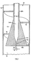
- the cyclone separator shown therein has a separating chamber 25 which has its surface defined as an axially extending surface of revolution in turn defined by the inner surface of an outer casing 37.
- the separating chamber is of generally tapered form, tapering from a larger diameter end 10a to a smaller diameter end 10b.
- the separating chamber 25 is shown as being formed in accordance with the teachings of the aforementioned United States patent 4,237,006, Australian patent application 84713/79 or International application PCT/AU83/00028.
- the separating chamber 25 has a first portion 12 of diameter d1 and length l1 this being of generally constant diameter throughout its length, a tapered portion 12a of frusto-conical configuration which tapers from diameter d1 to a lesser diameter d2, a second, tapered, portion 14 of length l2, diameter d2 at its larger end and diameter d3 at its smaller end, the second portion 14 leading to a third portion 16 of diameter d3 having a substantially constant diameter throughout its length.
- portion 12 leads, in the direction away from portion 14, to an inlet duct 70, defined within a hollow casing 72 of cylindrical form, which casing constitutes a continuation of the casing 37 (where this defines portion 12 of the separator) and having the same diameter thereas.
- the inner surface of casing 72 defines the outer surface of the duct 70.
- the inner surface of the duct 70 is defined by the outer surface of a tapered body 80 having frusto-conical body portion 80a positioned within the casing 72 and arranged coaxially therewith, with its larger diameter end, having diameter d a , at the end of duct 70 adjacent portion 12 of the separating chamber, and tapering in the direction away from the separating chamber to a diameter d b .
- the body 80 further includes a cylindrical end portion 80b, coining body portion 80a, at its smaller diameter end, this likewise being coaxial with casing 72.
- the body 80 At its larger diameter end, the body 80 has a transverse face 80c, ( Figures 2 and 3) which forms an end face of separating chamber 25, at the larger diameter end thereof.
- Body 80 also has therewithin an axial overflow outlet 34 in the form of a generally elongate cylindrical duct which opens to the separating chamber 25 via an overflow outlet opening 32 of diameter d0 formed in face 80c.
- annular inlet opening 29 Between the body 80, at its larger diameter end, and the inner periphery of the separating chamber 12 immediately adjacent thereto, there is defined an annular inlet opening 29.
- a baffle in the form of a helical flight 90, extends for several turns around body 80 and is sealingly secured, at the inner edge thereof, to the outer periphery of the body 80 and, at its outer edge, to the inner periphery of the casing 72. Flight 90 terminates at a transverse edge 90a, at the larger diameter end of the body 80.
- the duct 70 is defined at its outer periphery by the inner surface or casing 72, and at its inner periphery by the outer surface of the body 80. In view of the interposition of the flight 90 between these components, the duct 70 further defines a helical inlet passage 75.
- the duct 70 which is of annular and generally helical form, decreases in cross-sectional area in the direction towards the separating chamber 25.
- liquid mixture to be separated is admitted into the duct 70 and, because of the presence of the flight 90, is caused to execute a helical motion, moving within the passage 75 to the annular inlet opening 29, at which it enters the separating chamber 25 with a component of motion in the axial direction of the separating chamber and with a, further, tangential component.
- the separator 10 operates in a similar fashion to the separators described in the aforementioned prior patent specifications.
- the mixture travels in helical fashion lengthwise along the separating chamber.
- the more dense component of the mixture continues this motion to eventually exit chamber 25 via an underflow outlet 23 at end 10b of the separator.
- the less dense component forms an inner axial core which is driven in the opposite direction to flow to overflow outlet opening 32, passing thereinto and exiting from the separator via the overflow outlet 34.
- the separator may be constructed in accordance with the following dimensional constraints: l2/d2 ⁇ 6 , such as 6 ⁇ l2/d2 ⁇ 25 d0/d2 ⁇ 0.25 , such as d0/d2 ⁇ 0.1 or ⁇ 0.1 d1 > d2 d2 > d3
- l1, l2, l3, d1, d2, d3 and d0 have the meanings abovementioned
- a i is the inlet area of the passage 75 at the cross-section where the flight 90 terminates, i.e., at the transverse plane containing edge 90a.
- the half angle of the taper of the second portion 14 may be 20′ to 3°, such as 1°.
- Portion 12a is optional. If provided, it may have a half angle, ⁇ of 5° ⁇ ⁇ ⁇ 30° such as 10°.
- a further portion may be added to the separating chamber 25 at the end 10b thereof, such as being of frusto-conical form, in order to improve operation of the separator.
- the overflow outlet may be of two part form having a first portion 34a adjacent to and defining opening 32, this being of lesser diameter than a second portion 34b of the overflow outlet which is further from the separating chamber 25.
- the portions 34a, 34b may be interconnected by a tapered portion 34c.
- the larger diameter portion 34b having a diameter designated d l .
- Figures 4 and 5 show arrangements similar to that in Figure 1 and like reference numerals denote like components in each of these Figures.
- the separators have two helical flights 90 instead of the single such flight provided in Figures 1 to 3.
- the term A i is intended to be taken to be a measure of the total inlet area, whether presented by one, two or more passages 75.
- the arrangement of Figure 4 has two inlet openings 29a of "half annular" arcuate form defined at the location where flights 90 end, and between the outer periphery of body 80 and the inner periphery of casing 72a.
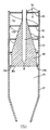
- the arrangement of Figure 5, is designed for side entry of the inlet liquid rather than end entry as in the arrangements of Figures 1 to 4.
- the casing 37 defining separating chamber 25 is made of the same diameter as the largest diameter d a of the body 80 and joins the body at its largest diameter end.
- the casing 72 defining ducts 70 is however of larger diameter than the diameter d a and is extended in the direction towards the underflow outlet of the separating chamber by a further hollow cylindrical end portion 72a which may as shown be of the same diameter as the remainder of casing 72.
- Casing portion 72a is thus adjacent and concentrically positioned in spaced relationship around an end portion 37a of casing 37 to define an annular space therebetween.
- the casing portions 37a, 72a are joined by an outwardly stepped wall portion 10c of the separator.
- the flights 90 are extended for one half of a convolution from body 80 towards the overflow outlet of the separating chamber, in the space between the casing portions 37a, 72a so that the passages 75 are likewise so extended.
- Inlet ports 95 are provided through the side wall of casing portion 37a to permit inflow of inlet liquid from respective passages 75 into separating chamber 25.
- parts 97 of the side wall of casing portion 72a may be formed of gradually decreasing diameter, as the inlets 95 are approached, to form involute-like inlet duct portions leading to the inlets 95.
- the construction is again similar to those previously described.
- the inlet duct 70 is defined within casing 72, as before, and the body 80 is again provided.
- the or each flight 90 is in this case not affixed to the casing 72, the flights being arranged to be rotatable axially of the duct 70. More particularly, they may, as shown, be formed as involute type blades 100 on the body 80, the body and blades being together rotatable about the axis of the separator.
- suitable drive means such as a motor drive to rotate the body and blades about the axis of the body, the inlet liquid flowing into separating chamber 25 via duct 70 may have a desired degree of tangential motion imparted thereto.
- the blades 100 may be formed on another body coaxially rotatable around body 80.
Landscapes
- Physics & Mathematics (AREA)
- Thermal Sciences (AREA)
- Chemical & Material Sciences (AREA)
- Chemical Kinetics & Catalysis (AREA)
- Fluid Mechanics (AREA)
- Geometry (AREA)
- Cyclones (AREA)
Claims (8)
- Trennschleuder, um damit zwei Flüssigkeitskomponenten, von denen eine eine höhere Dichte und die andere eine geringere Dichte aufweist, voneinander zu trennen, wenn diese in gemischter Form einer Trennkammer der Schleuder zugeführt werden, wobei die Trennkammer (25) eine im allgemeinen konisch ausgeführte Form aufweist, die von einem einen größeren Durchmesser aufweisenden Ende (10a) zu einem einen kleineren Durchmesser aufweisenden Ende (10b) konisch zuläuft und als eine sich axial erstreckende Drehoberfläche ausgebildet ist, die Trennkammer (25) mit einem für die weniger dichte Komponente vorgesehenen Überlaufaustritt (34), der an dem den größeren Durchmesser aufweisenden Ende (10a) angeordnet ist, und mit einem Unterlaufaustritt (33), der an dem den kleineren Durchmesser aufweisenden Ende (10b) vorgesehen ist, damit dort die dichtere Komponente austreten kann, sowie mit einem Eintrittsmittel ausgestattet ist, um so die Mischung an einer Stelle zumindest in Richtung auf das genannte, den größeren Durchmesser aufweisende Ende (10a) mit einer tangentialen Bewegungskomponente in die Trennkammer (25) einzuführen, wobei das Eintrittsmittel in Form eines sich axial erstreckenden Eintrittskanals (20) ausgebildet ist, der an dem genannten, den größeren Durchmesser aufweisenden Ende (10a) der Kammer in die Trennkammer (25) eintritt, der Eintrittskanal (20) mit einem Strömungsleitmittel (90) ausgestattet ist, um die Strömung mit der genannten tangentialen Bewegungskomponente axial in die Trennkammer (25) einzuleiten, wobei das genannte Eintrittsmittel weiterhin einen zylindrischen Abschnitt (72) umfaßt, der eine äußere Grenzoberfläche innerhalb des genannten Eintrittskanals (70) bildet, und innerhalb dieses zylindrischen Abschnittes (72) ein stumpfkegelig geformter, konisch zulaufender Abschnitt (80) koaxial angeordnet ist, um so eine innere Grenzoberfläche innerhalb des genannten Kanals (70) vorzusehen, wobei der genannte konisch zulaufende Abschnitt (80) sein den größeren Durchmesser aufweisendes Ende am Ende des Eintrittskanals (70) in nächster Nähe zur Trennkammer (25) besitzt, dadurch gekennzeichnet, daß das genannte, den großen Durchmesser aufweisende Ende des genannten konisch zulaufenden Abschnittes (80) mit Ausnahme eines einen kleinen Durchmesser aufweisenden axialen Durchganges (32), der für eine Flüssigkeitsverbindung zwischen der Trennkammer (25) und dem Überlaufaustritt (34) sorgt, geschlossen ist.
- Trennschleuder nach Anspruch 1, wobei das Strömungsleitmittel ein Prallblech (90) umfaßt, das schneckenförmig ausgebildet sein kann und vorzugsweise ein Prallblech aus einer Mehrzahl von schneckenförmig ausgebildeten Prallblechen darstellt.
- Trennschleuder nach Anspruch 1, wobei der Eintrittskanal (70) sich zu einer oder mehreren Eintrittsöffnungen (29) in einem umgebenden, koaxialen Verhältnis zum Überlaufaustritt erstreckt.
- Trennschleuder nach Anspruch 1, wobei ein schneckenförmiger Eintrittsdurchgang (75) im genannten Kanal (70) in Form einer Schneckenwendel (90) ausgebildet ist, die im genannten Kanal (70) angeordnet ist und das genannte Strömungsleitmittel bildet.
- Trennschleuder nach Anspruch 4, wobei der genannte Kanal (70) über seine Länge einen im wesentlichen konstanten Außendurchmesser, jedoch einen stumpfkegeligen Wandinnendurchmesser aufweist, der in Richtung der Eintrittsströmung zur Trennkammer (25) hin zunimmt.
- Trennschleuder nach Anspruch 4 oder Anspruch 5, wobei der genannte Eintrittskanal (70) sich zur genannten Trennkammer (25) hin an einer oder mehreren Stellen, die radial mit Abstand zum Überlaufaustritt (34) angeordnet sind, sowie an einer Endwand der Schleuder öffnet, in der der Überlaufaustritt (34) sich zur Trennkammer (25) hin öffnet.
- Trennschleuder nach Anspruch 4 oder Anspruch 5, wobei der Eintrittskanal (70) sich zur Trennkammer hin über darin ausgebildete Seiteneintrittsöffnungen (95) öffnet.
- Trennschleuder nach Anspruch 1, wobei das genannte Strömungsleitmittel einen axial drehbaren Körper (80) umfaßt, der im Eintrittskanal (70) angeordnet und mit Schaufeln (100) ausgestattet ist.
Applications Claiming Priority (3)
| Application Number | Priority Date | Filing Date | Title |
|---|---|---|---|
| AUPI557187 | 1987-11-24 | ||
| AU5571/87 | 1987-11-24 | ||
| PCT/AU1988/000456 WO1989004726A1 (en) | 1987-11-24 | 1988-11-24 | Cyclone separator |
Publications (3)
| Publication Number | Publication Date |
|---|---|
| EP0341282A1 EP0341282A1 (de) | 1989-11-15 |
| EP0341282A4 EP0341282A4 (de) | 1990-04-09 |
| EP0341282B1 true EP0341282B1 (de) | 1994-05-11 |
Family
ID=3772597
Family Applications (1)
| Application Number | Title | Priority Date | Filing Date |
|---|---|---|---|
| EP88909966A Expired - Lifetime EP0341282B1 (de) | 1987-11-24 | 1988-11-24 | Trennschleuder |
Country Status (7)
| Country | Link |
|---|---|
| US (1) | US4966703A (de) |
| EP (1) | EP0341282B1 (de) |
| AU (1) | AU606774B2 (de) |
| CA (1) | CA1298211C (de) |
| DE (1) | DE3889535D1 (de) |
| MY (1) | MY103493A (de) |
| WO (1) | WO1989004726A1 (de) |
Families Citing this family (38)
| Publication number | Priority date | Publication date | Assignee | Title |
|---|---|---|---|---|
| JP3019358B2 (ja) * | 1990-04-10 | 2000-03-13 | ミノルタ株式会社 | 複写機管理装置 |
| FR2663238B1 (fr) * | 1990-06-18 | 1992-09-18 | Inst Francais Du Petrole | Procede et dispositif de separation entre une phase fluide continue et une phase dispersee, et application. |
| US5229014A (en) * | 1991-12-18 | 1993-07-20 | Vortech International, Inc. | High efficiency centrifugal separation apparatus and method using impeller |
| FR2697447B1 (fr) * | 1992-11-05 | 1995-01-13 | Inst Francais Du Petrole | Dispositif et procédé pour effectuer la séparation de phases par filtration et centrifugation. |
| DE19650407A1 (de) * | 1996-12-05 | 1998-06-10 | Kevin Business Corp | Blut-Gas-Trennverfahren und -Trennvorrichtung |
| DE19650406A1 (de) | 1996-12-05 | 1998-06-18 | Kevin Business Corp | Blutabsaugvorrichtung |
| GB9625999D0 (en) * | 1996-12-13 | 1997-01-29 | Hesse Wayne W | Hydrocyclone |
| DE19719555A1 (de) * | 1997-05-09 | 1998-11-12 | Kevin Business Corp | Verfahren und Vorrichtung zum Ausscheiden von Gas aus gashaltigem Blut |
| AUPP554698A0 (en) * | 1998-08-28 | 1998-09-17 | University Of Queensland, The | Cyclone separation apparatus |
| AU741814B2 (en) * | 1998-08-28 | 2001-12-13 | University Of Queensland, The | Cyclone |
| GB2383545B (en) * | 1999-04-15 | 2003-12-10 | Hydro Int Plc | Hydrodynamic vortex separator |
| GB2353236A (en) * | 1999-08-17 | 2001-02-21 | Baker Hughes Ltd | Cyclone separator with multiple baffles of distinct pitch |
| KR20020041691A (ko) * | 2000-11-28 | 2002-06-03 | 홍성욱 | 사이클론 슬러지 분리기 및 이 분리기가 구비된 전해처리시스템 |
| DE10127820A1 (de) * | 2001-06-07 | 2002-12-12 | Bosch Gmbh Robert | Ölabscheidevorrichtung für Kurbelgehäusegase einer Verbrennungskraftmaschine |
| US6793814B2 (en) * | 2002-10-08 | 2004-09-21 | M-I L.L.C. | Clarifying tank |
| NL1022581C2 (nl) * | 2003-02-04 | 2004-08-05 | Cds Engineering B V | Scheidingscycloon en werkwijze voor het scheiden van een mengsel. |
| JP4646971B2 (ja) * | 2004-03-08 | 2011-03-09 | ラインツ−ディクトゥングス−ゲーエムベーハー | 液体分離装置 |
| NL1028238C2 (nl) * | 2005-02-10 | 2006-08-11 | Flash Technologies N V | Cycloonscheider en werkwijze voor het scheiden van een mengsel van vaste stof, vloeistof en/of gas. |
| GB2462210B (en) * | 2006-06-16 | 2010-12-22 | Cameron Int Corp | Separator and method of separation |
| KR100652840B1 (ko) | 2006-06-28 | 2006-12-01 | 고균희 | 사이클론을 이용한 물 정화장치 |
| KR100784733B1 (ko) | 2006-06-28 | 2007-12-12 | 고균희 | 와류 발생용 원통체 |
| CN101524610B (zh) * | 2008-03-07 | 2012-07-04 | 中国石油大学(北京) | 带有锥型隔流筒的高效提升管出口旋流快分设备 |
| US9623196B2 (en) * | 2011-08-30 | 2017-04-18 | Carefusion 303, Inc. | System and method for trapping air bubbles |
| GB201213385D0 (en) * | 2012-07-27 | 2012-09-12 | Flame Marine Ltd | Method and apparatus for collecting samples of oil from marine engines |
| CN103433156B (zh) * | 2013-09-02 | 2015-05-27 | 无锡恒诚硅业有限公司 | 一种用于白炭黑生产的旋风分离器的叶片 |
| CN103588260B (zh) * | 2013-11-11 | 2015-03-11 | 上海华畅环保设备发展有限公司 | 液-固微旋流分离器长周期连续稳定运行的倒置倾斜安装方法与装置 |
| GB2524743A (en) * | 2014-03-31 | 2015-10-07 | Nano Porous Solutions Ltd | Apparatus for contaminant reduction in a stream of compressed gas |
| DE102015008525A1 (de) * | 2014-08-12 | 2016-02-18 | Mann + Hummel Gmbh | Fliehkraftabscheider und Filteranordnung |
| US10661210B2 (en) * | 2015-09-15 | 2020-05-26 | Miniature Precision Components, Inc. | Oil separator including spiral members defining helical flow paths |
| CN105289117B (zh) * | 2015-12-08 | 2017-11-10 | 江苏揽山环境科技股份有限公司 | 除雾器 |
| CN105289114B (zh) * | 2015-12-08 | 2017-07-04 | 江苏揽山环境科技股份有限公司 | 除雾除尘叶片组 |
| JP7005880B2 (ja) | 2017-06-21 | 2022-01-24 | バイオドライングテック エスピーエー | 固体粒子を分離する加速サイクロン |
| CA3027567C (en) * | 2017-12-20 | 2023-02-21 | Miniature Precision Components, Inc. | Oil separator including spiral members defining helical flow paths |
| EP4180111B1 (de) * | 2018-05-18 | 2024-11-13 | Donaldson Company, Inc. | Vorreinigungsanordnung zur verwendung bei der luftfilterung |
| DE102019119349A1 (de) * | 2019-07-17 | 2021-01-21 | Krones Aktiengesellschaft | Drall- und Drosselkörper für ein Einlaufventil eines Entgasungsbehälters und Verfahren zum Einleiten einer Flüssigkeit in einen Entgasungsbehälter |
| NO344801B1 (en) * | 2019-09-06 | 2020-05-04 | Stauper Offshore As | A separation apparatus with insert |
| CA3159191A1 (en) * | 2019-10-31 | 2021-05-06 | Mott Corporation | Two-phase separator devices incorporating inertial separation and porous media extraction |
| CN113351385A (zh) * | 2021-05-13 | 2021-09-07 | 中国石油大学(北京) | 换热分离一体化旋风分离装置 |
Family Cites Families (14)
| Publication number | Priority date | Publication date | Assignee | Title |
|---|---|---|---|---|
| US2413324A (en) * | 1939-06-09 | 1946-12-31 | Holzwarth Gas Turbine Co | Gas purifying apparatus |
| FR892950A (fr) * | 1943-02-08 | 1944-05-24 | Delbag Deutsche Luftfilter Bau | Couronne de palettes pour épurateurs à force centrifuge |
| US2667944A (en) * | 1949-12-10 | 1954-02-02 | Combustion Eng | Cyclone separator |
| BE513612A (de) * | 1952-08-06 | |||
| US2754970A (en) * | 1953-06-10 | 1956-07-17 | Ross Robert Dalrymple | Fluid separator |
| NL110597C (de) * | 1956-12-06 | |||
| US2936043A (en) * | 1957-01-09 | 1960-05-10 | Cottrell Res Inc | Cyclonic dust collector |
| DE1081424B (de) * | 1958-01-21 | 1960-05-12 | Thomas Fischer Dipl Ing | Verfahren und Vorrichtung zur Abscheidung von fluessigen oder festen Stoffen aus Gasen oder Fluessigkeiten |
| GB920230A (en) * | 1961-02-07 | 1963-03-06 | Coopers Mech Joints | Improvements in or relating to cyclones for removing solids from gas |
| US3407575A (en) * | 1967-12-08 | 1968-10-29 | Krizman John | Through-flow spark arrester |
| US3543485A (en) * | 1968-09-23 | 1970-12-01 | Universal Oil Prod Co | Centrifugal particle separator |
| FI54436C (fi) * | 1976-05-14 | 1978-12-11 | Enso Gutzeit Oy | Hydrocyklon |
| CA1063974A (en) * | 1977-01-26 | 1979-10-09 | Elast-O-Cor Products And Engineering Limited | Hydrocyclone system including axial feed and tangential transition sections |
| US4832709A (en) * | 1983-04-15 | 1989-05-23 | Allied Signal, Inc. | Rotary separator with a bladeless intermediate portion |
-
1988
- 1988-11-24 EP EP88909966A patent/EP0341282B1/de not_active Expired - Lifetime
- 1988-11-24 DE DE3889535T patent/DE3889535D1/de not_active Expired - Lifetime
- 1988-11-24 WO PCT/AU1988/000456 patent/WO1989004726A1/en not_active Ceased
- 1988-11-24 MY MYPI88001350A patent/MY103493A/en unknown
- 1988-11-24 US US07/392,969 patent/US4966703A/en not_active Expired - Fee Related
- 1988-11-24 CA CA000584078A patent/CA1298211C/en not_active Expired - Fee Related
- 1988-11-24 AU AU27805/89A patent/AU606774B2/en not_active Ceased
Also Published As
| Publication number | Publication date |
|---|---|
| WO1989004726A1 (en) | 1989-06-01 |
| DE3889535D1 (de) | 1994-06-16 |
| EP0341282A1 (de) | 1989-11-15 |
| CA1298211C (en) | 1992-03-31 |
| US4966703A (en) | 1990-10-30 |
| AU2780589A (en) | 1989-06-14 |
| EP0341282A4 (de) | 1990-04-09 |
| MY103493A (en) | 1993-06-30 |
| AU606774B2 (en) | 1991-02-14 |
Similar Documents
| Publication | Publication Date | Title |
|---|---|---|
| EP0341282B1 (de) | Trennschleuder | |
| US6190543B1 (en) | Cyclonic separator | |
| US20060162299A1 (en) | Separation apparatus | |
| US5017288A (en) | Cyclone separator | |
| US5858237A (en) | Hydrocyclone for separating immiscible fluids and removing suspended solids | |
| AU612561B2 (en) | Cyclone separator | |
| EP0600628B1 (de) | Dekanterzentrifuge | |
| EP0401276A1 (de) | Trennverfahren für flüssigkeiten | |
| WO1985001454A1 (en) | Cyclone separator | |
| CA1197478A (en) | Cyclone separators | |
| US20040069705A1 (en) | Long free vortex, multi-compartment separation chamber cyclone apparatus | |
| US5049277A (en) | Cyclone separator | |
| HU193792B (en) | Method and apparatus for separating individual phases of multiple-phase flowable media | |
| US5009784A (en) | Cyclone separator with oppositely directed separating chambers | |
| WO1989011339A1 (en) | Cyclone separator apparatus | |
| EP0480921A4 (en) | Cyclone separator | |
| SU1674973A1 (ru) | Циклон | |
| EP2910924B1 (de) | Nichtmetallisches Rückstandsüberwachungssystem | |
| US20020166820A1 (en) | Separation device and method comprising a tubular electrocoalescer | |
| EP0815944A2 (de) | Zyklonabscheider | |
| GB2156708A (en) | Improvements in or relating to separation | |
| WO1987006159A1 (en) | Apparatus for separating mixtures | |
| AU7087887A (en) | Cyclone separator | |
| JPH0696134B2 (ja) | 渦流形遠心分離機 | |
| ITFI980114A1 (it) | Sistema di lavaggio dell'olio di oliva mediante addizione di acqua nell'estrattore centrifugo |
Legal Events
| Date | Code | Title | Description |
|---|---|---|---|
| PUAI | Public reference made under article 153(3) epc to a published international application that has entered the european phase |
Free format text: ORIGINAL CODE: 0009012 |
|
| 17P | Request for examination filed |
Effective date: 19890717 |
|
| AK | Designated contracting states |
Kind code of ref document: A1 Designated state(s): DE FR GB IT NL |
|
| A4 | Supplementary search report drawn up and despatched |
Effective date: 19900409 |
|
| 17Q | First examination report despatched |
Effective date: 19910917 |
|
| GRAA | (expected) grant |
Free format text: ORIGINAL CODE: 0009210 |
|
| AK | Designated contracting states |
Kind code of ref document: B1 Designated state(s): DE FR GB IT NL |
|
| PG25 | Lapsed in a contracting state [announced via postgrant information from national office to epo] |
Ref country code: IT Free format text: LAPSE BECAUSE OF FAILURE TO SUBMIT A TRANSLATION OF THE DESCRIPTION OR TO PAY THE FEE WITHIN THE PRE;WARNING: LAPSES OF ITALIAN PATENTS WITH EFFECTIVE DATE BEFORE 2007 MAY HAVE OCCURRED AT ANY TIME BEFORE 2007. THE CORRECT EFFECTIVE DATE MAY BE DIFFERENT FROM THE ONE RECORDED.SCRIBED TIME-LIMIT Effective date: 19940511 Ref country code: NL Effective date: 19940511 Ref country code: DE Effective date: 19940511 Ref country code: FR Effective date: 19940511 |
|
| REF | Corresponds to: |
Ref document number: 3889535 Country of ref document: DE Date of ref document: 19940616 |
|
| RAP2 | Party data changed (patent owner data changed or rights of a patent transferred) |
Owner name: CONOCO SPECIALTY PRODUCTS INC. |
|
| EN | Fr: translation not filed | ||
| NLV1 | Nl: lapsed or annulled due to failure to fulfill the requirements of art. 29p and 29m of the patents act | ||
| PLBE | No opposition filed within time limit |
Free format text: ORIGINAL CODE: 0009261 |
|
| STAA | Information on the status of an ep patent application or granted ep patent |
Free format text: STATUS: NO OPPOSITION FILED WITHIN TIME LIMIT |
|
| 26N | No opposition filed | ||
| PGFP | Annual fee paid to national office [announced via postgrant information from national office to epo] |
Ref country code: GB Payment date: 19971027 Year of fee payment: 10 |
|
| PG25 | Lapsed in a contracting state [announced via postgrant information from national office to epo] |
Ref country code: GB Free format text: LAPSE BECAUSE OF NON-PAYMENT OF DUE FEES Effective date: 19981124 |
|
| GBPC | Gb: european patent ceased through non-payment of renewal fee |
Effective date: 19981124 |