EP0341115B1 - Vorrichtung zum Einführen einer dosierten Menge eines Produktes in einem geschlossenen Raum - Google Patents
Vorrichtung zum Einführen einer dosierten Menge eines Produktes in einem geschlossenen Raum Download PDFInfo
- Publication number
- EP0341115B1 EP0341115B1 EP89401104A EP89401104A EP0341115B1 EP 0341115 B1 EP0341115 B1 EP 0341115B1 EP 89401104 A EP89401104 A EP 89401104A EP 89401104 A EP89401104 A EP 89401104A EP 0341115 B1 EP0341115 B1 EP 0341115B1
- Authority
- EP
- European Patent Office
- Prior art keywords
- capsule
- orifice
- parts
- enclosure
- collar
- Prior art date
- Legal status (The legal status is an assumption and is not a legal conclusion. Google has not performed a legal analysis and makes no representation as to the accuracy of the status listed.)
- Expired - Lifetime
Links
- 239000002775 capsule Substances 0.000 claims description 59
- 238000007789 sealing Methods 0.000 claims description 3
- 239000011295 pitch Substances 0.000 claims 1
- 241000196324 Embryophyta Species 0.000 description 1
- 240000008042 Zea mays Species 0.000 description 1
- 238000004140 cleaning Methods 0.000 description 1
- 230000007812 deficiency Effects 0.000 description 1
- 238000010586 diagram Methods 0.000 description 1
- 238000009434 installation Methods 0.000 description 1
- 230000000717 retained effect Effects 0.000 description 1
- 230000009466 transformation Effects 0.000 description 1
- XLYOFNOQVPJJNP-UHFFFAOYSA-N water Substances O XLYOFNOQVPJJNP-UHFFFAOYSA-N 0.000 description 1
Images

Classifications
-
- B—PERFORMING OPERATIONS; TRANSPORTING
- B65—CONVEYING; PACKING; STORING; HANDLING THIN OR FILAMENTARY MATERIAL
- B65D—CONTAINERS FOR STORAGE OR TRANSPORT OF ARTICLES OR MATERIALS, e.g. BAGS, BARRELS, BOTTLES, BOXES, CANS, CARTONS, CRATES, DRUMS, JARS, TANKS, HOPPERS, FORWARDING CONTAINERS; ACCESSORIES, CLOSURES, OR FITTINGS THEREFOR; PACKAGING ELEMENTS; PACKAGES
- B65D81/00—Containers, packaging elements, or packages, for contents presenting particular transport or storage problems, or adapted to be used for non-packaging purposes after removal of contents
- B65D81/32—Containers, packaging elements, or packages, for contents presenting particular transport or storage problems, or adapted to be used for non-packaging purposes after removal of contents for packaging two or more different materials which must be maintained separate prior to use in admixture
- B65D81/3205—Separate rigid or semi-rigid containers joined to each other at their external surfaces
- B65D81/3211—Separate rigid or semi-rigid containers joined to each other at their external surfaces coaxially and provided with means facilitating admixture
-
- A—HUMAN NECESSITIES
- A01—AGRICULTURE; FORESTRY; ANIMAL HUSBANDRY; HUNTING; TRAPPING; FISHING
- A01M—CATCHING, TRAPPING OR SCARING OF ANIMALS; APPARATUS FOR THE DESTRUCTION OF NOXIOUS ANIMALS OR NOXIOUS PLANTS
- A01M7/00—Special adaptations or arrangements of liquid-spraying apparatus for purposes covered by this subclass
- A01M7/0089—Regulating or controlling systems
- A01M7/0092—Adding active material
-
- Y—GENERAL TAGGING OF NEW TECHNOLOGICAL DEVELOPMENTS; GENERAL TAGGING OF CROSS-SECTIONAL TECHNOLOGIES SPANNING OVER SEVERAL SECTIONS OF THE IPC; TECHNICAL SUBJECTS COVERED BY FORMER USPC CROSS-REFERENCE ART COLLECTIONS [XRACs] AND DIGESTS
- Y10—TECHNICAL SUBJECTS COVERED BY FORMER USPC
- Y10S—TECHNICAL SUBJECTS COVERED BY FORMER USPC CROSS-REFERENCE ART COLLECTIONS [XRACs] AND DIGESTS
- Y10S215/00—Bottles and jars
- Y10S215/08—Mixing
Definitions
- the present invention relates to a device for introducing a metered quantity of a product inside an enclosure without said product being able to spread outside the enclosure.
- the current trend in agriculture is to use treatment products which are delivered in a concentrated form and diluted on the spot with water in a large tank, just before dispersing on the ground or on plants.
- the treatment products, in the concentrated state can be dangerous for the personnel of use or for the environment. They must therefore be contained in sealed containers before use, and the empty container, which still contains small quantities of product, must be closed after use to be treated in a special installation. This amounts to saying that the container containing the concentrated product must be closed as long as it is not in relation to the mixing tank, and only open towards the inside of this tank, or else in a specially enclosure scheduled for possible cleaning.
- the device is simple and of a low cost price, and that it can be easily adapted on the existing tanks, with a minimum of transformation of these.
- the device in the cited document has the particularity, among other things, that one of the parts of the capsule is integral with the stopper, so that caps must be stored and handled with a volume considerably greater than the volume of product contained in the capsule, and that the other part of the capsule has the form of a cup open at its upper part, so that the complete release of the product contained can only take place after the fall of this cup in the enclosure .
- the object of the invention is to provide a device which does not have the drawbacks which result from the features which have just been stated.
- the invention provides a device of the type described above and which has the particularity that a part of the capsule has openings which pass through it and which are obstructed by the other part when the two parts are fully screwed , so as to contain said product in a sealed manner in the capsule, these openings opening by the relative unscrewing of the two parts to put the interior of the capsule in communication with the interior of the enclosure.
- the stopper consists of a collar which can be mounted by screwing on the edge of said orifice, and of the capsule itself, a first part of which is integral in rotation with the collar, while the second part of the wall internal of the orifice comprises means cooperating to prevent rotation of the second part.
- the first part of the capsule can be separated from the collar and be clamped between the collar and the edge of the orifice when the cap is screwed on.
- the first part of the capsule comprises a bottom and a cylindrical wall having an opening directed towards the interior of the enclosure when the device is in place, this cylindrical wall externally carrying a flange intended to be clamped between the edge of the orifice and the collar, protrusions or grooves for cooperation with the collar, and an external thread
- the second part of the capsule comprises a bottom and a cylindrical wall having an opening directed opposite to that of the first part, the edge of the cylindrical wall of the first part coming, in the screwed position, in sealed support on the bottom of the second part, and the cylindrical wall of the second part has an internal thread to cooperate with the external thread of the first part, and projections or grooves for cooperation with corresponding reliefs of the internal wall of the orifice, this cylindrical wall further having lights in the vicinity of the bottom.
- means are advantageously provided to prevent the two parts of the capsule from separating when they are divided.
- These means may include two hooks carried by one of the parts and cooperating with one of the projections of the other part of the capsule.
- the device in the case where the internal wall of the orifice is smooth, provision is made for the device to include an adapter which is fixed on the container to extend the orifice, and which carries said reliefs cooperating with projections or grooves of the cylindrical wall of the second part in order to prevent the rotation thereof.
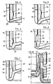
- Figures 1 and 2 relate to a device according to the invention, which is intended to be placed in an orifice of a mixing container.
- the reference 1 designates the wall of the container, and 2 the orifice used.
- the orifice 2 can be a filling orifice, or any other suitable orifice. If it's a drain port, located in the bottom of the container, the top and bottom of Figure 2 will be reversed when using the container.
- the orifice 2 is provided with a neck 3 which has an external thread 4.
- a clamp 5 has an internal thread 6, designed to cooperate with the thread 4 of the container, and an outer collar, with a narrower diameter 7.
- the capsule comprises a first part 8, composed of a bottom 9, and a cylindrical part in the assembly 10. This cylindrical part carries, on its outer face, from top to bottom in FIGS. 1 and 2, ribs 11, a flange 12, intended to be received between the flange 7 of the clamp and the outer edge of the neck 3, and a thread 13 with a pitch opposite to that of the threads 4 and 6.
- the outer end of the cylindrical wall 10 is formed to serve as a sealing surface, as will be explained later.
- the second part of the capsule comprises a bottom 14, and a cylindrical wall 15, into which the cylindrical wall 10 of the first part penetrates.
- the wall 15 has a thread 16 designed to cooperate with the thread 13 of the first part, axial ribs 17, better visible in FIG. 4, and which are intended to cooperate with grooves 18 which are located on the inside wall of the neck 3.
- the wall 15 is traversed by slots 19, intended for the flow of the product contained inside the capsule.
- an adapter provided with such grooves.
- Such an adapter 40 is shown in FIG. 10. It has a female thread 41 allowing it to be screwed onto the thread 4 of the neck and a male thread 42 onto which the internal thread 6 of the clamp will be screwed.
- the mode of use of the device is as follows:
- the capsule filled with concentrated product and closed is supplied by the manufacturer.
- the user inserts it into the clamp 5, taking care to introduce the ribs 11 into corresponding grooves thereof.
- it sets up the assembly, by introducing the ribs 17 of the second part of the capsule into the grooves 18 of the neck of the container, then it tightens the clamp by screwing the thread 6 onto the thread 4.
- the grooves 18 are greatly widened towards the outside of the neck, to facilitate the introduction of the ribs 17.
- the capsule can be recovered by performing a reverse maneuver: the loosening of the collar 5 causes the first and second parts to be screwed in reciprocally, so that when the capsule, it is closed and therefore the remains of concentrated product that it can contain cannot spill outside.
- the reference 20, in Figures 1, 2 and 4 designates safety hooks, carried by the bottom 14 of the second part and which cooperate, in the unscrewing position, with a projection 21, provided on the inner face of the first part. of the capsule. It may happen, in fact, that if the collar 5 has been rotated without the threads 4 and 6 cooperating, while the ribs 17 are already engaged in the grooves 18, there is too much unscrewing of the two parts of the capsule, and that it may fall into the container before the collar 5 is fully tightened. This drawback is avoided by the use of hooks 20.
- FIG. 4 shows four hooks 20. It is clear that this number is not limiting.
- the hooks 20 are preferably placed between the slots 19 so as not to hinder the flow of the product.
- Figures 5 to 8 are detailed diagrams showing how the seal between the two parts of the capsule is achieved.
- the seal is achieved by a circular rib 22, provided on the end of the cylindrical part 10 of the first part, and which enters an annular groove 23 hollowed out in the bottom 14 of the second part.
- a circular rib 22 provided on the end of the cylindrical part 10 of the first part, and which enters an annular groove 23 hollowed out in the bottom 14 of the second part.
- the seal is obtained or supplemented by cooperation of cylindrical, frustoconical surfaces, or in the form of a torus portion.
Landscapes
- Life Sciences & Earth Sciences (AREA)
- Engineering & Computer Science (AREA)
- Insects & Arthropods (AREA)
- Pest Control & Pesticides (AREA)
- Wood Science & Technology (AREA)
- Zoology (AREA)
- Environmental Sciences (AREA)
- Mechanical Engineering (AREA)
- Closures For Containers (AREA)
Claims (7)
dadurch gekennzeichnet, daß ein Teil der Kapsel hindurchgehende Durchlässe (19) aufweist, welche durch das andere Teil gesperrt sind, wenn die beiden Teile (8; 14, 15) bis zum Anschlag geschraubt sind, derart, daß das Produkt in abgedichtetem Zustand in der Kapsel gehalten ist, wobei sich die Durchlässe (19) durch das relative Losschrauben der beiden Teile öffnen, um das Innere der Kapsel in Verbindung mit dem Inneren des Behälters zu bringen.
Applications Claiming Priority (2)
| Application Number | Priority Date | Filing Date | Title |
|---|---|---|---|
| FR8805976A FR2630997B1 (fr) | 1988-05-04 | 1988-05-04 | Dispositif pour introduire une quantite dosee d'un produit a l'interieur d'une enceinte |
| FR8805976 | 1988-05-04 |
Publications (2)
| Publication Number | Publication Date |
|---|---|
| EP0341115A1 EP0341115A1 (de) | 1989-11-08 |
| EP0341115B1 true EP0341115B1 (de) | 1992-01-22 |
Family
ID=9365979
Family Applications (1)
| Application Number | Title | Priority Date | Filing Date |
|---|---|---|---|
| EP89401104A Expired - Lifetime EP0341115B1 (de) | 1988-05-04 | 1989-04-20 | Vorrichtung zum Einführen einer dosierten Menge eines Produktes in einem geschlossenen Raum |
Country Status (4)
| Country | Link |
|---|---|
| US (1) | US4947986A (de) |
| EP (1) | EP0341115B1 (de) |
| DE (1) | DE68900745D1 (de) |
| FR (1) | FR2630997B1 (de) |
Families Citing this family (23)
| Publication number | Priority date | Publication date | Assignee | Title |
|---|---|---|---|---|
| FR2638428B1 (fr) * | 1988-10-28 | 1990-12-28 | Transphyto Sa | Conditionnement pour liquides a epurer |
| AU628139B2 (en) * | 1989-03-27 | 1992-09-10 | American Cyanamid Company | Closed granular chemical handling system |
| US5308347A (en) * | 1991-09-18 | 1994-05-03 | Fujisawa Pharmaceutical Co., Ltd. | Transfusion device |
| US5197636A (en) * | 1992-02-03 | 1993-03-30 | Allergan, Inc. | Fast activation chlorine dioxide delivery apparatus |
| IL113571A (en) * | 1994-05-07 | 1998-09-24 | Horstine Farmery Ltd | valve |
| US5543042A (en) * | 1995-03-30 | 1996-08-06 | Abbott Laboratories | Waste agent reservoir for suction drainage system |
| DE19621774C2 (de) * | 1996-05-30 | 1999-11-18 | Juergen Otto | Vorrichtung zum Zubereiten einer Mischung aus einer Wirksubstanz und einem Verdünnungsmittel sowie Verfahren zum Befüllen einer Kartusche für eine derartige Vorrichtung |
| US5927549A (en) * | 1998-03-20 | 1999-07-27 | Aptargroup, Inc. | Dispensing structure with frangible membrane for separating two products |
| US6289968B1 (en) | 1998-06-15 | 2001-09-18 | Quaker State Investment Corporation | Foldable vehicle sunshade |
| EP0985607A1 (de) * | 1998-07-28 | 2000-03-15 | Guala Closures S.P.A. | Sicherheitsverschluss |
| GB9905948D0 (en) * | 1999-03-15 | 1999-05-05 | Novartis Ag | Valve |
| US6325115B1 (en) | 2000-03-13 | 2001-12-04 | Syngenta Crop Protection, Inc | Valve |
| US6290100B1 (en) | 2000-06-30 | 2001-09-18 | Canberra Corporation | Concentrate cartridge for a diluting and dispensing container |
| KR100593245B1 (ko) * | 2003-12-30 | 2006-06-28 | 조영국 | 이종물질을 실시간 혼합시킬 수 있는 용기의 마개 |
| AU2005304789B2 (en) * | 2004-11-04 | 2012-02-23 | Viz Enterprises, Llc | Multi-chamber container and cap therefor |
| ITMO20050058A1 (it) * | 2005-03-15 | 2006-09-16 | Lameplast Spa | Confezione per prodotti a preparazione estemporanea, particolarmente medicinali, farmaceutici, cosmetici o simili. |
| CN100460288C (zh) * | 2006-07-28 | 2009-02-11 | 刘忠意 | 贮物瓶盖 |
| US8157131B2 (en) | 2008-10-15 | 2012-04-17 | Sim Jae K | Spray bottle with refill cartridge |
| US8302816B2 (en) | 2008-10-15 | 2012-11-06 | Sim Jae K | Spray bottle with refill cartridge |
| US8528784B2 (en) | 2008-10-15 | 2013-09-10 | Jae K. Sim | Spray bottle with refill cartridge |
| EP2292525A1 (de) * | 2009-09-04 | 2011-03-09 | Obrist Closures Switzerland GmbH | Behälterverschlussanordnung |
| US8430137B2 (en) | 2010-08-24 | 2013-04-30 | Jae K. Sim | Refill cap cartridge |
| US9067716B2 (en) | 2011-09-30 | 2015-06-30 | Federico Intriago | Cap assembly for dispensing a dispensable component and method of making and using the same |
Citations (1)
| Publication number | Priority date | Publication date | Assignee | Title |
|---|---|---|---|---|
| EP0235806A2 (de) * | 1986-03-07 | 1987-09-09 | Robert Finke Kommanditgesellschaft | Flaschen-Verschlusskappe für Zwei-Komponenten-Packungen |
Family Cites Families (13)
| Publication number | Priority date | Publication date | Assignee | Title |
|---|---|---|---|---|
| US3237816A (en) * | 1964-11-23 | 1966-03-01 | Shell Oil Co | Measuring dispenser |
| DE2200536A1 (de) * | 1972-01-07 | 1973-07-19 | Zeller Plastik Koehn Graebner | Einrichtung zur getrennten aufbewahrung zweier verschiedener stoffe |
| DE2339388A1 (de) * | 1973-08-03 | 1975-02-13 | Henkel & Cie Gmbh | Behaelterverschluss aus kunststoff mit mischeinrichtung |
| NL7413077A (nl) * | 1974-10-03 | 1976-04-06 | Leer Koninklijke Emballage | Houder met schroefdop. |
| US3924741A (en) * | 1975-03-04 | 1975-12-09 | Gibson Ass Inc | Two-compartment container |
| FR2305364A1 (fr) * | 1975-03-28 | 1976-10-22 | Henkel & Cie Gmbh | Ensemble de bouchage a chambres internes adaptable sur le goulot d'un recipient en tant que doseur-melangeur |
| FR2370650A1 (fr) * | 1976-11-15 | 1978-06-09 | Oreal | Recipient de conditionnement et de distribution comportant au stockage deux compartiments separes |
| ES227573Y (es) * | 1977-03-21 | 1977-11-01 | Tapon recipiente. | |
| DE7736840U1 (de) * | 1977-12-02 | 1978-03-16 | Wella Ag | Behaelter fuer zwei schuettbare Stoffe |
| DK460081A (da) * | 1981-10-19 | 1983-04-20 | Martin Baram | Blandingsaggregat |
| DE3426739A1 (de) * | 1984-07-20 | 1986-01-30 | Robert Finke KG, 5950 Finnentrop | Zwei-komponenten-packung |
| DE3327615C2 (de) * | 1983-07-30 | 1985-08-14 | Robert Finke KG, 5950 Finnentrop | Zwei-Komponenten-Packung |
| DE8606940U1 (de) * | 1986-03-13 | 1987-07-16 | Robert Finke KG, 5950 Finnentrop | Zwei-Komponenten-Packung |
-
1988
- 1988-05-04 FR FR8805976A patent/FR2630997B1/fr not_active Expired - Fee Related
-
1989
- 1989-04-20 EP EP89401104A patent/EP0341115B1/de not_active Expired - Lifetime
- 1989-04-20 DE DE8989401104T patent/DE68900745D1/de not_active Expired - Fee Related
- 1989-05-03 US US07/346,713 patent/US4947986A/en not_active Expired - Fee Related
Patent Citations (1)
| Publication number | Priority date | Publication date | Assignee | Title |
|---|---|---|---|---|
| EP0235806A2 (de) * | 1986-03-07 | 1987-09-09 | Robert Finke Kommanditgesellschaft | Flaschen-Verschlusskappe für Zwei-Komponenten-Packungen |
Also Published As
| Publication number | Publication date |
|---|---|
| US4947986A (en) | 1990-08-14 |
| DE68900745D1 (de) | 1992-03-05 |
| EP0341115A1 (de) | 1989-11-08 |
| FR2630997A1 (fr) | 1989-11-10 |
| FR2630997B1 (fr) | 1990-09-14 |
Similar Documents
| Publication | Publication Date | Title |
|---|---|---|
| EP0341115B1 (de) | Vorrichtung zum Einführen einer dosierten Menge eines Produktes in einem geschlossenen Raum | |
| EP2864216B1 (de) | Ausgabe- und mischvorrichtung | |
| CA2141967C (fr) | Distributeur a plusieurs compartiments pour le stockage et le melange du contenu | |
| FR2680357A1 (fr) | Conditionnement a deux flacons permettant de stocker separement l'un de l'autre deux produits, notamment liquides, et de les melanger au moment de leur utilisation. | |
| FR2732316A1 (fr) | Distributeur pour le soutirage d'un liquide d'un recipient | |
| EP0354111A1 (de) | Verpackungsvorrichtung für eine gebrauchsfertige flüssige Substanz, die aus einer konzentrierten Substanz hergestellt ist und Verfahren zu ihrer Verwendung | |
| FR2765861A1 (fr) | Dispositif pour le conditionnement separe de deux composants et procede de fabrication | |
| EP0297967A1 (de) | Verschlussanordnung mit einem Ausgiesser und einer Dosierkappe mit einer Ausgusstülle | |
| CA2299595C (fr) | Conditionnement pour effectuer le melange d'un produit a plusieurs composantes | |
| EP0999817A1 (de) | Mehrkammersaugflasche | |
| EP0238371A1 (de) | Behälter mit einer viskosen Flüssigkeit, die beim ersten Verbrauch mit einem Zusatz versehen werden kann | |
| EP3053848B1 (de) | Vorrichtung, die einen ersten behälter zur montage auf einen zweiten behälter für das mischen des inhalts jedes dieser zwei behälter umfasst und flasche damit | |
| CA2481798A1 (fr) | Dispositif de bouchage, recipient equipe d'un tel dispositif et procede de fabrication d'un tel dispositif | |
| WO1989000959A1 (fr) | Dispositif pour conserver une substance destinee a etre melangee ulterieurement au contenu d'un recipient a goulot | |
| EP2146908B1 (de) | Behälterkappe mit zusätzlicher aufnahmekapazität | |
| EP0011575A1 (de) | Verschluss mit festgestellter Verschlussposition | |
| EP0522426B1 (de) | Verschluss einer mit einer Sicherung versehenen Öffnung, insbesondere zum Schliessen einer Öffnung eines Behälters für Chemie-, Öl- oder dergleichen Produkte | |
| FR2896776A1 (fr) | Dispositif pour larguer une substance dans un contenant | |
| EP0064932B1 (de) | Trinkbecher zur Mischung von zwei Bestandteilen im Moment des Gebrauchs | |
| FR3053032A1 (fr) | Capsule distributrice a molettte reservoir pour gelules ou comprimes | |
| FR2636310A1 (fr) | Bouchon distributeur en deux pieces a l'epreuve des enfants et emballage a recipient et bouchon | |
| FR2631935A1 (fr) | Bouchon-verseur en matiere synthetique | |
| FR2729372A1 (fr) | Conditionnement a deux compartiments, muni de moyens de melange et de distribution de produit | |
| FR2534558A2 (fr) | Capsule porte-reducteur | |
| EP0618876A1 (de) | GEHAÜSE UND NACHFÜLLEINHEIT FÜR FlÜSSIGE, PASTÖSE ODER PULVERFöRMIGE SUBSTANZEN |
Legal Events
| Date | Code | Title | Description |
|---|---|---|---|
| PUAI | Public reference made under article 153(3) epc to a published international application that has entered the european phase |
Free format text: ORIGINAL CODE: 0009012 |
|
| 17P | Request for examination filed |
Effective date: 19890512 |
|
| AK | Designated contracting states |
Kind code of ref document: A1 Designated state(s): DE GB |
|
| 17Q | First examination report despatched |
Effective date: 19910408 |
|
| GRAA | (expected) grant |
Free format text: ORIGINAL CODE: 0009210 |
|
| AK | Designated contracting states |
Kind code of ref document: B1 Designated state(s): DE GB |
|
| REF | Corresponds to: |
Ref document number: 68900745 Country of ref document: DE Date of ref document: 19920305 |
|
| GBT | Gb: translation of ep patent filed (gb section 77(6)(a)/1977) | ||
| PLBE | No opposition filed within time limit |
Free format text: ORIGINAL CODE: 0009261 |
|
| STAA | Information on the status of an ep patent application or granted ep patent |
Free format text: STATUS: NO OPPOSITION FILED WITHIN TIME LIMIT |
|
| 26N | No opposition filed | ||
| PGFP | Annual fee paid to national office [announced via postgrant information from national office to epo] |
Ref country code: DE Payment date: 20010409 Year of fee payment: 13 |
|
| PGFP | Annual fee paid to national office [announced via postgrant information from national office to epo] |
Ref country code: GB Payment date: 20010412 Year of fee payment: 13 |
|
| REG | Reference to a national code |
Ref country code: GB Ref legal event code: IF02 |
|
| PG25 | Lapsed in a contracting state [announced via postgrant information from national office to epo] |
Ref country code: GB Free format text: LAPSE BECAUSE OF NON-PAYMENT OF DUE FEES Effective date: 20020420 |
|
| PG25 | Lapsed in a contracting state [announced via postgrant information from national office to epo] |
Ref country code: DE Free format text: LAPSE BECAUSE OF NON-PAYMENT OF DUE FEES Effective date: 20021101 |
|
| GBPC | Gb: european patent ceased through non-payment of renewal fee |
Effective date: 20020420 |