EP0341083A2 - Raupenrad - Google Patents
Raupenrad Download PDFInfo
- Publication number
- EP0341083A2 EP0341083A2 EP89304577A EP89304577A EP0341083A2 EP 0341083 A2 EP0341083 A2 EP 0341083A2 EP 89304577 A EP89304577 A EP 89304577A EP 89304577 A EP89304577 A EP 89304577A EP 0341083 A2 EP0341083 A2 EP 0341083A2
- Authority
- EP
- European Patent Office
- Prior art keywords
- track
- curvature
- rollers
- radius
- wheel
- Prior art date
- Legal status (The legal status is an assumption and is not a legal conclusion. Google has not performed a legal analysis and makes no representation as to the accuracy of the status listed.)
- Withdrawn
Links
Images
Classifications
-
- B—PERFORMING OPERATIONS; TRANSPORTING
- B62—LAND VEHICLES FOR TRAVELLING OTHERWISE THAN ON RAILS
- B62D—MOTOR VEHICLES; TRAILERS
- B62D55/00—Endless track vehicles
- B62D55/08—Endless track units; Parts thereof
- B62D55/18—Tracks
- B62D55/24—Tracks of continuously flexible type, e.g. rubber belts
- B62D55/242—The flexible band being semi-rigid for resisting back-flexing and contributing to spring the vehicle
-
- B—PERFORMING OPERATIONS; TRANSPORTING
- B62—LAND VEHICLES FOR TRAVELLING OTHERWISE THAN ON RAILS
- B62D—MOTOR VEHICLES; TRAILERS
- B62D55/00—Endless track vehicles
- B62D55/08—Endless track units; Parts thereof
-
- B—PERFORMING OPERATIONS; TRANSPORTING
- B62—LAND VEHICLES FOR TRAVELLING OTHERWISE THAN ON RAILS
- B62D—MOTOR VEHICLES; TRAILERS
- B62D55/00—Endless track vehicles
- B62D55/08—Endless track units; Parts thereof
- B62D55/104—Suspension devices for wheels, rollers, bogies or frames
- B62D55/112—Suspension devices for wheels, rollers, bogies or frames with fluid springs, e.g. hydraulic pneumatic
-
- B—PERFORMING OPERATIONS; TRANSPORTING
- B62—LAND VEHICLES FOR TRAVELLING OTHERWISE THAN ON RAILS
- B62D—MOTOR VEHICLES; TRAILERS
- B62D55/00—Endless track vehicles
- B62D55/08—Endless track units; Parts thereof
- B62D55/18—Tracks
- B62D55/20—Tracks of articulated type, e.g. chains
- B62D55/22—Arrangements for preventing or modifying back-flexing
Definitions
- This invention relates to resilient vehicle suspension device and more particularly to a suspension means including a track entraining rollers to form a track wheel.
- Ground engaging bands for supporting vehicles are known and such devices have been disclosed in United States patent No. 2,055,932 to Kitchen and United States patent No. 4,386,809 to Lapsys.
- the Lockheed Missile & Space Co. of Huntsville, Alabama, U.S.A. has developed a similar vehicle.
- the bands or tracks differ from conventional tracks in that these bands or tracks function as resilient suspension devices. While it is desirable to have a more extensive area of contact between the track and the supporting surface it is also important to provide a track which will withstand a high bending load between the wheels supporting the track.
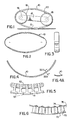
- a track wheel consists of a self supporting longitudinal curved track mounted in an oval geometry on two support rollers.
- the track wheel is in effect an oval wheel with two axles.
- the axles of the two support rollers are mounted to the vehicle.
- the rollers support and guide both ends of the track in the small curvatures and transfer vehicle load at the lower curved part of the track.
- a further object of an embodiment of the invention is the provision of spring suspension which is an integral part of the spring track, in place of separate suspension and/or inflated tires.
- a further object of an embodiment of the invention is the provision of a small mass of the spring track to provide superior suspension for light weight vehicles at higher speed as compared to wheels with tires and conventional spring suspension.
- track wheels will have a much lower rolling resistance, lower weight and less wear due to the elimination of most of the supporting rollers.
- the present invention provides a suspension device,for supporting a load such as a vehicle,in rolling contact with a surface, the suspension means comprising a track which entrains a pair of spaced rollers so that a lower portion of the track intermediate therfollers which is in engagement with the surface defines an arc advantageously of between 15 degrees and 120 degrees and preferably between 20 degrees and 90 degrees when the device is in an unloaded condition.
- This invention further provides a track for mounting on a pair of load bearing rollers, the track having longitudinal curvature limiting means for resisting flattening beyond a predetermined maximum radius under load, but substantially free to bend to a smaller radius of curvature for passage around the rollers
- a track wheel shown generally includes a band or track 10 with curvature limiting means, which entrains a pair of spaced apart rollers 18,20.
- a lower portion 12 of the track 10 intermediate the rollers is adapted to engage a surface and defines an arc of from 15 degrees to 120 degrees. This results in a ground or surface engaging portion having a large footprint of a wheel with diameter many times the height of track while maintaining a curved surface unsupported by bogey wheels or rollers found in conventional tracked vehicle.
- the spring track may be made from a thin spring steel band shown generally in Figure 4 which is curved concave towards the centre, both longitudinally and transversely as detailed below.
- the band forms an oval shaped loop as shown in Figure 2.
- the dual curved band will naturally take on this oval geometry when unloaded and unconfined.
- the unconfined spring track also retains a stable oval geometry when any segment of the track travels through all points of the oval loop.
- the track is a continuous loop of a curved spring band made of spring steel or a fiber reinforced plastic composite, as shown in Figures 2 and 3.
- the track loop has a natural oval geometry with dimensions which are determined by its preformed longitudinal and transverse curvatures.
- the small curvatures of the oval geometry have the same radius as the transverse curvature of the preformed track ribbon; this is similar to the curvature of the bend in a spring steel measuring tape when it is folded lengthwise.
- the large curvatures of the oval shape are formed in the fabricating process. If the spring track is cut anywhere in the loop it will spring open to a longitudinal curved ribbon with the same radius as the large radius of the oval geometry and with an arc of about 63 to 252 degrees, as shown in Figure 4. These angles correspond to the arcs of 15 and 120 degrees for the large radius portions of spring tracks where the small radius is one tenth the size of the large radius.
- Figure 4A shows the cross section of the curved ribbon of Figure 4 and of the spring track of Figures 2 and 3. This cross section if shown with a radial curvature and with uniform thickness. Curvatures other than radial, e.g. hyperbolic or parabolic,and non uniform section thickness may also be used to obtain longitudinal curvature limiting characteristics.
- Materials used for the spring track should have a high flexural fatigue strength and a low hysteresis loss factor. Rolling resistance of the spring track will increase with a higher hysteresis loss factor. This factor is a measure of the power dissipated as heat when the material is flexed or deformed.
- Materials used for springs will be suitable for use on spring tracks. Reinforced plastic containing filaments such,for example, as an aromatic polyamide, e.g., Kevlar (Trade Mark), are also suitable.
- a rubber coating is preferably provided on the outer surface of the track.
- a maximum load for a track may be calculated. For instance, a steel spring track with a track thickness of 1mm, a width of 10cm, and a track length of 60cm between centres of the support rollers will have a theoretical loading capacity of about 100kg.
- Tracks may be mounted on a track wheel frame 15 with bearings for axles 14 and 16 of the two support rollers 18 and 20 shown in Figure 1. This frame is then attached to a vehicle.
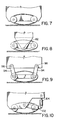
- the track support rollers 18 and 20 may have bearings which fit on the two axles 14 and 16 which are attached directly to a vehicle as shown in Figure 7.
- the spring track of Figure 2 must be installed on the support rollers 18 and 20 in an elongated, prestressed shape.
- the extent of prestressing may vary with the application. More prestressing will result in stiffer suspension and a longer footprint.
- the track should not stretch beyond the rollers. Under vehicle loading, the lower segment of the track will bend to a larger curvature while the top segment will bend back to a smaller curvature; closer to that of the unloaded track.
- a deflection limiting roller may be mounted on the lower part of the track wheel frame 15 between the track support rollers 18 and 20. The track will only engage this deflection limiting roller when vehicle load on the track wheel exceeds the load limits of the track.
- the spring track wheel of Figure 1 can also be compared to a wheel with an inflated tire which is suspended with springs and shock absorbers, as on automobiles.
- the main advantage of a spring track wheel is the relative small mass of the deflected track segment as compared to the mass of a suspended wheel with tire.
- a pivot hinged segment track consists of many segments 51 which are joined by pivot shafts or pins 52 similar to a link chain. A short length of this track is shown generally in Figure 5.
- Each segment 51 has a T-shaped cross section with two pivot holes at the top. The track will curve longitudinally, because the distance between the pivot holes is slightly less than the width of the outer part of a track segment. When the track is resting on the ground it will support a downward load applied by the two support rollers.
- An optional rubber tread part 53 may be bonded to every second track segment. This tread part will cover the gap between the track segments when the track is bent over the support rollers.
- FIG. 6 Another alternative track construction is in the form of band hinged segment track.
- a short length of this track consisting of five segments is shown generally in Figure 6.
- Each segment may consist of a spacer 70 and a compression member 72.
- the compression member 72 and spacer 70 are secured as by rivets 74 or other suitable means to a flexible belt or steel tension member 76.
- the compression member 72 may be interlocking plates to enhance rigidity of the track.
- the average width of the interlocking plate 72 is slightly longer than the distance between the rivet holes in tension member 76 to provide an arc of from 15 degrees to 120 degrees intermediate the rollers 18 and 20 as described with reference to Figure 1.
- Figures 8 and 9 show swiveled mounting arrangements of a track wheel to a vehicle as an alternative to a fixed track wheel mounting shown in Figure 7. This mounting allows the track wheel to swivel when it rolls over uneven terrain or when it encounters obstacles. Length of the swivel arms 94 and locations of swivel points 82, 96, 98 can be selected to provide a tilt up slant to the track wheel in the direction of rolling.
- a semi-fixed mounting arrangement of a track wheel to a vehicle is shown in Figure 10.
- One of the rollers is attached directly to the vehicle and the second roller is mounted on a swivel arm 102 in a manner that it will elongate the track when a load is applied on the wheel.
- Vehicle load is transferred to this second roller by means of a spring and damper 104 which is mounted between vehicle and the swivel arm to provide additional track wheel deflection and suspension.
- a track wheel can be used on vehicles in place of conventional wheels.
- Track wheels can be applied on slow speed vehicles used on farms, construction sites or in open fields; other applications are track wheels for wheelbarrows, snowblowers, lawnmowers, wheelchairs and lawnchairs.
- Track wheels are also used advantageously on faster moving vehicles such as snowmobiles and in place of aircraft landing wheels.
Landscapes
- Engineering & Computer Science (AREA)
- Chemical & Material Sciences (AREA)
- Combustion & Propulsion (AREA)
- Transportation (AREA)
- Mechanical Engineering (AREA)
- Vehicle Body Suspensions (AREA)
- Handcart (AREA)
Applications Claiming Priority (2)
| Application Number | Priority Date | Filing Date | Title |
|---|---|---|---|
| CA566076 | 1988-05-05 | ||
| CA000566076A CA1326256C (en) | 1988-05-05 | 1988-05-05 | Track wheel |
Publications (2)
| Publication Number | Publication Date |
|---|---|
| EP0341083A2 true EP0341083A2 (de) | 1989-11-08 |
| EP0341083A3 EP0341083A3 (de) | 1991-03-20 |
Family
ID=4137976
Family Applications (1)
| Application Number | Title | Priority Date | Filing Date |
|---|---|---|---|
| EP19890304577 Withdrawn EP0341083A3 (de) | 1988-05-05 | 1989-05-05 | Raupenrad |
Country Status (3)
| Country | Link |
|---|---|
| US (1) | US4957332A (de) |
| EP (1) | EP0341083A3 (de) |
| CA (1) | CA1326256C (de) |
Cited By (1)
| Publication number | Priority date | Publication date | Assignee | Title |
|---|---|---|---|---|
| EP0474405A1 (de) * | 1990-08-22 | 1992-03-11 | Jan Hendrik Barnard | Fahrzeugantrieb |
Families Citing this family (9)
| Publication number | Priority date | Publication date | Assignee | Title |
|---|---|---|---|---|
| GB8916533D0 (en) * | 1989-07-19 | 1989-09-06 | Sauve Bernard | Endless chain system for bicycles and motorcycles |
| US5427443A (en) * | 1992-11-27 | 1995-06-27 | Bridgestone Corporation | Annular elastic track |
| CA2115697A1 (en) * | 1994-02-15 | 1995-08-16 | Joost Batelaan | Short track wheel |
| USD389100S (en) | 1996-07-09 | 1998-01-13 | Jim Szymanski | Tread for walker |
| US6516848B1 (en) | 1999-05-18 | 2003-02-11 | Anthony Italo Provitola | Toroidal wheel |
| US6421528B1 (en) * | 1999-04-29 | 2002-07-16 | Hughes Electronics Corp. | Satellite transmission system with adaptive transmission loss compensation |
| US7641006B2 (en) * | 2002-06-27 | 2010-01-05 | Scheetz Inc. | Military vehicle with electric drive running gear system |
| US7644788B2 (en) * | 2002-06-27 | 2010-01-12 | Scheetz Inc. | Tensioning and suspension system for a trailer |
| US6860571B2 (en) * | 2002-06-27 | 2005-03-01 | Scheetz Technology, Inc. | Suspension system, positive hydraulic braking system, positive drive belt system and belt tensioning device for wheel and belt driven devices |
Family Cites Families (10)
| Publication number | Priority date | Publication date | Assignee | Title |
|---|---|---|---|---|
| DE68894C (de) * | J. ROTTKAMP in Köln, Rhein, Ehrenstr. 45^1 | Um die Räder eines Wagens gelegtes Stahlband zur leichteren Ueberwindung der Unebenheiten der Fahrbahn und zur Verringerung der Stöfse | ||
| US905405A (en) * | 1908-06-18 | 1908-12-01 | Willis N Britton | Traction-wheel and runner for vehicles. |
| FR565512A (fr) * | 1923-04-25 | 1924-01-29 | Perfectionnements aux propulseurs | |
| GB271861A (en) * | 1926-05-25 | 1928-03-08 | Le Telesco | Improvements in resilient or spring wheels |
| US2055932A (en) * | 1933-01-21 | 1936-09-29 | Kitchen John George Aulsebrook | Endless traveler band, track and the like |
| US2806291A (en) * | 1955-09-19 | 1957-09-17 | Kenneth E Robertson | Land measuring wheel |
| FR1443364A (fr) * | 1965-05-13 | 1966-06-24 | Bande élastique de roulement sans axes ni rayons destinée à remplacer les roues d'un véhicule | |
| DE1480857A1 (de) * | 1966-03-18 | 1969-05-22 | Ifa Getriebewerke Brandenburg | Endloses Gleisband,insbesondere fuer Raupenfahrzeuge |
| US4386809A (en) * | 1981-03-16 | 1983-06-07 | The United States Of America As Represented By The Secretary Of The Army | Driving-guidance system for a resilient vehicle propulsion band |
| US4752105A (en) * | 1985-10-24 | 1988-06-21 | Barnard Jan H | Vehicle traction |
-
1988
- 1988-05-05 CA CA000566076A patent/CA1326256C/en not_active Expired - Fee Related
-
1989
- 1989-05-04 US US07/347,008 patent/US4957332A/en not_active Expired - Fee Related
- 1989-05-05 EP EP19890304577 patent/EP0341083A3/de not_active Withdrawn
Cited By (1)
| Publication number | Priority date | Publication date | Assignee | Title |
|---|---|---|---|---|
| EP0474405A1 (de) * | 1990-08-22 | 1992-03-11 | Jan Hendrik Barnard | Fahrzeugantrieb |
Also Published As
| Publication number | Publication date |
|---|---|
| CA1326256C (en) | 1994-01-18 |
| US4957332A (en) | 1990-09-18 |
| EP0341083A3 (de) | 1991-03-20 |
Similar Documents
| Publication | Publication Date | Title |
|---|---|---|
| KR101059722B1 (ko) | 컴플라이언트 휠 | |
| US4779894A (en) | Vehicle suspension | |
| CN105636799B (zh) | 具有减小的横向硬度的非充气式车轮 | |
| CA1326256C (en) | Track wheel | |
| US6547340B2 (en) | Low vibration omni-directional wheel | |
| EP0245307B1 (de) | Den grund berührende fläche für raupen, räder und reifen | |
| US20050127752A1 (en) | Adaptable traction system of a vehicle | |
| AU2002334364A1 (en) | Adaptable traction system of a vehicle | |
| JPH11514602A (ja) | 車両用の非空圧式タイヤ、およびキャタピラー履板 | |
| KR20010031541A (ko) | 운송 기구 | |
| CN108698652B (zh) | 用于车辆的履带 | |
| US11352078B2 (en) | Track system for a vehicle | |
| US5228528A (en) | Track for tracked motorcycle | |
| US4801019A (en) | Shock absorbing unit assisted by fiberglass reinforced spring | |
| US5427443A (en) | Annular elastic track | |
| US20060046826A1 (en) | Automobile racing suspension system | |
| GB2109752A (en) | Wheel assemblies for vehicles | |
| US5678903A (en) | Short track wheel | |
| EP0960748A2 (de) | Dauerhaftes komfortabeles Rad und Vollreifen | |
| CA1082234A (en) | Sprung vehicles | |
| AU7612601A (en) | A dual tracked drive unit for a self-propelled irrigation system | |
| AU586902B2 (en) | Ground engaging surface for endless tracks, wheels and tyres | |
| RU2043203C1 (ru) | Колесо транспортного средства | |
| Batelaan | Track wheel-a hybrid vehicle suspension system | |
| US2661251A (en) | Track device for vehicles and the like |
Legal Events
| Date | Code | Title | Description |
|---|---|---|---|
| PUAI | Public reference made under article 153(3) epc to a published international application that has entered the european phase |
Free format text: ORIGINAL CODE: 0009012 |
|
| AK | Designated contracting states |
Kind code of ref document: A2 Designated state(s): DE FR GB |
|
| PUAL | Search report despatched |
Free format text: ORIGINAL CODE: 0009013 |
|
| AK | Designated contracting states |
Kind code of ref document: A3 Designated state(s): DE FR GB |
|
| 17P | Request for examination filed |
Effective date: 19910902 |
|
| 17Q | First examination report despatched |
Effective date: 19920430 |
|
| RAP1 | Party data changed (applicant data changed or rights of an application transferred) |
Owner name: BATELAAN, JOOST |
|
| STAA | Information on the status of an ep patent application or granted ep patent |
Free format text: STATUS: THE APPLICATION IS DEEMED TO BE WITHDRAWN |
|
| 18D | Application deemed to be withdrawn |
Effective date: 19930703 |