EP0340738A2 - Vehicle suspension system - Google Patents
Vehicle suspension system Download PDFInfo
- Publication number
- EP0340738A2 EP0340738A2 EP89107952A EP89107952A EP0340738A2 EP 0340738 A2 EP0340738 A2 EP 0340738A2 EP 89107952 A EP89107952 A EP 89107952A EP 89107952 A EP89107952 A EP 89107952A EP 0340738 A2 EP0340738 A2 EP 0340738A2
- Authority
- EP
- European Patent Office
- Prior art keywords
- tubular member
- suspension system
- arm
- coil spring
- outer tubular
- Prior art date
- Legal status (The legal status is an assumption and is not a legal conclusion. Google has not performed a legal analysis and makes no representation as to the accuracy of the status listed.)
- Granted
Links
- 239000000725 suspension Substances 0.000 title claims abstract description 63
- 239000000428 dust Substances 0.000 claims description 4
- 230000002093 peripheral effect Effects 0.000 description 5
- 238000006073 displacement reaction Methods 0.000 description 4
- PYVHTIWHNXTVPF-UHFFFAOYSA-N F.F.F.F.C=C Chemical compound F.F.F.F.C=C PYVHTIWHNXTVPF-UHFFFAOYSA-N 0.000 description 1
- 239000011347 resin Substances 0.000 description 1
- 229920005989 resin Polymers 0.000 description 1
Images


Classifications
-
- B—PERFORMING OPERATIONS; TRANSPORTING
- B60—VEHICLES IN GENERAL
- B60G—VEHICLE SUSPENSION ARRANGEMENTS
- B60G99/00—Subject matter not provided for in other groups of this subclass
-
- B—PERFORMING OPERATIONS; TRANSPORTING
- B60—VEHICLES IN GENERAL
- B60G—VEHICLE SUSPENSION ARRANGEMENTS
- B60G7/00—Pivoted suspension arms; Accessories thereof
- B60G7/02—Attaching arms to sprung part of vehicle
-
- B—PERFORMING OPERATIONS; TRANSPORTING
- B60—VEHICLES IN GENERAL
- B60G—VEHICLE SUSPENSION ARRANGEMENTS
- B60G2200/00—Indexing codes relating to suspension types
- B60G2200/10—Independent suspensions
- B60G2200/14—Independent suspensions with lateral arms
- B60G2200/144—Independent suspensions with lateral arms with two lateral arms forming a parallelogram
-
- B—PERFORMING OPERATIONS; TRANSPORTING
- B60—VEHICLES IN GENERAL
- B60G—VEHICLE SUSPENSION ARRANGEMENTS
- B60G2204/00—Indexing codes related to suspensions per se or to auxiliary parts
- B60G2204/10—Mounting of suspension elements
- B60G2204/15—Mounting of subframes
-
- B—PERFORMING OPERATIONS; TRANSPORTING
- B60—VEHICLES IN GENERAL
- B60G—VEHICLE SUSPENSION ARRANGEMENTS
- B60G2204/00—Indexing codes related to suspensions per se or to auxiliary parts
- B60G2204/40—Auxiliary suspension parts; Adjustment of suspensions
- B60G2204/41—Elastic mounts, e.g. bushings
Definitions
- This invention relates to a vehicle suspension system.
- a vehicle suspension system which has a suspension arm the inner end portion of which is bifurcated and comprises a front branch arm and a rear branch arm, and in which the inner ends of the branch arms are supported on the chassis so that the suspension arm can be displaced in the longitudinal direction of the vehicle body.
- the forward displacement of each branch arm is limited by a rubber bushing and forward load acting on the inner end of the suspension arm when the brake is applied is resiliently absorbed by the rubber bushing.
- the primary object of the present invention is to provide a vehicle suspension system which can resiliently absorb the rearward load acting on the inner end of the suspension arm when the vehicle passes a gap, thereby improving the driving comfort.
- a vehicle suspension system comprising a suspension arm having an outer end portion which is connected to a wheel support for rotatably supporting a wheel and an inner end portion which is bifurcated and comprises first and second branch arms spaced from each other in the longitudinal direction of the vehicle body, a pair of slide members which respectively support the inner end portions of the first and second branch arms so that the inner end portions are slidable relative to the vehicle body in the longitudinal direction of the same, a coil spring which is provided for at least one of the first and second branch arms and urges forward the suspension arm, and a stopper means which defines the foremost position of the suspension arm which is urged forward by said coil spring.
- a front cross member 1 extends in the transverse direction of the vehicle body and is connected to a chassis 4 at a portion deviated from the longitudinal axis of the chassis 4.
- a first bracket 2 which is like a hook in cross-section and has an outer side portion extending in the longitudinal direction of the vehicle body.
- a second bracket 3 which conforms to the first bracket 2 in shape as viewed from above is welded to the lower surface of the first bracket 2.
- First and second through holes 5 and 6 extend through the first and second brackets 2 and 3 at front and rear end portions thereof.
- the first and second brackets 2 and 3 are resiliently mounted on the chassis 4 by bolts (not shown) which are inserted into the holes 5 and 6 and tightened on the chassis 4 with an elastic member (not shown) interposed between each bolt and the chassis 4.
- a suspension support member 8 is welded to the first and second brackets 2 and 3 at substantially the middle between the first and second through holes 5 and 6.
- the suspension support member 8 is substantially channel-shaped in cross-section and has an upstanding extension 7 which projects upward.
- a lower arm 10 is bifurcated at the inner end portion thereof. That is, the inner end portion of the lower arm 10 comprises a first branch arm 11 and a second branch arm 14.
- Elongated first-branch-arm mounting holes 9a and 9b are formed in the front and rear walls of the suspension support member 8 at the lower end portion thereof.
- the inner end portion of the first branch arm 11 is mounted between the first-branch-arm mounting holes 9a and 9b by way of a first rubber bushing 12.
- the first rubber bushing 12 comprises an outer tubular member 12a, an inner tubular member 12b received in the outer tubular member 12a, and an elastic member 12c interposed between the outer and inner tubular members 12a and 12b.
- the inner end portion of the first branch arm 11 is welded to the outer tubular member 12a of the first rubber bushing 12, and the first rubber bushing 12 is rotatably mounted between the first-branch-arm mounting holes 9a and 9b by a bolt 13 which is inserted into the first-branch-arm mounting holes 9a and 9b and the inner tubular member 12b.
- the inner end portion of the second branch arm 14 is mounted, by way of a second rubber bushing 16, on a second-branch-arm supporting portion 15 which is formed on the front end portion of the first and second brackets 2 and 3.
- the second rubber bushing 16 comprises an outer tubular member 16a, an inner tubular member 16b and an elastic member 16c interposed therebetween.
- the outer tubular member 16a of the second rubber bushing 16 comprises an outer tubular member 16a, an inner tubular member 16b is fixed to the second-branch-arm supporting portion 15 by a securing bracket 17.
- the inner end of the second branch arm 14 is provided with a bolt member 18 and the bolt member 18 is inserted into the inner tubular member 16b and secured thereto by a nut, whereby the inner end portion of the second branch arm 14 is resiliently connected for rotation to the second-branch-arm supporting portion 15.
- a third bracket 20 which conforms to the upper surface of the suspension support member 8 in shape and reinforces the suspension support member 8.
- a third rubber bushing 21 and a fourth rubber bushing 22 are spaced from each other in the longitudinal direction of the vehicle body and mounted on the upper ends of the suspension support member 8 and the third bracket 20.
- the third rubber bushing 21 comprises an outer tubular member 21a, an inner tubular member 21b which is longer than the outer tubular member 21a, and an elastic member 21c which is interposed between the outer and inner tubular members 21a and 21b and urges the inner tubular member 21b to project upward.
- the outer peripheral surface of the outer tubular member 21a is welded to the upper ends of the suspension support member 8 and the third bracket 20.
- the inner tubular member 21b is provided on its inner peripheral surface with a thread 24.
- a bolt 23 is screwed into the inner tubular member 21b so that the upper surface of the inner tubular member 21b is pressed against a mounting surface 4a of the chassis 4 from below under the resiliency of the elastic member 21c.
- the fourth rubber bushing 22 is the same as the third rubber bushing 21 and is mounted on the chassis 4 in the same manner. The suspension support member 8 and the third bracket 20 are thus resiliently mounted on the chassis 4 by way of the third and fourth rubber bushings 21 and 22.
- a upper arm 32 is bifurcated at the inner end portion thereof. That is, the inner end portion of the upper arm 32 comprises an upper first branch arm 33 and an upper second branch arm 35.
- An upper-first-branch-arm mounting hole 30 and an upper-second-branch-arm mounting hole 31 are respectively formed in the front and rear walls of the upstanding extension 7 of the suspension support member 8 and are in alignment with each other.
- the inner end portion of the upper first branch arm 33 is mounted on the upstanding extension 7 by way of a fifth rubber bushing 34 at the upper-first-branch-arm mounting hole 30, and the inner end portion of the upper second branch arm 35 is mounted on the upstanding extension 7 by way of a sixth rubber bushing 36 at the upper-second-branch-arm mounting hole 31.
- the fifth rubber bushing 34 includes an outer tubular member 34a fixed to the inner end portion of the upper first branch arm 33, and an inner tubular member 34b which is longer than the outer tubular member 34a.
- a tubular support member 37 is loosely fitted on the inner tubular member 34b to be slidable in the longitudinal direction relative to the inner tubular member 34b and to be rotatable about the same.
- An elastic member 34c is fixed to the inner peripheral surface of the outer tubular member 34a and the outer peripheral surface of the tubular support member 37.
- a first spring retainer 39 rests on one end of the outer tubular member 34a to be rotatable about the inner tubular member 34b with a rotatable member 38 intervening between the first spring retainer 39 and the outer tubular member 34a.
- the first spring retainer 39 is fitted on the inner tubular member 34b at an intermediate portion thereof to be rotatable and slidable in the longitudinal direction of the inner tubular member 34b.
- a second spring retainer 40 which is like a disk in shape is fixed to the rear end of the inner tubular member 34b so as to oppose to the first spring retainer 39.
- the first spring retainer 39 is cranked in cross-section and has outer and inner shoulders, the outer shoulder being near to the second spring retainer 40 than the inner shoulder.
- An annular rubber stopper 41 which is rectangular in cross-section is fixed to the outer shoulder of the first spring retainer 39 in alignment with the outer portion of the second spring retainer 40.
- a first coil spring 42 is compressed between the inner shoulder of the first spring retainer 39 and the inner portion of the second spring retainer 40 and urges forward the upper first branch arm 33 (the upper arm 32) by way of the first spring retainer 39, the rotatable member 38 and the outer tubular member 34a of the fifth rubber bushing 34.
- the first coil spring has a spring constant of K1.
- a stopper 34d is fixed to the front end portion of the inner tubular member 34b and is adapted to abut against the front end face of the elastic member 34c, thereby limiting the foremost position of the outer tubular member 34a, i.e., the foremost position of the upper arm 32.
- a rubber dust boot member 43 is fixed to the rear end of the first spring retainer 39 at the outer edge thereof and to the rear end portion of the inner tubular member 34b behind the second spring retainer 40 at the inner edge thereof.
- the inner peripheral surface of the tubular support member 37 in contact with the outer surface of the inner tubular member 34b and the surface of the first spring retainer 39 in contact with the rotatable member 38 are treated with ethylene tetrafluoride resin so that they can smoothly slide or rotate relative to the surfaces in contact with them.
- the rubber stopper 41 resiliently limits a rearward movement of the first spring retainer 39 which is made overcoming the force of the first coil spring 42.
- the sixth rubber bushing 36 is substantially the same as the fifth rubber bushing 34 though it is directed in the direction reverse to the fifth rubber bushing 34. That is, the sixth rubber bushing 36 comprises an outer tubular member 36a fixed to the inner end portion of the upper second branch arm 35, an inner tubular member 36b, an elastic member 36c, a tubular support member 37, a rotatable member 38, a first spring retainer 39, a second spring retainer 40, a rubber stopper 41, a rubber dust boot member 43, a stopper 36d and a second coil spring 44.
- the spring constant K2 of the second coil spring 44 which is equivalent to the first coil spring 42 in the fifth rubber bushing 34 is smaller than the spring constant K1 of the first coil spring 42.
- the second coil spring 44 urges rearward the upper second branch arm 35.
- the stopper 36d limits the rear most position of the outer tubular member 36a.
- the fifth and sixth rubber bushings 34 and 36 are connected to the upstanding extension 7 of the suspension support member 8 by means of a long bolt member 45 which is inserted into the inner tubular members 34b and 36b, the upper-first-branch-arm mounting hole 30 and the upper-second-branch-arm mounting hole 31 with the fifth and sixth rubber bushings 34 and 36 being positioned on opposite sides of the upstanding extension 7.
- the inner end portions of the upper first branch arm 33 and the upper second branch arm 35 are resiliently and rotatably mounted on the upstanding extension 7 of the suspension support member 8 by way of the fifth and sixth rubber bushings 34 and 36.
- the second coil spring 44 is compressed in the sixth rubber bushing 36 with the rubber stopper 41 being in abutment against the second spring retainer 40 and the inner tubular member 36b of the sixth rubber bushing 36 being displaced rearward as shown in Figure 4 since the spring constant K2 of the second coil spring 44 is smaller than that of the first coil spring 42.
- the upper branch arms 33 and 35 and the lower branch arms 11 and 14 are mounted on the front cross member 1 before the front cross member 1 is mounted on the chassis 4.
- the outer ends of the lower arm 10 and the upper arm 32 are connected to a wheel support 47 for supporting a wheel 46.
- the upper arm 32 is urged forward by the first spring 42 disposed in the fifth rubber bushing 34 and rearward by the second spring 44 disposed in the sixth rubber bushing 36.
- This arrangement is advantageous in that each rubber bushing may be smaller in size when a given spring constant which acts against the rearward displacement of the upper arm 32 is obtained by two coil springs than when the given spring constant is obtained by a single coil spring.
- the first and second coil springs 42 and 44 are both arranged to urge forward the upper arm 32 unlike in the embodiment described above, the second coil spring 44 must be positioned on the outer side of the upper second branch arm 35, which is not preferable from the viewpoint of compactly arranging the suspension arm supporting portion.
- the coil springs are positioned on the inner side of the upper first branch arm 33 and the upper second branch arm 35, i.e., between the branch arms 33 and 35, and are directed so that they urge the upper arm 32 in opposite directions, and the spring constant of the spring urging forward the upper arm 32 is set to be larger than that of the coil spring urging rearward the upper arm 32 as in the embodiment described above, the upper arm is normally positioned in the foremost position, and the sum of the springs constants K1 and K2 act against rearward displacement of the upper arm 32 from the foremost position.
- the upper arm 32 can be displaced rearward and the lower arm 10 cannot be displaced rearward. That is, the driving comfort during passage of a gap can be improved when one of the upper arm and the lower arm is arranged so that it can be displaced rearward.
- the lower arm 10 can be displaced rearward, the lower arm 10 is displaced rearward when the brake is applied, which causes braking judder.
- forward load acts on the upper arm when the brake is applied, and accordingly, when the upper arm 32 is supported so that it can be displaced rearward and only rearward while the lower arm 10 is supported so that it cannot be displaced rearward, the driving comfort can be improved and at the same time, the braking judder can be suppressed.
Abstract
Description
- This invention relates to a vehicle suspension system.
- As disclosed, for instance, in Japanese Utility Model Publication No. 62(1987)-11203, there has been known a vehicle suspension system which has a suspension arm the inner end portion of which is bifurcated and comprises a front branch arm and a rear branch arm, and in which the inner ends of the branch arms are supported on the chassis so that the suspension arm can be displaced in the longitudinal direction of the vehicle body. The forward displacement of each branch arm is limited by a rubber bushing and forward load acting on the inner end of the suspension arm when the brake is applied is resiliently absorbed by the rubber bushing.
- When a vehicle passes a gap, rearward load acts on the inner end of the suspension arm. In order to improve the driving comfort, it is preferred that the rearward load be resiliently absorbed. However, it is difficult to absorb the rearward load by a rubber bushing since the rubber bushing is hard to set to have a predetermined spring constant and the spring constant of the rubber bushing is apt to change with age. Further, it is difficult to ensure a sufficient displacement of the inner end of the suspension arm with the rubber bushing.
- In view of the foregoing observations and description, the primary object of the present invention is to provide a vehicle suspension system which can resiliently absorb the rearward load acting on the inner end of the suspension arm when the vehicle passes a gap, thereby improving the driving comfort.
- In accordance with the present invention, there is provided a vehicle suspension system comprising a suspension arm having an outer end portion which is connected to a wheel support for rotatably supporting a wheel and an inner end portion which is bifurcated and comprises first and second branch arms spaced from each other in the longitudinal direction of the vehicle body, a pair of slide members which respectively support the inner end portions of the first and second branch arms so that the inner end portions are slidable relative to the vehicle body in the longitudinal direction of the same, a coil spring which is provided for at least one of the first and second branch arms and urges forward the suspension arm, and a stopper means which defines the foremost position of the suspension arm which is urged forward by said coil spring.
-
- Figure 1 is a front view showing a vehicle suspension system in accordance with an embodiment of the present invention,
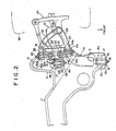
- Figure 2 is a plan view of the vehicle suspension system,
- Figure 3 is a plan view of the upper arm with rubber bushings on the inner ends of the upper first branch arm and the upper second branch arm, and
- Figure 4 is a plan view similar to Figure 3 but showing the state after the upper arm is mounted on the chassis.
- In Figures 1 and 2, a front cross member 1 extends in the transverse direction of the vehicle body and is connected to a
chassis 4 at a portion deviated from the longitudinal axis of thechassis 4. To one side end of the front cross member 1 is welded afirst bracket 2 which is like a hook in cross-section and has an outer side portion extending in the longitudinal direction of the vehicle body. Asecond bracket 3 which conforms to thefirst bracket 2 in shape as viewed from above is welded to the lower surface of thefirst bracket 2. First and second throughholes second brackets second brackets chassis 4 by bolts (not shown) which are inserted into theholes chassis 4 with an elastic member (not shown) interposed between each bolt and thechassis 4. - A
suspension support member 8 is welded to the first andsecond brackets holes suspension support member 8 is substantially channel-shaped in cross-section and has an upstanding extension 7 which projects upward. Alower arm 10 is bifurcated at the inner end portion thereof. That is, the inner end portion of thelower arm 10 comprises a first branch arm 11 and asecond branch arm 14. Elongated first-branch-arm mounting holes suspension support member 8 at the lower end portion thereof. The inner end portion of the first branch arm 11 is mounted between the first-branch-arm mounting holes first rubber bushing 12 comprises an outer tubular member 12a, an inner tubular member 12b received in the outer tubular member 12a, and anelastic member 12c interposed between the outer and inner tubular members 12a and 12b. The inner end portion of the first branch arm 11 is welded to the outer tubular member 12a of thefirst rubber bushing 12, and thefirst rubber bushing 12 is rotatably mounted between the first-branch-arm mounting holes arm mounting holes second branch arm 14 is mounted, by way of a second rubber bushing 16, on a second-branch-arm supporting portion 15 which is formed on the front end portion of the first andsecond brackets second rubber bushing 16 comprises an outer tubular member 16a, an innertubular member 16b and anelastic member 16c interposed therebetween. The outer tubular member 16a of thesecond rubber bushing 16 comprises an outer tubular member 16a, an innertubular member 16b is fixed to the second-branch-arm supporting portion 15 by a securingbracket 17. The inner end of thesecond branch arm 14 is provided with abolt member 18 and thebolt member 18 is inserted into the innertubular member 16b and secured thereto by a nut, whereby the inner end portion of thesecond branch arm 14 is resiliently connected for rotation to the second-branch-arm supporting portion 15. - To the upper end portion of the
suspension support member 8 is welded athird bracket 20 which conforms to the upper surface of thesuspension support member 8 in shape and reinforces thesuspension support member 8. A third rubber bushing 21 and a fourth rubber bushing 22 are spaced from each other in the longitudinal direction of the vehicle body and mounted on the upper ends of thesuspension support member 8 and thethird bracket 20. Thethird rubber bushing 21 comprises an outertubular member 21a, an inner tubular member 21b which is longer than the outertubular member 21a, and an elastic member 21c which is interposed between the outer and innertubular members 21a and 21b and urges the inner tubular member 21b to project upward. The outer peripheral surface of the outertubular member 21a is welded to the upper ends of thesuspension support member 8 and thethird bracket 20. The inner tubular member 21b is provided on its inner peripheral surface with athread 24. Abolt 23 is screwed into the inner tubular member 21b so that the upper surface of the inner tubular member 21b is pressed against amounting surface 4a of thechassis 4 from below under the resiliency of the elastic member 21c. The fourth rubber bushing 22 is the same as the third rubber bushing 21 and is mounted on thechassis 4 in the same manner. Thesuspension support member 8 and thethird bracket 20 are thus resiliently mounted on thechassis 4 by way of the third andfourth rubber bushings 21 and 22. - A
upper arm 32 is bifurcated at the inner end portion thereof. That is, the inner end portion of theupper arm 32 comprises an upperfirst branch arm 33 and an uppersecond branch arm 35. An upper-first-branch-arm mounting hole 30 and an upper-second-branch-arm mounting hole 31 are respectively formed in the front and rear walls of the upstanding extension 7 of thesuspension support member 8 and are in alignment with each other. The inner end portion of the upperfirst branch arm 33 is mounted on the upstanding extension 7 by way of a fifth rubber bushing 34 at the upper-first-branch-arm mounting hole 30, and the inner end portion of the uppersecond branch arm 35 is mounted on the upstanding extension 7 by way of a sixth rubber bushing 36 at the upper-second-branch-arm mounting hole 31. As shown in Figure 3, thefifth rubber bushing 34 includes an outertubular member 34a fixed to the inner end portion of the upperfirst branch arm 33, and an innertubular member 34b which is longer than the outertubular member 34a. Atubular support member 37 is loosely fitted on the innertubular member 34b to be slidable in the longitudinal direction relative to the innertubular member 34b and to be rotatable about the same. Anelastic member 34c is fixed to the inner peripheral surface of the outertubular member 34a and the outer peripheral surface of thetubular support member 37. Afirst spring retainer 39 rests on one end of the outertubular member 34a to be rotatable about the innertubular member 34b with arotatable member 38 intervening between thefirst spring retainer 39 and the outertubular member 34a. Thefirst spring retainer 39 is fitted on the innertubular member 34b at an intermediate portion thereof to be rotatable and slidable in the longitudinal direction of the innertubular member 34b. Asecond spring retainer 40 which is like a disk in shape is fixed to the rear end of the innertubular member 34b so as to oppose to thefirst spring retainer 39. Thefirst spring retainer 39 is cranked in cross-section and has outer and inner shoulders, the outer shoulder being near to thesecond spring retainer 40 than the inner shoulder. Anannular rubber stopper 41 which is rectangular in cross-section is fixed to the outer shoulder of thefirst spring retainer 39 in alignment with the outer portion of thesecond spring retainer 40. Afirst coil spring 42 is compressed between the inner shoulder of thefirst spring retainer 39 and the inner portion of thesecond spring retainer 40 and urges forward the upper first branch arm 33 (the upper arm 32) by way of thefirst spring retainer 39, therotatable member 38 and the outertubular member 34a of the fifth rubber bushing 34. The first coil spring has a spring constant of K1. Astopper 34d is fixed to the front end portion of the innertubular member 34b and is adapted to abut against the front end face of theelastic member 34c, thereby limiting the foremost position of the outertubular member 34a, i.e., the foremost position of theupper arm 32. A rubberdust boot member 43 is fixed to the rear end of thefirst spring retainer 39 at the outer edge thereof and to the rear end portion of the innertubular member 34b behind thesecond spring retainer 40 at the inner edge thereof. The inner peripheral surface of thetubular support member 37 in contact with the outer surface of the innertubular member 34b and the surface of thefirst spring retainer 39 in contact with therotatable member 38 are treated with ethylene tetrafluoride resin so that they can smoothly slide or rotate relative to the surfaces in contact with them. Therubber stopper 41 resiliently limits a rearward movement of thefirst spring retainer 39 which is made overcoming the force of thefirst coil spring 42. - The
sixth rubber bushing 36 is substantially the same as the fifth rubber bushing 34 though it is directed in the direction reverse to thefifth rubber bushing 34. That is, thesixth rubber bushing 36 comprises an outertubular member 36a fixed to the inner end portion of the uppersecond branch arm 35, an innertubular member 36b, anelastic member 36c, atubular support member 37, arotatable member 38, afirst spring retainer 39, asecond spring retainer 40, arubber stopper 41, a rubberdust boot member 43, astopper 36d and asecond coil spring 44. The spring constant K2 of thesecond coil spring 44 which is equivalent to thefirst coil spring 42 in thefifth rubber bushing 34 is smaller than the spring constant K1 of thefirst coil spring 42. Thesecond coil spring 44 urges rearward the uppersecond branch arm 35. Thestopper 36d limits the rear most position of the outertubular member 36a. The fifth andsixth rubber bushings suspension support member 8 by means of along bolt member 45 which is inserted into the innertubular members arm mounting hole 30 and the upper-second-branch-arm mounting hole 31 with the fifth andsixth rubber bushings first branch arm 33 and the uppersecond branch arm 35 are resiliently and rotatably mounted on the upstanding extension 7 of thesuspension support member 8 by way of the fifth andsixth rubber bushings second coil spring 44 is compressed in thesixth rubber bushing 36 with therubber stopper 41 being in abutment against thesecond spring retainer 40 and the innertubular member 36b of thesixth rubber bushing 36 being displaced rearward as shown in Figure 4 since the spring constant K2 of thesecond coil spring 44 is smaller than that of thefirst coil spring 42. Theupper branch arms lower branch arms 11 and 14 are mounted on the front cross member 1 before the front cross member 1 is mounted on thechassis 4. The outer ends of thelower arm 10 and theupper arm 32 are connected to awheel support 47 for supporting awheel 46. - For example, when the vehicle passes a gap, rearward load acts on the fifth and
sixth rubber bushings upper arm 32 from thewheel 46, and theupper arm 32 is displaced rearward overcoming the sum of the spring forces of the first and second coil springs 42 and 44, whereby thewheel 46 momentarily escapes rearward and the driving comfort during passage of gaps is improved. - As can be understood from the description above, in the suspension system of this embodiment, the
upper arm 32 is urged forward by thefirst spring 42 disposed in thefifth rubber bushing 34 and rearward by thesecond spring 44 disposed in thesixth rubber bushing 36. This arrangement is advantageous in that each rubber bushing may be smaller in size when a given spring constant which acts against the rearward displacement of theupper arm 32 is obtained by two coil springs than when the given spring constant is obtained by a single coil spring. Further, if the first and second coil springs 42 and 44 are both arranged to urge forward theupper arm 32 unlike in the embodiment described above, thesecond coil spring 44 must be positioned on the outer side of the uppersecond branch arm 35, which is not preferable from the viewpoint of compactly arranging the suspension arm supporting portion. On the other hand, when the coil springs are positioned on the inner side of the upperfirst branch arm 33 and the uppersecond branch arm 35, i.e., between thebranch arms upper arm 32 in opposite directions, and the spring constant of the spring urging forward theupper arm 32 is set to be larger than that of the coil spring urging rearward theupper arm 32 as in the embodiment described above, the upper arm is normally positioned in the foremost position, and the sum of the springs constants K1 and K2 act against rearward displacement of theupper arm 32 from the foremost position. - Further, in the embodiment described above, the
upper arm 32 can be displaced rearward and thelower arm 10 cannot be displaced rearward. That is, the driving comfort during passage of a gap can be improved when one of the upper arm and the lower arm is arranged so that it can be displaced rearward. However, if thelower arm 10 can be displaced rearward, thelower arm 10 is displaced rearward when the brake is applied, which causes braking judder. On the other hand, forward load acts on the upper arm when the brake is applied, and accordingly, when theupper arm 32 is supported so that it can be displaced rearward and only rearward while thelower arm 10 is supported so that it cannot be displaced rearward, the driving comfort can be improved and at the same time, the braking judder can be suppressed.
Claims (20)
Applications Claiming Priority (2)
| Application Number | Priority Date | Filing Date | Title |
|---|---|---|---|
| JP63108765A JPH0712768B2 (en) | 1988-04-30 | 1988-04-30 | Vehicle suspension system |
| JP108765/88 | 1988-04-30 |
Publications (3)
| Publication Number | Publication Date |
|---|---|
| EP0340738A2 true EP0340738A2 (en) | 1989-11-08 |
| EP0340738A3 EP0340738A3 (en) | 1990-01-17 |
| EP0340738B1 EP0340738B1 (en) | 1993-03-10 |
Family
ID=14492923
Family Applications (1)
| Application Number | Title | Priority Date | Filing Date |
|---|---|---|---|
| EP89107952A Expired - Lifetime EP0340738B1 (en) | 1988-04-30 | 1989-05-02 | Vehicle suspension system |
Country Status (4)
| Country | Link |
|---|---|
| US (1) | US5009448A (en) |
| EP (1) | EP0340738B1 (en) |
| JP (1) | JPH0712768B2 (en) |
| DE (1) | DE68905223T2 (en) |
Cited By (1)
| Publication number | Priority date | Publication date | Assignee | Title |
|---|---|---|---|---|
| US7273220B2 (en) | 2005-02-22 | 2007-09-25 | Daimlerchrysler Ag | Wheel suspension |
Families Citing this family (5)
| Publication number | Priority date | Publication date | Assignee | Title |
|---|---|---|---|---|
| US5338057A (en) * | 1992-11-12 | 1994-08-16 | Mascotech, Inc. | Upper control arm for vehicle suspension |
| JP4025410B2 (en) * | 1998-02-19 | 2007-12-19 | 東海ゴム工業株式会社 | Anti-vibration device manufacturing method |
| US6901422B1 (en) | 2001-03-21 | 2005-05-31 | Apple Computer, Inc. | Matrix multiplication in a vector processing system |
| IL145245A0 (en) * | 2001-09-03 | 2002-06-30 | Jtc 2000 Dev Delaware Inc | System and method including vector-matrix multiplication |
| US9102205B2 (en) * | 2011-02-01 | 2015-08-11 | Polaris Industries Inc. | All terrain vehicle |
Citations (6)
| Publication number | Priority date | Publication date | Assignee | Title |
|---|---|---|---|---|
| FR1253125A (en) * | 1959-04-06 | 1961-02-03 | Silentbloc | Elastic fixing device |
| FR1341839A (en) * | 1961-12-23 | 1963-11-02 | Daimler Benz Ag | Rubber bush for joints, in particular for suspension connecting rods of vehicle wheels |
| FR1332032A (en) * | 1963-12-16 | |||
| FR2355683A1 (en) * | 1976-06-22 | 1978-01-20 | Porsche Ag | WHEEL SUSPENSION FOR MOTOR VEHICLES |
| DE3619755A1 (en) * | 1985-06-12 | 1986-12-18 | Nissan Motor Co., Ltd., Yokohama, Kanagawa | REAR SINGLE WHEEL SUSPENSION FOR MOTOR VEHICLES |
| EP0253708A1 (en) * | 1986-07-10 | 1988-01-20 | Automobiles Peugeot | Rear wheel suspension system with passive action for motor vehicle, and motor vehicle equipped with such suspension system |
Family Cites Families (2)
| Publication number | Priority date | Publication date | Assignee | Title |
|---|---|---|---|---|
| JPS6180103U (en) * | 1984-10-31 | 1986-05-28 | ||
| JPS6211203A (en) * | 1985-07-08 | 1987-01-20 | 株式会社村田製作所 | Manufacture of thermistor |
-
1988
- 1988-04-30 JP JP63108765A patent/JPH0712768B2/en not_active Expired - Lifetime
-
1989
- 1989-04-27 US US07/343,820 patent/US5009448A/en not_active Expired - Fee Related
- 1989-05-02 DE DE8989107952T patent/DE68905223T2/en not_active Expired - Fee Related
- 1989-05-02 EP EP89107952A patent/EP0340738B1/en not_active Expired - Lifetime
Patent Citations (6)
| Publication number | Priority date | Publication date | Assignee | Title |
|---|---|---|---|---|
| FR1332032A (en) * | 1963-12-16 | |||
| FR1253125A (en) * | 1959-04-06 | 1961-02-03 | Silentbloc | Elastic fixing device |
| FR1341839A (en) * | 1961-12-23 | 1963-11-02 | Daimler Benz Ag | Rubber bush for joints, in particular for suspension connecting rods of vehicle wheels |
| FR2355683A1 (en) * | 1976-06-22 | 1978-01-20 | Porsche Ag | WHEEL SUSPENSION FOR MOTOR VEHICLES |
| DE3619755A1 (en) * | 1985-06-12 | 1986-12-18 | Nissan Motor Co., Ltd., Yokohama, Kanagawa | REAR SINGLE WHEEL SUSPENSION FOR MOTOR VEHICLES |
| EP0253708A1 (en) * | 1986-07-10 | 1988-01-20 | Automobiles Peugeot | Rear wheel suspension system with passive action for motor vehicle, and motor vehicle equipped with such suspension system |
Cited By (1)
| Publication number | Priority date | Publication date | Assignee | Title |
|---|---|---|---|---|
| US7273220B2 (en) | 2005-02-22 | 2007-09-25 | Daimlerchrysler Ag | Wheel suspension |
Also Published As
| Publication number | Publication date |
|---|---|
| EP0340738B1 (en) | 1993-03-10 |
| DE68905223D1 (en) | 1993-04-15 |
| JPH01278811A (en) | 1989-11-09 |
| JPH0712768B2 (en) | 1995-02-15 |
| US5009448A (en) | 1991-04-23 |
| DE68905223T2 (en) | 1993-06-17 |
| EP0340738A3 (en) | 1990-01-17 |
Similar Documents
| Publication | Publication Date | Title |
|---|---|---|
| US7229088B2 (en) | Shackle assembly | |
| EP0284049B1 (en) | Front suspension for a vehicle | |
| US4649595A (en) | Resiliently mounted caster having a pivotally mounted inner body member | |
| CA2512848A1 (en) | Lightweight, low part-count, suspension system for wheeled vehicles | |
| EP0631891B1 (en) | A suspension attachment apparatus | |
| US5615906A (en) | Tandem axle suspension with leaf spring guided forward axle suspension and torque and torque beam guided rear axle suspension connected by a load equalizing bolster beam | |
| EP0188562A1 (en) | Vehicle suspension | |
| US3181885A (en) | Antiharshness independent front wheel suspension system | |
| EP0340738A2 (en) | Vehicle suspension system | |
| US5542652A (en) | Anti-friction pad for a bushed pivot point connection of a main leaf spring and a secondary leaf spring | |
| US5538229A (en) | Anti-rotation apparatus for a vehicle suspension member | |
| GB2047642A (en) | Rear axle suspension of automotive vehicles | |
| EP0853011B1 (en) | Leaf spring stabiliser | |
| KR101491181B1 (en) | Bush mounting arrangement for vehicle | |
| US20120248725A1 (en) | Suspension system with articulation compliant spring beam bushing | |
| KR100316892B1 (en) | Lower control arm of suspension system for vehicle | |
| JP2564444Y2 (en) | Mounting structure of torsion bar | |
| WO2017075427A1 (en) | Shackle assembly | |
| US3159390A (en) | Torsion bar construction | |
| KR200206928Y1 (en) | Lower control arm of car suspension | |
| JPS6010171Y2 (en) | Automotive stabilizer bar mounting structure | |
| CN112078688A (en) | Vehicle chassis | |
| SU1749085A1 (en) | Control linkage of brake system pressure regulator of automotive vehicles | |
| KR960003116B1 (en) | Trailing arm fixed structure of vehicle | |
| JPH02234818A (en) | Car suspension device |
Legal Events
| Date | Code | Title | Description |
|---|---|---|---|
| PUAI | Public reference made under article 153(3) epc to a published international application that has entered the european phase |
Free format text: ORIGINAL CODE: 0009012 |
|
| AK | Designated contracting states |
Kind code of ref document: A2 Designated state(s): DE FR GB |
|
| PUAL | Search report despatched |
Free format text: ORIGINAL CODE: 0009013 |
|
| AK | Designated contracting states |
Kind code of ref document: A3 Designated state(s): DE FR GB |
|
| 17P | Request for examination filed |
Effective date: 19900102 |
|
| 17Q | First examination report despatched |
Effective date: 19910527 |
|
| GRAA | (expected) grant |
Free format text: ORIGINAL CODE: 0009210 |
|
| AK | Designated contracting states |
Kind code of ref document: B1 Designated state(s): DE FR GB |
|
| REF | Corresponds to: |
Ref document number: 68905223 Country of ref document: DE Date of ref document: 19930415 |
|
| ET | Fr: translation filed | ||
| PLBE | No opposition filed within time limit |
Free format text: ORIGINAL CODE: 0009261 |
|
| STAA | Information on the status of an ep patent application or granted ep patent |
Free format text: STATUS: NO OPPOSITION FILED WITHIN TIME LIMIT |
|
| 26N | No opposition filed | ||
| PGFP | Annual fee paid to national office [announced via postgrant information from national office to epo] |
Ref country code: GB Payment date: 19940428 Year of fee payment: 6 |
|
| PGFP | Annual fee paid to national office [announced via postgrant information from national office to epo] |
Ref country code: FR Payment date: 19940429 Year of fee payment: 6 |
|
| PGFP | Annual fee paid to national office [announced via postgrant information from national office to epo] |
Ref country code: DE Payment date: 19940524 Year of fee payment: 6 |
|
| PG25 | Lapsed in a contracting state [announced via postgrant information from national office to epo] |
Ref country code: GB Effective date: 19950502 |
|
| GBPC | Gb: european patent ceased through non-payment of renewal fee |
Effective date: 19950502 |
|
| PG25 | Lapsed in a contracting state [announced via postgrant information from national office to epo] |
Ref country code: DE Effective date: 19960201 |
|
| PG25 | Lapsed in a contracting state [announced via postgrant information from national office to epo] |
Ref country code: FR Effective date: 19960229 |
|
| REG | Reference to a national code |
Ref country code: FR Ref legal event code: ST |
|
| REG | Reference to a national code |
Ref country code: FR Ref legal event code: ST |