EP0340682B1 - Film cassette-liquid spread roller assembly interface - Google Patents
Film cassette-liquid spread roller assembly interface Download PDFInfo
- Publication number
- EP0340682B1 EP0340682B1 EP89107805A EP89107805A EP0340682B1 EP 0340682 B1 EP0340682 B1 EP 0340682B1 EP 89107805 A EP89107805 A EP 89107805A EP 89107805 A EP89107805 A EP 89107805A EP 0340682 B1 EP0340682 B1 EP 0340682B1
- Authority
- EP
- European Patent Office
- Prior art keywords
- film
- pressure
- film unit
- cassette
- processing liquid
- Prior art date
- Legal status (The legal status is an assumption and is not a legal conclusion. Google has not performed a legal analysis and makes no representation as to the accuracy of the status listed.)
- Expired - Lifetime
Links
- 239000007788 liquid Substances 0.000 title claims description 72
- 238000012545 processing Methods 0.000 claims description 56
- 230000007480 spreading Effects 0.000 claims description 10
- 238000003892 spreading Methods 0.000 claims description 10
- 238000009826 distribution Methods 0.000 claims description 8
- 230000015572 biosynthetic process Effects 0.000 claims description 6
- 230000001276 controlling effect Effects 0.000 claims 2
- 230000001105 regulatory effect Effects 0.000 claims 2
- 238000011144 upstream manufacturing Methods 0.000 claims 1
- 238000003860 storage Methods 0.000 description 9
- 230000002411 adverse Effects 0.000 description 3
- 238000000034 method Methods 0.000 description 3
- 230000003247 decreasing effect Effects 0.000 description 2
- 230000000694 effects Effects 0.000 description 2
- 239000012530 fluid Substances 0.000 description 2
- 238000005213 imbibition Methods 0.000 description 2
- 230000002829 reductive effect Effects 0.000 description 2
- 238000005452 bending Methods 0.000 description 1
- 230000008901 benefit Effects 0.000 description 1
- 239000000470 constituent Substances 0.000 description 1
- 238000010276 construction Methods 0.000 description 1
- 238000013461 design Methods 0.000 description 1
- 238000011161 development Methods 0.000 description 1
- 230000018109 developmental process Effects 0.000 description 1
- 238000009792 diffusion process Methods 0.000 description 1
- 238000005286 illumination Methods 0.000 description 1
- 230000000977 initiatory effect Effects 0.000 description 1
- 230000000670 limiting effect Effects 0.000 description 1
- 230000036961 partial effect Effects 0.000 description 1
- 238000002360 preparation method Methods 0.000 description 1
- 230000008569 process Effects 0.000 description 1
- 230000004044 response Effects 0.000 description 1
- 238000012546 transfer Methods 0.000 description 1
- 238000009827 uniform distribution Methods 0.000 description 1
Images

Classifications
-
- G—PHYSICS
- G03—PHOTOGRAPHY; CINEMATOGRAPHY; ANALOGOUS TECHNIQUES USING WAVES OTHER THAN OPTICAL WAVES; ELECTROGRAPHY; HOLOGRAPHY
- G03B—APPARATUS OR ARRANGEMENTS FOR TAKING PHOTOGRAPHS OR FOR PROJECTING OR VIEWING THEM; APPARATUS OR ARRANGEMENTS EMPLOYING ANALOGOUS TECHNIQUES USING WAVES OTHER THAN OPTICAL WAVES; ACCESSORIES THEREFOR
- G03B17/00—Details of cameras or camera bodies; Accessories therefor
- G03B17/48—Details of cameras or camera bodies; Accessories therefor adapted for combination with other photographic or optical apparatus
- G03B17/50—Details of cameras or camera bodies; Accessories therefor adapted for combination with other photographic or optical apparatus with both developing and finishing apparatus
- G03B17/52—Details of cameras or camera bodies; Accessories therefor adapted for combination with other photographic or optical apparatus with both developing and finishing apparatus of the Land type
Definitions
- the invention relates to photographic apparatus including an instant or self-developing type camera and a film assemblage which interrelate with each other to control the thickness and/or shape of a layer of processing liquid to be spread between layers of an exposed film unit.
- the invention is directed to certain improvements in the relationship between photographic film assemblages of the self-developing type and the cameras (or camera backs) with which they are adapted to be used. More specifically, the invention relates to a relationship between the two which allows for a greater spacial juxtapositioning between processing liquid spread control features on a film cassette and the liquid spreading and control structures in a camera.
- an important step in the processing of an exposed instant or self-developing type film unit is the spreading of a processing liquid between predetermined layers of the film unit to initiate the formation of a visible image therein via a diffusion transfer process.
- a processing liquid it is desirable that the processing liquid be spread such that it covers the entire photoexposed area of the film unit in a thin layer of predetermined uniform thickness.
- a typical film unit includes a photosensitive element, an image-receiving element which may be superposed on the photosensitive element subsequent to exposure or may be transparent and predisposed on the photosensitive element such that exposure may be made through the image-receiving element, and a rupturable pod or container of processing liquid located at one end of the two elements.
- the film units are arranged in stacked relation within a film cassette which is adapted to be inserted into the receiving chamber of an appropriate camera to locate an endmost film unit in the stack in position for exposure.
- the endmost film unit is extracted from the film cassette and is advanced, pod end first, between a pair of pressure-applying members mounted within the camera.
- the pressure-applying members exert a compressive force on the pod causing it to rupture and discharge the liquid between predetermined layers of the film unit, e.g., between the exposed photosensitive element and the superposed image-receiving element.
- Continued advancement of the film unit between the pressure-applying members results in the liquid being advanced along a liquid wave front toward the trailing end of the film unit such that it is progressively distributed over the photoexposed area of the film unit.
- the uniformity of the liquid layer is, to a large degree, determined by the initial shape of the liquid wave front.
- the wave front be disposed in a substantially straight line which extends outwardly to the lateral margins of the area and is oriented in a direction that is normal to the direction of film advancement between the pressure-applying members.
- the wave front shape is also influenced by the velocity at which the film unit is advanced through the pressure-applying members, the amount of compressive pressure exerted on the film unit, and the resistance to liquid flow at the interfaes between the liquid and the superposed film unit elements.
- One of the most commonly observed spread shapes is a tongue shape wherein the wave front progresses more rapidly at the central portion of the photoexposed or image-forming area than out at the lateral margins.
- This condition may be caused by an uneven distribution of liquid upon initial discharge from the pod, i.e., more liquid being concentrated at the center of the film unit than out at its edges.
- the corners of the image-forming area at the trailing end of the film unit will be coated with a layer of liquid of reduced depth or thickness, thus, possibly adversely affecting the film unit's sensitometry or not be coated at all.
- the film unit is configured as including first and second superposed sheets, at least one of which comprises photosensitive constituents, whose lateral edges are permanently secured to each other by longitudinally extending rails. Because these sheets are bound at their lateral edges, the sheets tend to separate more in the center of the film unit than out at the lateral margins in response to the processing liquid being spread therebetween. Thus, there is more resistance to the flow of the processing liquid at the edges of the film unit vis-a-vis its center section. Upon initial discharge of the liquid from its pod, it assumes a rearwardly extending tongue shape rather than proceeding toward the trailing end of the film unit along a uniform wave front.
- One method employed to compensate for a tongue-shaped wave front has been to provide excess liquid in the pod.
- Another method has been to equip the camera with spread control devices which serve to modify the shape of the liquid wave front during spreading.
- the spread control devices are designed to apply a second compressive force to the central portion of the film unit in the path of the mass of liquid discharged from the pod by the pressure-applying members. This serves to retard the central portion of the wave front and cause a flow of liquid in a direction transverse to the direction of film advancement. In this manner, the wave front is modified such that it is substantially straight and is oriented in a direction substantially normal to the parallel sides of the rectangular or square image-forming area.
- a major drawback with systems of the type shown and described in the patents listed above is that the control features located on the film cassette are formed on interior surfaces thereof and thus must be spaced relatively close to the pressure-applying means or spread rollers of the camera in order to be effective. This severely restricts the options available to a camera designer in the placement of the spread rollers relative to the film cassette. Further, if spreading of the processing liquid takes place substantially at the location where the film unit emerges from its cassette, then it is generally advisable that the film unit be maintained in a planar condition until processing of the image has been substantially completed. This is so as not to subject the layer of processing liquid to any external forces, such as may be caused by bending the film unit during its transport to a storage chamber or to the exterior of the camera.
- the present invention relates to a photographic apparatus of the type as disclosed in US-A-4 688 912.
- said second film advancing means which continue the movement of the endmost film unit in the second direction generally opposite to said first direction comprise pressure applying rollers functioning to spread the processing liquid across a layer of the exposed film unit to initiate formation of a visable image thereon.
- These pressure applying rollers continue the movement of the exposed film unit towards an imbibition chamber while simultaneously rupturing the container of processing liquid located on the leading end of the film unit and spreading its content between layers of the film unit.
- the exposed film unit emerges from between the pressure applying rollers the film unit is caught by a further film advancing member in form of a hook completing the movement into the imbibition chamber.
- the invention further relates to a photographic film cassette of the type as disclosed in above mentioned US-A-4 104 669.
- the second pressure applying means which assist equal distribution of the liquid are provided at the egress slot of the cassette provided in the leading wall of this cassette.
- These second pressure applying means which create a flow opposition pressure comprise an elongated bow-shaped bi-metallic strip which includes a pair of opposed supporting end-portions.
- the photographic apparatus in which this known cassette is used comprises pressure applying rollers the pressure gap whereof is provided in the same plane as the egress slot of the cassette and the film unit is advanced in this plane out of the photographic apparatus.
- the photographic apparatus adapted for the cassette of the present invention involves redirecting each film unit from a first direction to an opposite direction wherein the path of movement of the opposite direction is below the bottom wall of the cassette.
- the photographic apparatus of the invention further includes a pair of shafts, at least one of which is motor driven, each of which includes on its opposite ends a section of increased diameter which define opposite pairs of superposed edge rollers.
- These rollers are adapted to engage opposite margins of the endmost film unit so as to continue its movement in a first direction into an arcuate passageway which functions to redirect the endmost film unit in a second direction into the bite of another set of laterally spaced pairs of edge rollers.
- the latter edge rollers continue the movement of the exposed endmost film unit between a pressure plate and the processing liquid spread control means on the film cassette and then into the bite of a pair of elongate rollers.
- the elongate rollers are adapted to be driven in a direction so as to rupture a container of processing liquid attached to a leading end of the endmost film unit and spread its contents between layers of the film unit to initiate the formation of a visible image therein while simultaneously advancing the film unit into a lighttight storage chamber.
- the film unit is adapted to stay in the storage chamber until its emerging image is no longer susceptible to being adversely affected by being moved into the ambient light.
- the film unit may contain its own opacification system for preventing such exposure, in which case the storage chamber need not be lighttight or may be omitted and the film advanced directly to the exterior of the camera.
- the emerging processing liquid forms a wave which travels in a direction toward the pressure plate as well as from the leading end of the film unit to its trailing end.
- the pressure plate is biased against one major surface of the endmost film unit so as to move an opposite major surface of the film unit into engagement with the processing liquid spread control means formed in the external surface of the film cassette's bottom wall.
- the constraint applied to opposite sides of the advancing film unit by the pressure plate and the processing liquid spread control means acts to retard the wave's progress at intermediate portions of the wave, thus providing a wave fromt which is relatively linear and perpendicular to the direction of movement of the film unit through the spread rollers.
- a side wall of the film cassette is formed with a tab or protrusion which is adapted to engage a portion of a movably mounted structure for supporting the spread rollers, which structure locates the spread rollers in the path of movement that a film unit would take during its movement from the film cassette to the storage chamber.
- the precise location of the tab relative to the film cassette's bottom or top wall, or its thickness, is chosen so as to insure that the gap or bite between the superposed spread rollers occupies a predetermined relation to the path of movement of the film unit at a location immediately prior to the latter's leading edge engaging one of the spread rollers.
- the aforementioned relationship between the gap and the path of travel can be altered thus effectively increasing or decreasing the angle at which the film unit enters the gap thereby changing the thickness of the layer of processing liquid to be spread by the rollers.
- the path of travel of the film unit into the bite between the spread rollers is generally perpendicular to a plane containing the axes of the spread rollers, then any deviation from such path will result in a thinner thickness of processing liquid being spread between elements or layers of the film unit.
- the angle of entry of the film unit is not perpendicular to said plane, then any relative movement between the two towards a prependicular relationship will result in a thicker spread.
- An object of the invention is to provide a camera of the instant type with means for urging an exposed film unit into engagement with a processing liquid spread control means located on a exterior surface of a film cassette as a processing liquid is being spread between layers of the film unit.
- Another object of the invention is to provide a film cassette with means for locating a pair of camera mounted spread rollers having a gap therebetween relative to a path of travel to be taken by an exposed film unit of the instant type as it is moved into the gap thereby affecting the thickness of a layer of processing liquid to be spread between elements of the exposed film unit.
- Still another object of the invention is to provide a photographic film assemblage with a film cassette having means in an external surface thereof for cooperating with structure in a camera for controlling the distribution of a quantity of processing liquid between layers of an exposed film unit of the instant type.
- the invention accordingly comprises the structure possessing the construction, combination of elements and arrangement of parts which are exemplified in the following detailed disclosure, and the scope of the application of which will be indicated in the claims.
- the camera 10 includes a first or main housing 12 having a loading door 14 in a bottom wall thereof.
- the first housing 12 also includes front and rear walls 18 and 20, respectively, and end walls 22 and 24.
- the door 14 is pivotally connected to the end wall 22 of the main housing 12 by a hinge (not shown) which is generally parallel with the axis of the camera's objective lens 28 and perpendicular to the forward and rear walls 18 and 20.
- the main housing 12 further includes a top wall 30 having a pair of spaced flanges 32 and 34 extending upwardly therefrom so as to define a recess 36.
- the camera 10 further includes a second housing 38 which is pivotally coupled to the first housing 12 about an axis (not shown) which is generally parallel with the rear wall 20 for movement between an inoperative position (see Fig. 1), wherein it is nested within the recess 36, and its operative position, as shown in Fig. 2.
- the second housing 38 supports the aforementioned objective lens 28, a shutter assembly, and a photocell window 40.
- a top wall 42 of the second housing includes a recess 44 which is adapted to receive a third housing 46 of the camera 10 when the camera is being collapsed or folded.
- the third housing 46 is pivotally coupled to the rear wall 20 of the first housing 12 about a horizontal axis (not shown) which is generally parallel with the rear wall 20.
- the third housing 46 is provided with a recess 50 for pivotally receiving therein a fourth housings 52.
- the fourth housing 52 supports a source of artificial illumination such as a strobe 54 and a ranging window 56.
- the fourth housing 52 as well as the second and third housings 38 and 46, is biased into the erect position shown in Fig. 2. Further, the fourth section 52 is adapted to be nested within the recess 50 prior to the third housing 46 being moved into the recess 44.
- actuation of an exposure cycle initiation button 58 located within a recess in the top wall 30 of the first housing 12 is effective to cause image bearing light rays to enter the camera 10 via the lens 28 and be reflected downwardly by a mirror (not shown) onto a film unit.
- the camera 10 includes a film chamber 60 which is accessible via the loading door 14.
- the film chamber 60 is adapted to receive a film assemblage 70.
- the film chamber 60 is defined in part by a wall 62 which functions to locate a film cassette 72 of the assemblage 70 in position for the sequential exposure of a plurality of film units 74 stacked therein.
- the film assemblage 70 includes, in addition to the film cassette 72 and the film units 74, biasing means (not shown) for resiliently urging the stack of film units 74 toward a forward wall 76 of the film cassette 72.
- the forward wall 76 is provided with a generally rectangular shaped exposure aperture 78 which is adapted to be located in alignment with a correspondingly shaped aperture 64 located in the wall 62.
- the forward wall 76 cooperates with a pair of side walls 80 and 82, leading and trailing end walls 84 and 86, and a bottom wall 88, to define a chamber for receiving the stack of film units 74.
- the aforementioned biasing means is located between the bottom wall 88 and an adjacent endmost film unit 74 so as to urge the opposite endmost film unit 74 in the stack against the interior surface of the forward wall 76 with 1) its photosensitive layer 90 (see Fig. 5) located in alignment with the exposure aperture 78, 2) its leading end located in position to be moved through an elongate egress 92 in the cassette's leading end wall 84, and 3) its trailing end located adjacent the trailing end wall 86.
- the leading end of each film unit 74 is provided with a pod or container 94 of processing liquid 96 (see Fig. 5) and the trailing end of each film unit is formed with a trap 98 for receiving any excess processing liquid 96.
- a protuberance 100 Extending downwardly from the bottom wall 88 and integrally formed therewith is a protuberance 100 which functions to control the distribution of the processing liquid to be spread between layers of an exposed film unit.
- the protuberance 100 slopes downwardly and rearwardly as it extends from the leading end wall 84 to its left terminus 102 (as viewed in Fig. 3) to define a surface 104 having upwardly sloping lateral ends 106 and 108 (see Fig. 5).
- the side wall 84 of the film cassette 72 has a tab 110 which extends outwardly therefrom.
- the tab 110 is adapted to cooperate with camera structure to adjust the location of a pressure-generating gap relative to a path of travel of an exposed film unit as the latter enters the gap so as to increase or decrease the thickness of a layer of processing liquid to be spread between layers or elements of the film unit.
- the camera 10 includes a structure 112 for supporting 1) a first pressure-applying means in the form of elongate spread rollers 114 and 116, and 2) a second pressure-applying means in the form of a laterally extending plate 118.
- the opposite ends of the spread rollers 114 and 116 are rotatably supported in one end of a pair of laterally spaced arms 120 and 122 so as to define a pressure generating gap 124 therebetween.
- the roller 116 is mounted for movement toward and away from the roller 114.
- the opposite ends of the arms 120 and 122 are rotatably supported on a cylindrical rod 126.
- the arm 120 is shown in phantom lines so as to provide a better view of the camera's first and second pressure-applying means and the surfaces 104 and 106 of the protuberance 100.
- the pressure generating gap 124 is shown as being located in alignment with a path of travel that an exposed film unit 74 would take as it moves from the film cassette 72 to a film storage chamber 128, said path of travel being indicated by the line 130.
- the plate 118 extends between the ends of another pair of arms 132 and 134, the opposite ends of which are also rotatably supported by the rod 126.
- the second pressure-applying means is adapted to be independently rotated about the rod 126 without affecting the movement of the first pressure-applying means.
- Suitable means such as a spring schematically shown in Fig. 3 at 136, is provided for resiliently biasing the arm(s) 134 and 136 in a clockwise direction against a stop (not shown).
- a separate spring 138 is provided for resiliently biasing the arm(s) 132 and 134 in a clockwise direction into engagement with a stop 140. The force of the spring 138 may be increased or decreased by moving an adjusting cam 142 to the left or right, respectively, as shown in Fig. 3.
- the tab 110 engages an upwardly extending portion 144 of the arm 120 and causes the first pressure-applying means (arms 118, 120 and rollers 116 and 112) to be rotated in a counterclockwise direction about the rod 126 until the film cassette 72 is in the position shown in Fig. 3 and the gap 124 properly located relative to the path of travel 130; the degree of such rotation being a function of the thickness of the tab 110 or its location on the side wall of the film cassette 72, which in turn is a function of a predetermined desired thickness for a layer of processing liquid 96 to be spread between layers of the particular film units located in the film cassette 72.
- a second relationship is being established, namely, the juxtapositioning of the protuberance 100 on the bottom wall 88 of the film cassette 72 and the second pressure-applying means (the plate 118).
- this latter relationship is established by the protuberance 100 lightly engaging the top surface of the plate 118 such that the sloping surface 104 of the protuberance cooperates with a curved surface 146 on the plate 118 to define a converging passage to facilitate the introduction of a film unit between the protuberance 100 and the plate 118.
- the stop 140 may also function to provide for some initial gap between the two members.
- actuation of the button 58 is effective to initiate an exposure cycle.
- a battery energized motor (not shown) is used to drive a film advancing member 144 (first advancing means) in a reciprocating manner such that it enters an ingress 146 (see Fig.
- the film unit's leading end emerges from the passageway 152, it enters the bite of another set of laterally spaced pairs of edge rollers 158 and 160 (only one pair shown) which continue the advancement of the endmost film unit 74 in the second direction as its trailing end leaves the bite of the first set of edge rollers 148 and 150.
- the pairs of edge rollers 148, 150 and 158, 160 are adapted to engage only the lateral margins 162 and 164 of the endmost film unit 74.
- the two sets of edge rollers and the means defining the curved passageway 152 define a second means for continuing the movement of the endmost film unit in the first direction and then in a second direction generally opposite to the first direction.
- the second set of pairs of edge rollers 158 and 160 continue to drive the film unit in the second direction between the protuberance 100 and the second pressure applying means (plate 118) and into the bite of the spread rollers 114 and 116, at least one of which is driven in a direction to continue the advancement of the film unit.
- the rollers 114 and 116 function to rupture the container 94 of processing liquid and spread its contents 96 in a layer between elements of the film unit, e.g., the photosensitive sheet 90 and an image-receiving sheet 162, so as to initiate the formation of a visible image within the sheet 162 while simultaneously advancing the film unit into the lighttight storage chamber 128.
- an opaque shade 170 may be moved from covering relation to a window 172 in the door 14 to allow viewing of the image within the film unit 74.
- the film unit may then be removed from the film chamber 128 via an exit (not shown) or left in place and the shade 170 returned to its lighttight position relative to the window 172 in preparation for a second exposure.
- Each subsequent film unit 74 entering the storage chamber 128 will automatically assume thelowermost position because of the placement of the ramps 166, thus assuring that the last film unit to be exposed will be available for viewing while in the storage chamber.
- the processing liquid 96 emerges therefrom as a wave whose front is controlled by the specific shape of the protuberance 100.
- the intermediate portion 104 of the protuberance 100 retards the adjacent portion of the wave front of the processing liquid 96 while the upwardly tapering or sloping lateral ends 106 and 108 gradually offer less and less resistance to the adjacent portions of the wave front.
- the net effect of the protuberance 100 on the wave front is to straighten out its normally tongue shape configuration, as shown in Fig. 7 where opposite end corners 174 and 176 of the film unit may receive too little or none of the processing liquid, to one where the wave front is generally perpendicular to the direction of movement of the film unit 74 thereby providing a more uniform distribution of the processing liquid 96.
- protuberance 100 has been shown as a unitary member having a specific configuration, it could be comprised of a plurality of separate smaller members whose configurations and spacial relation to each other would be a function of the specific control to be applied to the wave front of the processing liquid.
Landscapes
- Physics & Mathematics (AREA)
- General Physics & Mathematics (AREA)
- Cameras Adapted For Combination With Other Photographic Or Optical Apparatuses (AREA)
- Photographic Developing Apparatuses (AREA)
Description
- The invention relates to photographic apparatus including an instant or self-developing type camera and a film assemblage which interrelate with each other to control the thickness and/or shape of a layer of processing liquid to be spread between layers of an exposed film unit.
- The invention is directed to certain improvements in the relationship between photographic film assemblages of the self-developing type and the cameras (or camera backs) with which they are adapted to be used. More specifically, the invention relates to a relationship between the two which allows for a greater spacial juxtapositioning between processing liquid spread control features on a film cassette and the liquid spreading and control structures in a camera.
- As pointed up in U.S. Patent No. 3,779,770, an important step in the processing of an exposed instant or self-developing type film unit is the spreading of a processing liquid between predetermined layers of the film unit to initiate the formation of a visible image therein via a diffusion transfer process. In order to obtain an optimum quality positive print, it is desirable that the processing liquid be spread such that it covers the entire photoexposed area of the film unit in a thin layer of predetermined uniform thickness.
- A typical film unit includes a photosensitive element, an image-receiving element which may be superposed on the photosensitive element subsequent to exposure or may be transparent and predisposed on the photosensitive element such that exposure may be made through the image-receiving element, and a rupturable pod or container of processing liquid located at one end of the two elements.
- In a typical self-developing photographic system, the film units are arranged in stacked relation within a film cassette which is adapted to be inserted into the receiving chamber of an appropriate camera to locate an endmost film unit in the stack in position for exposure.
- Subsequent to exposure, the endmost film unit is extracted from the film cassette and is advanced, pod end first, between a pair of pressure-applying members mounted within the camera. The pressure-applying members exert a compressive force on the pod causing it to rupture and discharge the liquid between predetermined layers of the film unit, e.g., between the exposed photosensitive element and the superposed image-receiving element. Continued advancement of the film unit between the pressure-applying members results in the liquid being advanced along a liquid wave front toward the trailing end of the film unit such that it is progressively distributed over the photoexposed area of the film unit.
- The uniformity of the liquid layer is, to a large degree, determined by the initial shape of the liquid wave front. In order to uniformly spread the processing composition over a substantially retangular or square photoexposed area it is preferable that the wave front be disposed in a substantially straight line which extends outwardly to the lateral margins of the area and is oriented in a direction that is normal to the direction of film advancement between the pressure-applying members.
- There are several factors which effect the initial shape of the wave front. One is a design of the pod and its rupture characteristics. Another relates to the viscosity and amount of liquid enclosed by the pod. The wave front shape is also influenced by the velocity at which the film unit is advanced through the pressure-applying members, the amount of compressive pressure exerted on the film unit, and the resistance to liquid flow at the interfaes between the liquid and the superposed film unit elements.
- One of the most commonly observed spread shapes is a tongue shape wherein the wave front progresses more rapidly at the central portion of the photoexposed or image-forming area than out at the lateral margins. This condition may be caused by an uneven distribution of liquid upon initial discharge from the pod, i.e., more liquid being concentrated at the center of the film unit than out at its edges. In the subsequent spreading of the tongue-shaped wave front, it is possible that the corners of the image-forming area at the trailing end of the film unit will be coated with a layer of liquid of reduced depth or thickness, thus, possibly adversely affecting the film unit's sensitometry or not be coated at all.
- In an instant type film unit of the "integral type", as shown in U.S. Patent No. 4,693,963, the film unit is configured as including first and second superposed sheets, at least one of which comprises photosensitive constituents, whose lateral edges are permanently secured to each other by longitudinally extending rails. Because these sheets are bound at their lateral edges, the sheets tend to separate more in the center of the film unit than out at the lateral margins in response to the processing liquid being spread therebetween. Thus, there is more resistance to the flow of the processing liquid at the edges of the film unit vis-a-vis its center section. Upon initial discharge of the liquid from its pod, it assumes a rearwardly extending tongue shape rather than proceeding toward the trailing end of the film unit along a uniform wave front.
- One method employed to compensate for a tongue-shaped wave front has been to provide excess liquid in the pod. Another method has been to equip the camera with spread control devices which serve to modify the shape of the liquid wave front during spreading.
- The spread control devices are designed to apply a second compressive force to the central portion of the film unit in the path of the mass of liquid discharged from the pod by the pressure-applying members. This serves to retard the central portion of the wave front and cause a flow of liquid in a direction transverse to the direction of film advancement. In this manner, the wave front is modified such that it is substantially straight and is oriented in a direction substantially normal to the parallel sides of the rectangular or square image-forming area.
- For examples of cameras which include processing liquid spread control means reference should be had to U.S. Patent Nos. 3,241,468, 3,777,647 and 3,810,211. For examples of film assemblages which include film cassettes having processing liquid spread control features reference should be had to U.S. Patent Nos. 3,779,770, 3,832,731, 4,104,669 and 4,226,519.
- A major drawback with systems of the type shown and described in the patents listed above is that the control features located on the film cassette are formed on interior surfaces thereof and thus must be spaced relatively close to the pressure-applying means or spread rollers of the camera in order to be effective. This severely restricts the options available to a camera designer in the placement of the spread rollers relative to the film cassette. Further, if spreading of the processing liquid takes place substantially at the location where the film unit emerges from its cassette, then it is generally advisable that the film unit be maintained in a planar condition until processing of the image has been substantially completed. This is so as not to subject the layer of processing liquid to any external forces, such as may be caused by bending the film unit during its transport to a storage chamber or to the exterior of the camera.
- The present invention relates to a photographic apparatus of the type as disclosed in US-A-4 688 912. In this known photographic apparatus said second film advancing means which continue the movement of the endmost film unit in the second direction generally opposite to said first direction comprise pressure applying rollers functioning to spread the processing liquid across a layer of the exposed film unit to initiate formation of a visable image thereon. These pressure applying rollers continue the movement of the exposed film unit towards an imbibition chamber while simultaneously rupturing the container of processing liquid located on the leading end of the film unit and spreading its content between layers of the film unit. As the exposed film unit emerges from between the pressure applying rollers the film unit is caught by a further film advancing member in form of a hook completing the movement into the imbibition chamber.
- It is an object of the invention to improve distribution of processing fluid over the exposed area of the film unit wherein the amount of liquid is reduced as far as possible.
- This object is achieved by the combined features of claim 1.
- The invention further relates to a photographic film cassette of the type as disclosed in above mentioned US-A-4 104 669. In this prior art document the second pressure applying means which assist equal distribution of the liquid are provided at the egress slot of the cassette provided in the leading wall of this cassette. These second pressure applying means which create a flow opposition pressure comprise an elongated bow-shaped bi-metallic strip which includes a pair of opposed supporting end-portions. As the ambient temperatur changes the bi-metallic strip expands or contracts to force a movable rip of the cassette engaging the film unit from one side towards or away from this film unit as the film unit advances. The photographic apparatus in which this known cassette is used comprises pressure applying rollers the pressure gap whereof is provided in the same plane as the egress slot of the cassette and the film unit is advanced in this plane out of the photographic apparatus.
- However, the photographic apparatus adapted for the cassette of the present invention involves redirecting each film unit from a first direction to an opposite direction wherein the path of movement of the opposite direction is below the bottom wall of the cassette.
- The provision of optimum fluid distribution is achieved with a cassette of the present invention in accordance with the features of claim 9.
- Further developments of the photographic apparatus and the film cassette, respectively, are disclosed in subclaims 2 through 8 and 10 through 12, respectively.
- The photographic apparatus of the invention further includes a pair of shafts, at least one of which is motor driven, each of which includes on its opposite ends a section of increased diameter which define opposite pairs of superposed edge rollers. These rollers are adapted to engage opposite margins of the endmost film unit so as to continue its movement in a first direction into an arcuate passageway which functions to redirect the endmost film unit in a second direction into the bite of another set of laterally spaced pairs of edge rollers. The latter edge rollers continue the movement of the exposed endmost film unit between a pressure plate and the processing liquid spread control means on the film cassette and then into the bite of a pair of elongate rollers. The elongate rollers are adapted to be driven in a direction so as to rupture a container of processing liquid attached to a leading end of the endmost film unit and spread its contents between layers of the film unit to initiate the formation of a visible image therein while simultaneously advancing the film unit into a lighttight storage chamber. The film unit is adapted to stay in the storage chamber until its emerging image is no longer susceptible to being adversely affected by being moved into the ambient light. Alternatively, the film unit may contain its own opacification system for preventing such exposure, in which case the storage chamber need not be lighttight or may be omitted and the film advanced directly to the exterior of the camera.
- As the container of processing liquid is ruptured by the spread rollers, the emerging processing liquid forms a wave which travels in a direction toward the pressure plate as well as from the leading end of the film unit to its trailing end. The pressure plate is biased against one major surface of the endmost film unit so as to move an opposite major surface of the film unit into engagement with the processing liquid spread control means formed in the external surface of the film cassette's bottom wall. The constraint applied to opposite sides of the advancing film unit by the pressure plate and the processing liquid spread control means, at a point immediately in fromt of the advancing wave of processing liquid, acts to retard the wave's progress at intermediate portions of the wave, thus providing a wave fromt which is relatively linear and perpendicular to the direction of movement of the film unit through the spread rollers.
- A side wall of the film cassette is formed with a tab or protrusion which is adapted to engage a portion of a movably mounted structure for supporting the spread rollers, which structure locates the spread rollers in the path of movement that a film unit would take during its movement from the film cassette to the storage chamber. The precise location of the tab relative to the film cassette's bottom or top wall, or its thickness, is chosen so as to insure that the gap or bite between the superposed spread rollers occupies a predetermined relation to the path of movement of the film unit at a location immediately prior to the latter's leading edge engaging one of the spread rollers. Thus, by judiciously selecting the location of the tab on the cassette's side wall, the aforementioned relationship between the gap and the path of travel can be altered thus effectively increasing or decreasing the angle at which the film unit enters the gap thereby changing the thickness of the layer of processing liquid to be spread by the rollers. For example, if the path of travel of the film unit into the bite between the spread rollers is generally perpendicular to a plane containing the axes of the spread rollers, then any deviation from such path will result in a thinner thickness of processing liquid being spread between elements or layers of the film unit. Conversely, if the angle of entry of the film unit is not perpendicular to said plane, then any relative movement between the two towards a prependicular relationship will result in a thicker spread.
- An object of the invention is to provide a camera of the instant type with means for urging an exposed film unit into engagement with a processing liquid spread control means located on a exterior surface of a film cassette as a processing liquid is being spread between layers of the film unit.
- Another object of the invention is to provide a film cassette with means for locating a pair of camera mounted spread rollers having a gap therebetween relative to a path of travel to be taken by an exposed film unit of the instant type as it is moved into the gap thereby affecting the thickness of a layer of processing liquid to be spread between elements of the exposed film unit.
- Still another object of the invention is to provide a photographic film assemblage with a film cassette having means in an external surface thereof for cooperating with structure in a camera for controlling the distribution of a quantity of processing liquid between layers of an exposed film unit of the instant type.
- Other objects of the invention will in part be obvious and will in part appear hereinafter.
- The invention accordingly comprises the structure possessing the construction, combination of elements and arrangement of parts which are exemplified in the following detailed disclosure, and the scope of the application of which will be indicated in the claims.
- For a fuller understanding of the nature and objects of the invention, reference should be had to the following detailed description taken in connection with the accompanying drawings wherein:
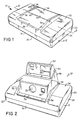
- Fig. 1 is a perspective view of an instant type folding camera whih embodies the present invention;
- Fig. 2 is a perspetive view of the camera of Fig. 1 shown in its erected operative position;
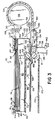
- Fig. 3 is an enlarged partial view of the camera taken generally along the line 3-3 in Fig. 1 with parts omitted for reasons of clarity;
- Fig. 4 is an enlarged perspective view showing the relationship between a photographic film assemblage, which forms a part of the invention, and a pivotally mounted supporting structure for the camera's first and second pressure-applying means;
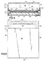
- Fig. 5 is an enlarged end view showing the relationship between a film cassette, an exposed film unit, and the second pressure-applying means during the spreading of a processing liquid between layers of the film unit, the film unit elements being greatly enlarged for clarity of understanding;
- Fig. 6 is a bottom view of the film cassette shown in Figs. 3-5;
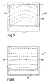
- Fig. 7 is a diagrammatic plan view of a film unit showing, in dotted lines, an advancing wave front of processing liquid as it would appear without benefit of the present invention; and
- Fig. 8 is a view similar to Fig. 7 showing, in dotted lines, an advancing wave front as it would appear with the present invention.
- Reference is now made to the drawings, and in particular to Figs. 1 and 2 wherein is shown a folding camera 10 of the instant or self-developing type. Note should be taken at this time that although the invention is desribed in relation to a folding camera, the invention is equally applicable to a non-folding camera. The camera 10 includes a first or
main housing 12 having aloading door 14 in a bottom wall thereof. Thefirst housing 12 also includes front andrear walls walls door 14 is pivotally connected to theend wall 22 of themain housing 12 by a hinge (not shown) which is generally parallel with the axis of the camera'sobjective lens 28 and perpendicular to the forward andrear walls main housing 12 further includes atop wall 30 having a pair of spacedflanges recess 36. - The camera 10 further includes a
second housing 38 which is pivotally coupled to thefirst housing 12 about an axis (not shown) which is generally parallel with therear wall 20 for movement between an inoperative position (see Fig. 1), wherein it is nested within therecess 36, and its operative position, as shown in Fig. 2. Thesecond housing 38 supports the aforementionedobjective lens 28, a shutter assembly, and aphotocell window 40. Atop wall 42 of the second housing includes arecess 44 which is adapted to receive athird housing 46 of the camera 10 when the camera is being collapsed or folded. - The
third housing 46 is pivotally coupled to therear wall 20 of thefirst housing 12 about a horizontal axis (not shown) which is generally parallel with therear wall 20. Thethird housing 46 is provided with arecess 50 for pivotally receiving therein afourth housings 52. - The
fourth housing 52 supports a source of artificial illumination such as astrobe 54 and a rangingwindow 56. Thefourth housing 52, as well as the second andthird housings fourth section 52 is adapted to be nested within therecess 50 prior to thethird housing 46 being moved into therecess 44. - When the various housings are in the positions shown in Fig. 2, actuation of an exposure cycle initiation button 58 (see Fig. 1) located within a recess in the
top wall 30 of thefirst housing 12 is effective to cause image bearing light rays to enter the camera 10 via thelens 28 and be reflected downwardly by a mirror (not shown) onto a film unit. - The camera 10 includes a film chamber 60 which is accessible via the
loading door 14. The film chamber 60 is adapted to receive afilm assemblage 70. The film chamber 60 is defined in part by awall 62 which functions to locate afilm cassette 72 of theassemblage 70 in position for the sequential exposure of a plurality offilm units 74 stacked therein. - The
film assemblage 70 includes, in addition to thefilm cassette 72 and thefilm units 74, biasing means (not shown) for resiliently urging the stack offilm units 74 toward aforward wall 76 of thefilm cassette 72. Theforward wall 76 is provided with a generally rectangular shaped exposure aperture 78 which is adapted to be located in alignment with a correspondingly shapedaperture 64 located in thewall 62. Theforward wall 76 cooperates with a pair ofside walls end walls bottom wall 88, to define a chamber for receiving the stack offilm units 74. The aforementioned biasing means is located between thebottom wall 88 and an adjacentendmost film unit 74 so as to urge the oppositeendmost film unit 74 in the stack against the interior surface of theforward wall 76 with 1) its photosensitive layer 90 (see Fig. 5) located in alignment with the exposure aperture 78, 2) its leading end located in position to be moved through anelongate egress 92 in the cassette'sleading end wall 84, and 3) its trailing end located adjacent the trailingend wall 86. The leading end of eachfilm unit 74 is provided with a pod orcontainer 94 of processing liquid 96 (see Fig. 5) and the trailing end of each film unit is formed with atrap 98 for receiving anyexcess processing liquid 96. - Extending downwardly from the
bottom wall 88 and integrally formed therewith is aprotuberance 100 which functions to control the distribution of the processing liquid to be spread between layers of an exposed film unit. Theprotuberance 100 slopes downwardly and rearwardly as it extends from theleading end wall 84 to its left terminus 102 (as viewed in Fig. 3) to define asurface 104 having upwardly sloping lateral ends 106 and 108 (see Fig. 5). - The
side wall 84 of thefilm cassette 72 has atab 110 which extends outwardly therefrom. As will be more fully described hereinafter, thetab 110 is adapted to cooperate with camera structure to adjust the location of a pressure-generating gap relative to a path of travel of an exposed film unit as the latter enters the gap so as to increase or decrease the thickness of a layer of processing liquid to be spread between layers or elements of the film unit. - The camera 10 includes a
structure 112 for supporting 1) a first pressure-applying means in the form ofelongate spread rollers plate 118. The opposite ends of thespread rollers arms pressure generating gap 124 therebetween. Theroller 116 is mounted for movement toward and away from theroller 114. The opposite ends of thearms cylindrical rod 126. In Fig. 3, thearm 120 is shown in phantom lines so as to provide a better view of the camera's first and second pressure-applying means and thesurfaces protuberance 100. Also in Fig. 3, thepressure generating gap 124 is shown as being located in alignment with a path of travel that an exposedfilm unit 74 would take as it moves from thefilm cassette 72 to afilm storage chamber 128, said path of travel being indicated by theline 130. Theplate 118 extends between the ends of another pair ofarms rod 126. Thus, as best seen in Fig. 4, the second pressure-applying means is adapted to be independently rotated about therod 126 without affecting the movement of the first pressure-applying means. Suitable means, such as a spring schematically shown in Fig. 3 at 136, is provided for resiliently biasing the arm(s) 134 and 136 in a clockwise direction against a stop (not shown). Aseparate spring 138 is provided for resiliently biasing the arm(s) 132 and 134 in a clockwise direction into engagement with astop 140. The force of thespring 138 may be increased or decreased by moving an adjustingcam 142 to the left or right, respectively, as shown in Fig. 3. - When a
film cassette 72 is positioned within the film chamber 60, thetab 110 engages an upwardly extendingportion 144 of thearm 120 and causes the first pressure-applying means (arms rollers 116 and 112) to be rotated in a counterclockwise direction about therod 126 until thefilm cassette 72 is in the position shown in Fig. 3 and thegap 124 properly located relative to the path oftravel 130; the degree of such rotation being a function of the thickness of thetab 110 or its location on the side wall of thefilm cassette 72, which in turn is a function of a predetermined desired thickness for a layer of processingliquid 96 to be spread between layers of the particular film units located in thefilm cassette 72. - At the same time that the above spacial relationship between the
gap 124 and the path oftravel 130 is being established a second relationship is being established, namely, the juxtapositioning of theprotuberance 100 on thebottom wall 88 of thefilm cassette 72 and the second pressure-applying means (the plate 118). Preferably, this latter relationship is established by theprotuberance 100 lightly engaging the top surface of theplate 118 such that thesloping surface 104 of the protuberance cooperates with acurved surface 146 on theplate 118 to define a converging passage to facilitate the introduction of a film unit between theprotuberance 100 and theplate 118. Alternatively, thestop 140 may also function to provide for some initial gap between the two members. - Once the
film cassette 72 has been properly located in the position shown in Fig. 3, and the film assemblage's dark slide (not shown) removed thereby unccovering the upperendmost film unit 74 in the stack, actuation of thebutton 58 is effective to initiate an exposure cycle. Subsequent to the photographic exposure of theendmost film unit 74, a battery energized motor (not shown) is used to drive a film advancing member 144 (first advancing means) in a reciprocating manner such that it enters an ingress 146 (see Fig. 4) formed in the forward and trailingend walls film cassette 72 and engages the endmost film unit by its trailing edge and moves it in a first direction toward the exterior of thefilm cassette 72 via theegresss 92. As theendmost film unit 74 emerges from thefilm cassette 72, its leading end enters the bite between laterally spaced pairs ofedge rollers rollers endmost film unit 74 along thepath 130 in said first direction and then in a second direction, generally opposite to the first direction. Acurved passageway 152 defined by a laterally extendingcurved plate 154 and acylindrical member 156 facilitates such reversal. As the film unit's leading end emerges from thepassageway 152, it enters the bite of another set of laterally spaced pairs ofedge rollers 158 and 160 (only one pair shown) which continue the advancement of theendmost film unit 74 in the second direction as its trailing end leaves the bite of the first set ofedge rollers edge rollers lateral margins endmost film unit 74. Thus, the two sets of edge rollers and the means defining thecurved passageway 152 define a second means for continuing the movement of the endmost film unit in the first direction and then in a second direction generally opposite to the first direction. - The second set of pairs of
edge rollers protuberance 100 and the second pressure applying means (plate 118) and into the bite of thespread rollers rollers container 94 of processing liquid and spread itscontents 96 in a layer between elements of the film unit, e.g., thephotosensitive sheet 90 and an image-receivingsheet 162, so as to initiate the formation of a visible image within thesheet 162 while simultaneously advancing the film unit into thelighttight storage chamber 128. As thefilm unit 74 enters thechamber 128, its leading end engages a pair oframps 166 166 (only one shown) located on the right hand ends of a pair (only one shown) of inwardly extendinghorizontal surfaces 168. The drive of thespread rollers film unit 74 up theramps 166 and onto thesurfaces 168 which function to support only thelateral sides film unit 74 to reach a point where its emerging image is no longer susceptible to being adversely affected by ambient light, anopaque shade 170 may be moved from covering relation to awindow 172 in thedoor 14 to allow viewing of the image within thefilm unit 74. The film unit may then be removed from thefilm chamber 128 via an exit (not shown) or left in place and theshade 170 returned to its lighttight position relative to thewindow 172 in preparation for a second exposure. Eachsubsequent film unit 74 entering thestorage chamber 128 will automatically assume thelowermost position because of the placement of theramps 166, thus assuring that the last film unit to be exposed will be available for viewing while in the storage chamber. - When the
spread rollers pod 94 at the leading end of the exposedfilm unit 74, theprocessing liquid 96 emerges therefrom as a wave whose front is controlled by the specific shape of theprotuberance 100. In the present form of the invention, theintermediate portion 104 of theprotuberance 100 retards the adjacent portion of the wave front of theprocessing liquid 96 while the upwardly tapering or sloping lateral ends 106 and 108 gradually offer less and less resistance to the adjacent portions of the wave front. Thus, the net effect of theprotuberance 100 on the wave front is to straighten out its normally tongue shape configuration, as shown in Fig. 7 whereopposite end corners film unit 74 thereby providing a more uniform distribution of theprocessing liquid 96. - Since certain changes may be made in the above described invention without departing from the scope thereof, it is intended that all matter contained in the above description or shown in the accompanying drawings shall be interpreted as illustrative and not in a limiting sense. For example, while the
protuberance 100 has been shown as a unitary member having a specific configuration, it could be comprised of a plurality of separate smaller members whose configurations and spacial relation to each other would be a function of the specific control to be applied to the wave front of the processing liquid.
Claims (12)
- Photographic apparatus of the self-developing type for use with a film cassette (72) having a chamber defined by forward (76) and rear walls (88) interconnected by a pair of side walls (80, 82), a leading end wall (84) and a trailing end wall (86), said forward wall (76) comprises an exposure aperture (78) and said leading end wall (84) comprises an elongate film advancing egress (92); a plurality of film units (74) located within said chamber in stacked relation with an endmost film unit in said stack being urged into a position adjacent said exposure aperture (78) with a leading edge aligned with said egress (92), each of said film units (74) include a container (94) of processing liquid (96) at its leading edge; wherein a protuberance (100) extends from the bottom wall of said cassette (72) and the protuberance slopes downwardly and rearwardly as it extends from the leading endwall (84), said apparatus comprising:- a film chamber (60) for locating said film cassette (72) in position for the sequential exposure of said film units (74);- first film advancing means (144) for advancing said endmost film unit in a first direction, subsequent to its exposure, towards the exterior of said film cassette (72);- second film advancing means (148, 150; 154; 158, 160) for continuing the movement of said endmost film unit in said first direction and then in a second direction generally opposite to said first direction;- first pressure-applying means (114, 116) mounted in the path of travel of said endmost film unit as it is being advanced in said second direction, said first pressure-applying means (114, 116) being adapted to spread said processing liquid (96) across a layer of said endmost film unit to initiate the formation of a visible image within said endmost film unit;- a laterally extending pressure plate (118) mounted within said apparatus;- the support for the film cassette supports the cassette in such a position within the photographic apparatus that a gap is formed between the protuberance (100) of the cassette (72) and the plate (118) of the apparatus so as to form second pressure-applying means (104, 106, 108; 118) in the second direction path of movement upstream of said first pressure-applying means (114, 116) for controlling liquid distribution;- the photographic apparatus comprises biasing means for biasing the pressure plate (118) towards the protuberance (100) of the inserted cassette;- said first pressure-applying means (114, 116) is disposed within the path of travel of the film unit, on the downstream side of said gap of said second pressure-applying means;- said second pressure-applying means are mounted in position so that a major surface of the endmost film unit is engaged during the spreading of said processing liquid (96) by said plate (118) and its opposite surface is urged in engagement with a processing liquid spread control surface (104, 106, 108) of said protuberance so as to control the distribution of the processing liquid being spread by said first pressure applying means (114, 116).
- Photographic apparatus as defined in claim 1 wherein said first pressure-applying means comprises a pair of rollers (114, 116), which define a pressure generating gap (124) through which said endmost film unit is moved, said photographic apparatus further includes a common support (112) for said rollers (114, 116), which is rotatably mounted by a rod (126) in the photographic apparatus.
- Photographic apparatus as defined in claim 2 wherein said film cassette further includes extensions (110) on a side wall (80) thereof and wherein said support (112) abuts said extension (110) for locating said pressure generating gap (124) of said rollers (114,116) relative to said path of travel of said endmost film unit in said second direction.
- Photographic apparatus as defined in claim 3 wherein said support (112) rotatably mounts said pressure-applying plate (118) for movement toward and away from said surface (104, 106, 108).
- Photographic apparatus as defined in claim 4 wherein said pressure plate (118) extends between a pair of arms (132,134) rotatably mounted about said rod (126).
- Photographic apparatus as defined in claim 1 further including a spring (138) for biasing said plate (118) of said second pressure-applying means toward said processing liquid spread control surface (104, 106, 108).
- Photographic apparatus as defined in claim 6 further including means (142) for regulating the force of said spring (138).
- Photographic apparatus as defined in claim 7 wherein said regulating means includes a cam (142).
- A photographic film cassette (72) for use with a camera of the self-developing type having first pressure-applying means (114, 116) having a pressure generating gap (124) for spreading a processing liquid across a layer of an exposed film unit to initiate the formation of a visible image therein, and first and second film advancing means for moving the film unit in a first and a second direction opposite thereto, the movement in said second direction is effected in a path below the bottom wall of said cassette; wherein said cassette (72) comprises one first portion (100) of a second pressure-applying means for simultaneously urging the exposed film unit into engagement with an other surface, said film cassette (72) comprises:- a chamber defined by forward (76) and rear walls (88), a pair of laterally spaced side walls (80, 82), and leading and trailing end walls (84, 86), said forward wall (76) includes an exposure aperture (78) therein and said leading end wall (84) includes an egress (92) through which a film unit may be moved from said chamber;- a plurality of film units (74) located within said chamber in stacked relation with an endmost film unit in said stack being adapted to be urged into a position adjacent said exposure aperture with a leading edge of said endmost film unit being located in position to be moved through said egress, each of said film units including a supply of processing liquid, each of said film units being adapted to be moved from said film cassette via said egress and along a path of travel in the photographic apparatus subsequent to its exposure, which movement includes passage through the pressure generating gap (124);wherein said first portion (100) of said second pressure-applying means is defined by a processing liquid spread control surface (104, 106, 108) extending from the bottom wall of said film cassette, and said processing liquid spread control surface is adapted to cooperate with a second portion (118) of said second pressure-applying means defined by said photographic apparatus for controlling the spreading of said processing liquid by the first pressure-applying means (114, 116).
- A photographic film cassette as defined in claim 9 wherein said processing liquid spread control surface is integrally formed in an external surface of said bottom wall.
- A photographic film cassette as defined in claim 9 wherein said film cassette further includes an extension (110) extending from an external surface (80) thereof and adapted to engage the photographic apparatus's first pressure-applying means for adjusting the position of its pressure generating gap (124) relative to the path of travel of a film unit subsequent to its photographic exposure.
- A photographic film cassette as defined in claim 11 wherein said extension (110) is integrally formed in one (80) of said side walls.
Applications Claiming Priority (2)
| Application Number | Priority Date | Filing Date | Title |
|---|---|---|---|
| US188970 | 1988-05-02 | ||
| US07/188,970 US4839676A (en) | 1988-05-02 | 1988-05-02 | Film cassette-liquid spread roller assembly interface |
Publications (2)
| Publication Number | Publication Date |
|---|---|
| EP0340682A1 EP0340682A1 (en) | 1989-11-08 |
| EP0340682B1 true EP0340682B1 (en) | 1994-05-25 |
Family
ID=22695336
Family Applications (1)
| Application Number | Title | Priority Date | Filing Date |
|---|---|---|---|
| EP89107805A Expired - Lifetime EP0340682B1 (en) | 1988-05-02 | 1989-04-28 | Film cassette-liquid spread roller assembly interface |
Country Status (5)
| Country | Link |
|---|---|
| US (1) | US4839676A (en) |
| EP (1) | EP0340682B1 (en) |
| JP (1) | JP2725833B2 (en) |
| CA (1) | CA1305623C (en) |
| DE (1) | DE68915475T2 (en) |
Families Citing this family (9)
| Publication number | Priority date | Publication date | Assignee | Title |
|---|---|---|---|---|
| JPH02287527A (en) * | 1989-04-28 | 1990-11-27 | Fuji Photo Film Co Ltd | Video printer |
| US5019842A (en) * | 1989-12-29 | 1991-05-28 | Polaroid Corporation | Extendable shade in instant camera for protecting film unit from ambient light |
| US5049907A (en) * | 1990-11-08 | 1991-09-17 | Polaroid Corporation | Camera having chamber for storing exposed film units during their development |
| US5619292A (en) * | 1994-05-24 | 1997-04-08 | Olympus Optical Co., Ltd. | Camera |
| EP1892568A3 (en) * | 1999-07-02 | 2011-11-23 | FUJIFILM Corporation | Method of and apparatus for manufacturing instant film unit |
| US6795114B1 (en) | 2000-01-31 | 2004-09-21 | Polaroid Corporation | Film unit drive assembly for a detachable electronic photographic printer and camera |
| US6417911B1 (en) | 2000-01-31 | 2002-07-09 | Polaroid Corporation | Processing fluid spread system for an electronic photographic printer and camera and related method thereof |
| US6330397B1 (en) | 2000-01-31 | 2001-12-11 | Polaroid Corporation | Film unit drive assembly for an electronic photographic printer and camera and related method thereof |
| US6317561B1 (en) | 2000-01-31 | 2001-11-13 | Polaroid Corporation | Processing fluid spread system for a detachable electronic photographic printer and camera |
Family Cites Families (13)
| Publication number | Priority date | Publication date | Assignee | Title |
|---|---|---|---|---|
| US3460452A (en) * | 1967-09-18 | 1969-08-12 | Polaroid Corp | Self-developing camera and process performed therein |
| US3421468A (en) * | 1968-04-16 | 1969-01-14 | Bobby G Newsom | Hydrofoil craft |
| US3722383A (en) * | 1970-06-30 | 1973-03-27 | Polaroid Corp | Unique waste-free camera system of the self-developing type |
| US3810211A (en) * | 1972-04-24 | 1974-05-07 | Polaroid Corp | Self-developing camera system |
| US3779770A (en) * | 1972-04-24 | 1973-12-18 | Polaroid Corp | A photographic film assemblage for a diffusion transfer film |
| US3777647A (en) * | 1972-05-23 | 1973-12-11 | Polaroid Corp | Photographic apparatus and method for treating photographic materials with a liquid |
| US3832731A (en) * | 1973-04-26 | 1974-08-27 | Polaroid Corp | Photographic film assemblage |
| US4104669A (en) * | 1977-04-15 | 1978-08-01 | Polaroid Corporation | Thermally responsive photographic processing apparatus for use with self-processable film units |
| US4226519A (en) * | 1979-04-02 | 1980-10-07 | Polaroid Corporation | Self-developing film pack with improved spread control structure |
| US4545663A (en) * | 1982-12-27 | 1985-10-08 | Polaroid Corporation | Integral self-developing film unit and system for use thereof |
| US4693963A (en) * | 1986-04-01 | 1987-09-15 | Polaroid Corporation | Self-developing integral film unit |
| US4664497A (en) * | 1986-07-02 | 1987-05-12 | Polaroid Corporation | Camera having chamber for storing exposed film units during their development |
| US4688912A (en) * | 1986-11-20 | 1987-08-25 | Polaroid Corporation | Photographic apparatus having a film advancing and processing assembly |
-
1988
- 1988-05-02 US US07/188,970 patent/US4839676A/en not_active Expired - Lifetime
-
1989
- 1989-04-12 CA CA000596418A patent/CA1305623C/en not_active Expired - Fee Related
- 1989-04-27 JP JP1106134A patent/JP2725833B2/en not_active Expired - Lifetime
- 1989-04-28 EP EP89107805A patent/EP0340682B1/en not_active Expired - Lifetime
- 1989-04-28 DE DE68915475T patent/DE68915475T2/en not_active Expired - Fee Related
Non-Patent Citations (1)
| Title |
|---|
| RESEARCH DISCLOSURE, no. 191, March 1980, pp. 107,108, London, GB ; H. ETTISCHER : "Film unit deflecting means for instant picture camera". * |
Also Published As
| Publication number | Publication date |
|---|---|
| EP0340682A1 (en) | 1989-11-08 |
| JPH02146029A (en) | 1990-06-05 |
| DE68915475D1 (en) | 1994-06-30 |
| US4839676A (en) | 1989-06-13 |
| CA1305623C (en) | 1992-07-28 |
| JP2725833B2 (en) | 1998-03-11 |
| DE68915475T2 (en) | 1994-09-08 |
Similar Documents
| Publication | Publication Date | Title |
|---|---|---|
| US3948662A (en) | Method of processing film unit with processing solution wave front modifying means | |
| US4723140A (en) | Compact folding camera construction | |
| US4839676A (en) | Film cassette-liquid spread roller assembly interface | |
| US4389110A (en) | Folding camera | |
| US4226519A (en) | Self-developing film pack with improved spread control structure | |
| US3537370A (en) | Camera structure | |
| US3405619A (en) | Camera and film useful therein | |
| US4392732A (en) | Folding camera with viewfinder having independently mounted optical elements | |
| US4387978A (en) | Folding camera with pivotally mounted viewfinder | |
| US4064518A (en) | Compact self-developing camera with folded optical image path | |
| US4104669A (en) | Thermally responsive photographic processing apparatus for use with self-processable film units | |
| US4174164A (en) | Photographic processing apparatus | |
| EP0487508B1 (en) | Photographic apparatus | |
| US4087831A (en) | Bearing block mount for a photographic fluid spreading apparatus | |
| US3589262A (en) | Photographic processing apparatus | |
| US3994002A (en) | Self-developing camera with film unit deflecting structure | |
| EP0268132B1 (en) | Photographic apparatus having a film advancing and processing assembly | |
| JPS607772B2 (en) | photographic equipment | |
| US3820137A (en) | Photographic apparatus | |
| US3270643A (en) | Photographic apparatus | |
| US4395102A (en) | Bellows for folding camera | |
| US4755839A (en) | Pivotally mounted spread roller assembly | |
| US5049907A (en) | Camera having chamber for storing exposed film units during their development | |
| US3320865A (en) | Self-developing photographic camera | |
| US3952835A (en) | Flat torque rate drive system |
Legal Events
| Date | Code | Title | Description |
|---|---|---|---|
| PUAI | Public reference made under article 153(3) epc to a published international application that has entered the european phase |
Free format text: ORIGINAL CODE: 0009012 |
|
| AK | Designated contracting states |
Kind code of ref document: A1 Designated state(s): DE FR GB |
|
| 17P | Request for examination filed |
Effective date: 19900425 |
|
| 17Q | First examination report despatched |
Effective date: 19920602 |
|
| GRAA | (expected) grant |
Free format text: ORIGINAL CODE: 0009210 |
|
| AK | Designated contracting states |
Kind code of ref document: B1 Designated state(s): DE FR GB |
|
| ET | Fr: translation filed | ||
| REF | Corresponds to: |
Ref document number: 68915475 Country of ref document: DE Date of ref document: 19940630 |
|
| PLBE | No opposition filed within time limit |
Free format text: ORIGINAL CODE: 0009261 |
|
| STAA | Information on the status of an ep patent application or granted ep patent |
Free format text: STATUS: NO OPPOSITION FILED WITHIN TIME LIMIT |
|
| 26N | No opposition filed | ||
| PGFP | Annual fee paid to national office [announced via postgrant information from national office to epo] |
Ref country code: FR Payment date: 20000313 Year of fee payment: 12 |
|
| PGFP | Annual fee paid to national office [announced via postgrant information from national office to epo] |
Ref country code: GB Payment date: 20000321 Year of fee payment: 12 |
|
| PGFP | Annual fee paid to national office [announced via postgrant information from national office to epo] |
Ref country code: DE Payment date: 20000324 Year of fee payment: 12 |
|
| PG25 | Lapsed in a contracting state [announced via postgrant information from national office to epo] |
Ref country code: GB Free format text: LAPSE BECAUSE OF NON-PAYMENT OF DUE FEES Effective date: 20010428 |
|
| PG25 | Lapsed in a contracting state [announced via postgrant information from national office to epo] |
Ref country code: FR Free format text: THE PATENT HAS BEEN ANNULLED BY A DECISION OF A NATIONAL AUTHORITY Effective date: 20010430 |
|
| GBPC | Gb: european patent ceased through non-payment of renewal fee |
Effective date: 20010428 |
|
| PG25 | Lapsed in a contracting state [announced via postgrant information from national office to epo] |
Ref country code: DE Free format text: LAPSE BECAUSE OF NON-PAYMENT OF DUE FEES Effective date: 20020201 |
|
| REG | Reference to a national code |
Ref country code: FR Ref legal event code: ST |