EP0340271B1 - Apparatus for checking dimensions of workpieces - Google Patents
Apparatus for checking dimensions of workpieces Download PDFInfo
- Publication number
- EP0340271B1 EP0340271B1 EP88909605A EP88909605A EP0340271B1 EP 0340271 B1 EP0340271 B1 EP 0340271B1 EP 88909605 A EP88909605 A EP 88909605A EP 88909605 A EP88909605 A EP 88909605A EP 0340271 B1 EP0340271 B1 EP 0340271B1
- Authority
- EP
- European Patent Office
- Prior art keywords
- support frame
- coupling
- workpiece
- frame
- support structure
- Prior art date
- Legal status (The legal status is an assumption and is not a legal conclusion. Google has not performed a legal analysis and makes no representation as to the accuracy of the status listed.)
- Expired - Lifetime
Links
Images





Classifications
-
- G—PHYSICS
- G01—MEASURING; TESTING
- G01B—MEASURING LENGTH, THICKNESS OR SIMILAR LINEAR DIMENSIONS; MEASURING ANGLES; MEASURING AREAS; MEASURING IRREGULARITIES OF SURFACES OR CONTOURS
- G01B5/00—Measuring arrangements characterised by the use of mechanical techniques
-
- G—PHYSICS
- G01—MEASURING; TESTING
- G01B—MEASURING LENGTH, THICKNESS OR SIMILAR LINEAR DIMENSIONS; MEASURING ANGLES; MEASURING AREAS; MEASURING IRREGULARITIES OF SURFACES OR CONTOURS
- G01B7/00—Measuring arrangements characterised by the use of electric or magnetic techniques
- G01B7/12—Measuring arrangements characterised by the use of electric or magnetic techniques for measuring diameters
-
- B—PERFORMING OPERATIONS; TRANSPORTING
- B23—MACHINE TOOLS; METAL-WORKING NOT OTHERWISE PROVIDED FOR
- B23Q—DETAILS, COMPONENTS, OR ACCESSORIES FOR MACHINE TOOLS, e.g. ARRANGEMENTS FOR COPYING OR CONTROLLING; MACHINE TOOLS IN GENERAL CHARACTERISED BY THE CONSTRUCTION OF PARTICULAR DETAILS OR COMPONENTS; COMBINATIONS OR ASSOCIATIONS OF METAL-WORKING MACHINES, NOT DIRECTED TO A PARTICULAR RESULT
- B23Q1/00—Members which are comprised in the general build-up of a form of machine, particularly relatively large fixed members
- B23Q1/01—Frames, beds, pillars or like members; Arrangement of ways
Definitions
- EP-A-0340272 claims an apparatus for checking workpieces featuring a particular arrangement and coupling between support means supporting the workpiece, a counterbalanced support structure, rotatable about a horizontal axis and including a frame, and gauges fixed to the frame and movable with the support structure to be moved in and out of a measuring position, for going into cooperation with the workpiece, in a direction essentially horizontally tangential to the workpiece.
- the invention relates to an apparatus for checking dimensions of workpieces, with a support structure; reference and support means, coupled to the support structure, for supporting and positioning the workpiece to be checked; a main support frame carried by the support structure; an elongate additional support frame carried by the main support frame; coupling means for coupling the main support frame to the support structure and the additional support frame to the main support frame, the coupling means including a coupling device coupling the additional support frame to the main support frame, substantially at a single zone of the additional support frame; and measuring means including first measuring means fixed to the main support frame and second measuring means secured along the additional support frame, the second measuring means including a plurality of measuring units for providing corresponding measurement signals to be processed for performing combined measurements.
- U.S. patent US-A-4233744 to Possati relates to a bench gauge including a support structure carrying a nosepiece ensuring centering and providing a mechanical reference for a workpiece to be checked.
- a support frame consisting of a plate with three guide slots is coupled to the support structure through three connection elements having a flexible section and arranged at spaced apart locations, in order to reduce the transmission to the plate of stresses and deformations originated in the support structure.
- the plate carries a plurality of measuring heads, each of which is coupled to the plate by a plurality of spaced apart connection screws passing through one of the slots.
- the bench gauge is adapted for checking, statically or dynamically, inside diameters, outside diameters and other characteristics, in particular by combining the signals of different measuring heads.
- French patent FR-A-1507371 discloses a modular apparatus for checking features of workpieces, in particular linear dimensions of workpieces having rotational symmetry.
- the modular components of the apparatus include base plates with slots for positioning and locking other components, among which rest devices for defining the position of the workpiece to be checked, supports and slides for carrying gauges and/or for carrying frames adjustably supporting one or more gauges.
- a base plate carries two vee blocks for supporting the workpiece and a cylindrical rod for supporting several gauging heads, adjustable along the rod. The rod is secured to the base plate, through two supports coupled to the ends of the rod and to spaced apart zones at a side of the base plate.
- a base plate carries a horizontal slide for displacing the workpiece to a measurement position and first and second measuring means carried by corresponding supports.
- a vertical rod coupled to the base plate carries the first measuring means and the second measuring means are carried by an elongate frame slidably coupled to the vertical rod through a coupling element.
- the second measuring means consist of a plurality of measuring devices for performing combined measurements. These measuring devices are simultaneously displaced into cooperation with the workpiece by causing the elongate frame to vertically slide with respect to the vertical rod.
- U.S. patent US-A-3905116 relates to an apparatus for measuring crankshafts, including a base, a tailstock and a headstock secured to the base for supporting the crankshaft at its ends, and a carriage mounted on rails parallel to the axis of the crankshaft.
- a measuring system including a scale and a digital readout, provides a signal responsive to the position of the carriage relative to a base point.
- the carriage carries, through two trunnion bearings, a probe including a slidable shaft having at one end a tip for subsequently contacting different surfaces of the crankshaft, for determining, by means of the measuring system, axial locations and distances of the crankshaft surfaces.
- U.S. patent US-A-3011780 relates to a universal gauging device comprising a bed carrying support and reference means, including an adjustable finger and an adjustable stop member for locating the workpiece to be measured.
- the measurements are performed by means of two dial gauges carried by distinct and spaced apart mounting devices, which are coupled to the bed and permit adjustment of the positions of the dial gauges.
- the invention is intended to overcome the drawbacks of the prior art, by permitting the obtainment of an apparatus in which measuring means - in particular measuring means providing signals adapted to be processed for performing combined measurements - are carried by a support frame that is not subject to substantial stresses and deformations causing modification of the mutual arrangement of the measuring means.
- an apparatus for checking dimensions of workpieces comprises a support structure; reference and support means coupled to the support structure for supporting and positioning the workpiece to be checked; a main support frame carried by the support structure; an elongate additional support frame carried by the main support frame; coupling means for coupling the main support frame to the support structure and the additional support frame to the main support frame, the coupling means including a coupling device coupling the additional support frame to the main support frame, substantially at a single zone of the additional support frame; and measuring means including first measuring means (170) fixed to the main support frame and second measuring means secured along the additional support frame, the second measuring means including a plurality of measuring units for providing corresponding measurement signals to be processed for performing combined measurements.
- the coupling device fixes the additional support frame, at a substantially intermediate zone, to the main support frame, for limiting the occurrence of external forces applied to the additional support frame substantially at said single, intermediate zone and preventing thereby substantial deformations of the additional support frame
- the coupling means comprise movable elements coupled to the support structure to define an axis for the rotation of the main support frame with respect to the support structure, to displace the measuring means into cooperation with the workpiece.
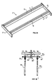
- the bench gauge shown in figures 1 and 2 comprises a support structure including a base, or bed 2 (also shown in figure 3), with two pairs of longitudinal bars having a rectangular cross-section 4, 6 and 8, 10 fixed at their ends in a mutually parallel way to two crosspieces 12 and 14. Coupling may be made, for example, by welding. Longitudinal openings 16 and 18 defined by the pairs of longitudinal parallel bars 4, 6 and 8, 10, respectively, form longitudinal guides.
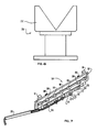
- a protection structure 20 (also shown in figures 4A and 4B) comprises two halfshells 22 and 24 joined at the base by two parallel flat bars 26 and 28.
- Structure 20 is positioned on bed 2 in such a way that the flat bars 26, 28 are arranged in a transversal position with respect to the two pairs of bars 4, 6 and 8, 10. Both flat bars 26, 28 have two through holes 30 and 32 (just those of flat bar 26 are shown in figure 4A) formed in such positions so as to arrange themselves in correspondence to openings 16 and 18, respectively. Structure 20 is secured to bed 2 by means of bolts (as an example just one is shown in figure 4A) consisting of screws 34 with a hexagonal head inserted in openings 16 (18) and in through holes 30 (32), and of nuts 36 that are fastened to said screws so contacting against the upper surface of flat bars 26, 28; the heads of screws 34 are thus urged against the bottom surface of bars 4, 6 (8, 10).
- bolts as an example just one is shown in figure 4A
- Reference and support means comprise two rest devices 40 (only one is shown in figure 1), for supporting a workpiece 42 to be checked with its geometrical axis horizontally arranged.
- the rest devices 40 comprise support members 44 arranged on base 2 according to mutually parallel transversal directions and pairs of reference elements 46, 48 each adapted for being secured to one of said members 44.
- the reference elements, and more specifically element 46 have a first portion 50 with two rest surfaces 52 and 54 that have a different inclination, adapted for being arranged in a symmetrical way with respect to similar surfaces of element 48 and about an axis defined by associated support member 44, in such a way so as to define V-shaped rests for workpiece 42 with different sloping surfaces if the sides of the V are the pairs of surfaces 52 or 54 respectively.
- Reference element 46 (just like element 48) further comprises a clamping portion with two parallel blocks 56 and 58 coupled, for example welded, to the first portion 50 and with a free end, that define an opening 60; the width of said opening 60 is limited, near the free ends of blocks 56 and 58, by welding spots 62 and 64.
- An end part of portion 50 opposite to rest surfaces 52 and 54 forms a centering overhang 66.
- Support member 44 basically comprises three parts: a coupling portion 68, a central body 70 and a support part 72.
- the coupling portion 68 shown in figure 2 only, comprises two through holes for the coupling of the whole rest device 40 to bed 2, and more specifically to the pairs of longitudinal bars 4, 6 and 8, 10, in a completely similar way as that described for the protection structure 20.
- Portion 68 of member 44 is fully identical to a part 98 shown in figures 1 and 2 (and pertaining to another device of the bench gauge) that will be described hereinafter and is coupled to bed 2 in the same way as this one. It should be realized that this particular method of coupling enables a continuous adjustment of the longitudinal position of the rest devices 40.
- Support part 72 comprises two elongated portions with an "L" shaped section 74 and 76, coupled near the upper edges of the central body 70 in such a way that the bases of the Ls face each other so as to form a transversal seat 78.
- the fixing of each of reference elements 46, 48 to coupling portion 68 of support member 44 is made in the following way: element 46 (48) is placed on body 70 so that overhang 66 is inserted in seat 78 and blocks 56 and 58 rest on portions 74 and 76, respectively.
- a screw 80 is inserted between portions 74, 76 in such a way that its threaded part protrudes in between the bases of the Ls in seat 78 and is inserted in opening 60 of element 46 (and is held there thanks to welding spots 62, 64 that limit the opening width at the open end).
- a nut 82 locked at the end of screw 80 urges against surfaces of blocks 56, 58, and consequently the head of screw 80 is clamped against internal surfaces of sections 74, 76. This clamping of screw 80 and the cooperating of overhang 66 against the surfaces of seat 78 so bring about the locking of element 46 to support member 44.
- element 48 is also clamped to support member 44.
- Coupling means comprise another support structure 88 including rotary arms 90 and 92 connected to support devices or supports 94 and 96 secured to bed 2.
- arms 90, 92 and associated supports 94, 96 are similar to each other, the description hereinafter refers to arm 90 and associated support 94 only, as shown in figures 1 and 2.
- Support 94 comprises a portion 98 for coupling to bed 2, a fulcrum section 100 that defines, together with the corresponding fulcrum section of support 96, an axis of rotation for arms 90, 92 and for the entire support structure 88, and a limit stop part 102.
- Portion 98 has two through holes 104 and 106, specifically placed in positions so as to be arranged in correspondence to openings 16 and 18, respectively, when support 94 rests on bed 2.
- Support 94 is secured to bed 2 by means of bolts consisting in screws 108, 110 that are inserted in openings 16, 18 and in through holes 104, 106 and nuts 112, 114 that are locked to said screws urging against the upper surface of portion 98; the heads of screws 108, 110 are thus urged against the bottom surface of the pairs of bars 4, 6 and 8, 10.
- the fulcrum section 100 comprises two rectangular plates 116, 118, having edges coupled (for example welded) to portion 98, so as to arrange themselves in a vertical and parallel way with respect to each other.
- Plates 116, 118 have through holes 120, 122 that are aligned along an axis of rotation, and the plates are joined to limit stop part 102, at their edges opposite the above mentioned edges.
- the latter part 102 substantially comprises two rectangular reciprocally sloping portions 124, 126, one of which, 124, is horizontally arranged and coupled (welded) to the edges of plates 116, 118, as previously mentioned; the other portion, 126, carries a reference abutment 128.
- Rotary arm 90 comprises: a first elongated portion 132, a second elongated portion 134 - angularly coupled to the first - a third elongated portion 136 with a circular cross-section, an annular portion 138 - that connects said second and third elongated portions 134 and 136 in such a way that these portions 134, 136 are reciprocally sloping -, the annular portion 138 comprising a hole 140 with an axis arranged transversally with respect to elongated portions 134, 136, and a counterweight end portion 142 connected to the third elongated portion 136.
- Arm 90 is inserted between plates 116, 118 of fulcrum section 100 of support 94, in such a way that the transversal axis of hole 140 is aligned with the above mentioned axis of rotation.
- a cylindrical pin 144 is inserted through hole 140 of portion 138 and holes 120, 122 of plates 116, 118 so as to connect arm 90 to support 94 in such a way that the latter may rotate about said axis of rotation.
- a first reference abutment element 146 is fixed to the second elongated portion 134 and is adapted for cooperating with reference abutment 128 for limiting the rotation of arm 90 in a clockwise direction (as shown in figure 1).
- a second reference abutment element 148 is coupled to portion 134, opposite to element 146, and a limit stop cap 150 is coupled to nut 112; element 148 and limit stop cap 150 cooperate for limiting the rotation of arm 90 in a direction opposite to the previously mentioned one.
- the first portion 132 of arm 90 has a through hole 152.
- the support structure 88 also comprises a main supporting frame 154, shown in figure 2, with two bars 156, 158 connected by segments 160, 162 coupled (welded) at their ends in such a way that bars 156, 158 are parallel and separated by a longitudinal opening 164 that forms a guide.
- Frame 154 is coupled to rotary arms 90, 92: more specifically it is fixed to the first elongated portions 132 by means of screws 166, that are inserted through holes 152 and opening 164 and then locked by nuts 168, according to the same method of clamping the various parts of the bench gauge to bed 2.
- Sensing or measuring means comprise gauges 170 of the "snap" type (only one of them is shown in figure 1) with an integral element 172 that has a coupling portion 174, two shaped end portions 176, 178 that carry feelers 180, 182 adapted for contacting the surface of workpiece 42, and two portions with a thinner section 184, 186 between the end portions and the coupling portion.
- the portions that have a thinner section 184, 186 allow end portions 176, 178 to accomplish limited rotational displacements with respect to the coupling portion 174.
- Resilient means 188 adapted for urging the end portions 176, 178 to a mutual approach
- limiting means 190 adapted for limiting the reciprocal displacements of end portions 176, 178
- transducer means 192 adapted for emitting electrical signals that depend on said mutual displacements, are coupled to both said end portions 176, 178.
- a hole in portion 174 allows the coupling of gauge 170 to frame 154 by means of a screw 198 that passes through opening 164 and the aforementioned hole and is locked by a nut 200.
- An additional support frame 210 comprises two bars 212, 214 - that are similar to bars 156, 158 but shorter - and two segments 216, 218 that join the bar ends, an opening 220 being defined between bars 212, 214 so as to provide a guide.
- a spacer block 222 arranged at the intermediate zone of support frame 210 has a through hole 224 for housing a screw 226; moreover the latter is inserted through openings 220 and 164, and locked to a nut 228 so as to clamp support frame 210 to main frame 154.
- Second sensing or measuring means, or gauges, 230 similar to gauge 170 are fixed to support frame 210 according to the same coupling method used for coupling gauge 170 to frame 154.
- the transducer means 192 of gauge 170 can comprise a single transducer
- each gauge 230 for diameter checking normally comprises two transducers.
- further gauges for determining axial dimensions can be fixed to support frame 210.
- gauges 170 carried by main frame 154 are used for performing single relevant measurements, while gauges 230 carried by frame 210 are used for carrying out combined measurements (by processing the signals of gauges 230).
- the counterweight end portion 142 has a substantially parallelepided shape and is adapted for balancing the weight of the sensing means 170, 230 coupled to frames 154 and 210 located at the opposite side of rotary arm 90.
- gauges 170 on frame 154 can vary and/or depending on the presence or not of frame 210 with relevant gauges 230, it is possible to add to the counterweight end portion 142 additional elements 232, coupled by means of a screw 234 that crosses portion 142 and elements 232 by passing through holes that are not shown in figure 1, and is locked by a nut 236. In this way it is possible to keep substantially constant the force required to make arms 90, 92 rotate and bring gauges 170, 230 on to workpiece 42 to be checked.
- the shape and the positioning of rest devices 40 and supports 94, 96 of rotary arms 90, 92 are such that the axis of rotation of the support structure 88 and the axis of the workpiece 42 to be checked lie, the first below the second, in a vertical geometrical plane coincident with the viewing plane of figure 2.
- This arrangement enables to achieve a considerable reduction in the overall dimensions of the whole apparatus and simplifies the (manual or automatic) loading of workpiece 42 on rest devices 40 and at the same time protects the sensing means 170, 230, that are conveniently arranged apart from these devices.
- gauges 170 The particular coupling of gauges 170 to frame 154 by means of just one bolt further prevents each of the sensing means 170 from being affected by possible plays due to inexact alignment of the axes of rotation of arms 90, 92, and/or bending of some parts of the apparatus.
- a similar advantage is ensured to the second sensing means 230 coupled to the additional frame 210 in turn coupled by just one bolt to frame 154: possible misalignments among a plurality of gauges 230 coupled to support frame 210 due, for example, to clearances in the rotations of arms 90, 92 are prevented, allowing an improved accuracy and flexibility in checking axial distances, concentricity, parallelisms, etc.
- frame 210 can also be connected to frame 154 by means of two bolts positioned sufficiently close together, instead of one, in order to obtain the same result. It is pointed out that frame 210 does not carry reference devices, such as Vee devices, for cooperating with the workpiece 42 and that the forces between the feelers of gauges 230 and workpiece 42 are very small. Support frame 210 can be much longer than that shown in figures 2 and 5, but it and gauges 230 can be of very limited weight, therefore deformations of the frame 210 due to its own weight and to the weight of gauges 230 are very small, also in view of the coupling of frame 210 at an intermediate zone. Therefore, the external forces and the stresses acting on the support frame 210 only consist, basically, of the forces and stresses occurring at the limited zone next to screw 226 and spacer block 222.
- reference devices such as Vee devices
- Guide elements or bumpers 240, 242 are coupled to bed 2 by means of bolts, in a quite similar way as for the other elements described up to now - for example like support 94 in the case of arm 90.
- the guide elements 240, 242 are adapted for limiting in an axial direction the positioning of workpiece 42 (that is not shown in figure 2 for simplicity's sake).
- Threaded through holes 244 in the guide elements can be used for the initial adjustment of rest devices 40.
- pointed reference screws 246 are screwed down through said holes 244 with their points opposite to each other so as to carry a master piece in the correct position and suitably adjust devices 40 by setting the position of reference elements 46, 48 onto support member 44. Once the correct arrangement of devices 40 has been reached, pointed screws 246 are unscrewed and the workpieces 42 to be checked are directly placed on said devices.
- an additional protection element 250 coupled to bed 2 in a similar way as the others (i.e. locked to the pairs of bars 4, 6 and 8, 10 by means of bolts in correspondence to a portion quite similar to portion 98 shown in figure 1); said element 250 is shown in figure 6 and comprises a substantially flat and V-shaped portion 252 adapted to be arranged parallel to rest devices 40.
- the function of element 250 is that of supporting workpiece 42 in the event that the positioning of the rest devices 40 (more specifically of the reference elements 46, 48) is inexact, in order to prevent the workpiece 42 from colliding against other parts of the bench gauge during, for example, the automatic loading operation.
- FIG. 7 schematically shows some details - that are not shown in the other figures of the bench gauge described up to now.
- a plate 260 with holes 272 is secured to and below frame 154, by means of two bridge elements 262, 264 and screws and bolts 266 and 268.
- Locking elements 270 made of plastic comprise a cylindrical end (not visible in the figure) adapted for insertion in a relevant hole 272 of plate 260, and a substantially annular portion 274 with a slit 276.
- the locking elements 270 are inserted in holes 272 in correspondence to the position of sensing means 170, 230 coupled to main frame 154 (or to additional frame 210).
- the sensing means are not explicitly shown, but just indicated by associated locking screws 198.
- Each cable 278 coming out of transducer means 192 of a gauge 170 is inserted through slit 276, in the associated locking element 270 and in all the other elements 270 on plate 260 placed between the relevant gauge and arm 92.
- cables 278 so aligned along plate 260 are inserted in a raceway 280 fixed to arm 92 and extending up to pin 144, i.e. the axis of rotation of arm 92. In this way cables 278 can integrally rotate with the movable part of the support structure (90, 92, 154) without being subject to unwanted torsions.
- cables 278 can be led to connector blocks (as hereinbefore mentioned) and that said blocks can also be coupled to bed 2 by means of suitable supports comprising a coupling section that is under all aspects similar to portion 98 shown in figure 1 and coupled in the same way.
- Cylinder 300 is coupled, in a way not shown in the figure, to a support 306, in turn secured to bed 2 by means of bolts 308, 310, in a way quite similar to that used for portion 98 shown in figure 1.
- the automatic actuation of the rotation motion can occur in a similar way by using pneumatic means.
- Logic circuits can moreover be coupled to bed 2 by means of supports that are coupled to bed 2 in the way hereinabove repeatedly described (see portion 98 in figure 1).
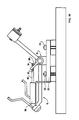
- the manual actuation for the displacement of arms 90, 92, as shown in figures 9A, 9B and 10, can be produced by displacing an actuation lever 320 adapted for rotating about an axis that is different from the axis of rotation of arm 90 and is obtained on support devices 94′, coupled to a bed 2′ in a similar way as that shown in figure 1 for the coupling of support 94 to bed 2.
- Lever 320 has a handle 322 and a substantially flat elongated portion 324. To this portion 324 there are connected a transmission flange 326 and - by means of a junction element 328 - a hydraulic damper 330 with a cylinder 332, a piston axially movable within cylinder 332 and comprising an elongated end 334 protruding from it, and a contact element 336 coupled to said end 334.
- a shaped element, or cam, 338 is secured to support devices 94′.
- Flange 326 also shown in figure 10, has a bent end 340 and limit stop elements 342 and 344, parallel to end 340, adapted for cooperating with diametrally opposite areas of the cylindrical surface of portion 136 of arm 90.
- Figure 9A schematically shows a bench for manual actuation wherein there are shown just bed 2′, support devices 94′, rotary arm 90 with actuation lever 320 and protection structure 20′.
- the asymmetric arrangement of bed 2′ and protection structure 20′ differs from that of the corresponding parts 2 and 20 in figure 1; this is due to the operator's need to reach one side of the bench for operating.
- Arm 90 is shown in figure 9A in a rest position, with the sensing means placed at the farthest distance from the workpiece; this distance is defined by the cooperation between the second reference abutment element 148 fixed to arm 90 and limit stop cap 150.
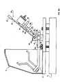
- limit stop element 344 contacts portion 136 of arm 90, forcing the whole arm to rotate in the same direction. From the moment in which contact element 336 contacts the surface of cam 338 the movement of lever 320 and that of arm 90 are dampened. Manually operated lever 320 continues its stroke until bent end 340 of flange 326 contacts a limit stop consisting in a surface portion of support devices 94′ (figure 9B).
- lever 320 In order to withdraw the gauges away from the workpiece, lever 320 is actuated so as to rotate in a counterclockwise direction (again reference should be made to figures 9A and 9B) and limit stop element 342 urges the entire arm 90 to rotate in the same direction, in order to return to the position shown in figure 9A.
- Figures 11 and 12 show an embodiment of a bench gauge according to the present invention for checking a workpiece 42 in rotation.
- a rest device 440 is shown in both figures 11 and 12, whereas a second rest device 410 is only shown in figure 12.
- Device 440 has a support member 444, with a coupling portion 468 fixed to bed 2, a central body 470 and a support part 472, all these parts being similar to corresponding parts of device 44.
- Element 446 comprises a support part 450 and a circular element 452 adapted for freely rotating, with respect to part 450, about an axis defined by a pin 402 connected to part 450 in a way not shown in the figure.
- a first pulley 404 is connected to circular element 452 so as to rotate together and coaxially with it.
- Element 448 comprises a second support part 442 and a second circular element 454 for freely rotating with respect to part 442 about an axis defined by a pin 406 coupled to part 442 in a way not shown in the drawing.
- the circular elements 452, 454 define two relevant cylindrical surfaces lying opposite to each other, which are adapted for simultaneously contacting areas of a same cylindrical portion of the surface of workpiece 42 in such a way as to determine - with the cooperation of the second rest device 410 - the correct positioning of the workpiece 42.
- the position of elements 446, 448 is furthermore adjustable (in a way not shown in the drawings, similar to the one for elements 46, 48 in figure 1) to keep fixed the position of the workpiece axis as the nominal dimensions of the different sections of the rest surfaces of the workpieces vary.
- the second rest device 410 (visible in figure 12 only) comprises a second support member 412 that is substantially similar to member 444 and two second reference elements 414, 416, both substantially similar to element 448, arranged and adjusted in a symmetric way with respect to the axis of workpiece 42, so as to define - together with device 440 - the correct positioning of said workpiece 42.
- Two vertical support elements 420, 422 are rigidly connected to section 468 of member 444 and to a corresponding part of member 412, and each of them comprises a pair of longitudinal parallel flat bars 424, 426, respectively.
- Two bearings - not shown in the figures - are connected in a vertically adjustable way to said vertical support elements 420, 422, respectively, by means of junction elements 436, 438 locked by bolts 456 that pass through holes in elements 436, 438 and the opening formed between the pairs of flat bars 424, 426, and are suitably locked.
- a shaft 458 is supported by the bearings and so lies at one side of bed 2, parallel to bars 4, 6, 8 and 10, free to rotate about its axis.
- a second and a third pulley 460, 462 are coaxial and rigidly fixed to shaft 458 and adapted to rotate together with it.
- the first pulley 404 and the second pulley 460 are substantially coplanar and a belt 464 cooperates with said first and second pulleys in order to transmit to the first (404) the motion of the second (460).
- Actuation means comprise an electric motor 476 (shown in figure 12) that is supported by a support element 478 fixed to bed 2 by means of bolts in the way shown for clamping the other elements of the bench.
- a spindle 480 coming out of motor 476 carries a fourth pulley 482, that is substantially coplanar to said third pulley 462, and is connected to it by means of a second belt 484.
- the rotation commanded by motor 476 to the fourth pulley 482 is so transmitted to the third pulley 462 (by means of belt 484), to the second pulley 460 (by means of the rotation of shaft 458), to the first pulley 404 (by means of belt 464) and to workpiece 42 (by means of circular element 452).
- the adjustment of elements 446, 448 causes, among the other things, transversal displacements of circular element 452 and of its associated pulley 404; in order to keep the tension of belt 464 constant, the position of the second pulley 460 is consequently set, by adjusting the vertical position of shaft 458, i.e. of the bearings on support elements 420, 422.
- the position of the fourth pulley 482, or that of motor 476, is also set (in a way not shown in the drawing) by effecting transversal adjustments, in order to keep the tension of the second belt 484 substantially constant.
- FIG. 1 Another embodiment - not shown in the figures - of the apparatus according to the invention, provides for a structure quite similar to that shown in figures 1 and 2, with fixed rest devices 40, and enables to check the workpiece 42 during its rotation.
- the support and protection means comprise additional support members with two oppositely arranged centres, which are sustained by elements fixed to the bed 2 in the way repeatedly described hereinbefore (for example like devices 40 in figures 1 and 2) and are longitudinally adjustable along guides 16, 18. These centres are aligned to define an axis and can rotate about said axis; a motor is coupled to one of said centres, whereas the other centre (“dead centre”) is free to rotate "idle”.
- the loading of a workpiece 42 to be checked in said apparatus occurs first on the reference devices 40; then the dead centre is brought to contact an end of the workpiece 42 and urges the other end of said workpiece against the other centre in such a way that the axis defined by the centres and the geometrical axis of the workpiece 42 coincide and the workpiece 42 is slightly raised and remains supported by the centres only; then the motor is actuated so as to provide the workpiece rotation.
- the workpiece 42 can be pushed by the dead centre towards the other centre without having to approach the stationary workpiece from both sides. This possibility is provided as there are no sensing means coupled to the workpiece rest devices during the workpiece loading phase, and consequently during said phase the sensing means are not subjected to possible slidings and/or damages.
Landscapes
- Physics & Mathematics (AREA)
- General Physics & Mathematics (AREA)
- Engineering & Computer Science (AREA)
- Mechanical Engineering (AREA)
- A Measuring Device Byusing Mechanical Method (AREA)
- Jigs For Machine Tools (AREA)
Abstract
Description
- The present application is copending with European patent application EP-A-0340272, of the same applicant and having the same priority date, which claims subject matter described in this application. In particular, EP-A-0340272 claims an apparatus for checking workpieces featuring a particular arrangement and coupling between support means supporting the workpiece, a counterbalanced support structure, rotatable about a horizontal axis and including a frame, and gauges fixed to the frame and movable with the support structure to be moved in and out of a measuring position, for going into cooperation with the workpiece, in a direction essentially horizontally tangential to the workpiece.
- The invention relates to an apparatus for checking dimensions of workpieces, with a support structure; reference and support means, coupled to the support structure, for supporting and positioning the workpiece to be checked; a main support frame carried by the support structure; an elongate additional support frame carried by the main support frame; coupling means for coupling the main support frame to the support structure and the additional support frame to the main support frame, the coupling means including a coupling device coupling the additional support frame to the main support frame, substantially at a single zone of the additional support frame; and measuring means including first measuring means fixed to the main support frame and second measuring means secured along the additional support frame, the second measuring means including a plurality of measuring units for providing corresponding measurement signals to be processed for performing combined measurements.
-
- U.S. patent US-A-4233744 to Possati relates to a bench gauge including a support structure carrying a nosepiece ensuring centering and providing a mechanical reference for a workpiece to be checked. A support frame consisting of a plate with three guide slots is coupled to the support structure through three connection elements having a flexible section and arranged at spaced apart locations, in order to reduce the transmission to the plate of stresses and deformations originated in the support structure.
The plate carries a plurality of measuring heads, each of which is coupled to the plate by a plurality of spaced apart connection screws passing through one of the slots. The bench gauge is adapted for checking, statically or dynamically, inside diameters, outside diameters and other characteristics, in particular by combining the signals of different measuring heads.
In this known bench gauge, due to the size and arrangement of the plate and its coupling to the support structure, and also in view of the possibly high number of heads carried by the plate and of their coupling to the plate, the plate is still subject to considerable forces and deformations that can detrimentally affect the accuracy and repeatability of the gauge, in particular as far as combined measurements are concerned. - French patent FR-A-1507371 discloses a modular apparatus for checking features of workpieces, in particular linear dimensions of workpieces having rotational symmetry. The modular components of the apparatus include base plates with slots for positioning and locking other components, among which rest devices for defining the position of the workpiece to be checked, supports and slides for carrying gauges and/or for carrying frames adjustably supporting one or more gauges. According to a particular embodiment, a base plate carries two vee blocks for supporting the workpiece and a cylindrical rod for supporting several gauging heads, adjustable along the rod. The rod is secured to the base plate, through two supports coupled to the ends of the rod and to spaced apart zones at a side of the base plate.
According to another embodiment, a base plate carries a horizontal slide for displacing the workpiece to a measurement position and first and second measuring means carried by corresponding supports. In particular, a vertical rod coupled to the base plate carries the first measuring means and the second measuring means are carried by an elongate frame slidably coupled to the vertical rod through a coupling element. The second measuring means consist of a plurality of measuring devices for performing combined measurements. These measuring devices are simultaneously displaced into cooperation with the workpiece by causing the elongate frame to vertically slide with respect to the vertical rod. - U.S. patent US-A-3905116 relates to an apparatus for measuring crankshafts, including a base, a tailstock and a headstock secured to the base for supporting the crankshaft at its ends, and a carriage mounted on rails parallel to the axis of the crankshaft. A measuring system, including a scale and a digital readout, provides a signal responsive to the position of the carriage relative to a base point. The carriage carries, through two trunnion bearings, a probe including a slidable shaft having at one end a tip for subsequently contacting different surfaces of the crankshaft, for determining, by means of the measuring system, axial locations and distances of the crankshaft surfaces.
- U.S. patent US-A-3011780 relates to a universal gauging device comprising a bed carrying support and reference means, including an adjustable finger and an adjustable stop member for locating the workpiece to be measured. The measurements are performed by means of two dial gauges carried by distinct and spaced apart mounting devices, which are coupled to the bed and permit adjustment of the positions of the dial gauges.
- The invention is intended to overcome the drawbacks of the prior art, by permitting the obtainment of an apparatus in which measuring means - in particular measuring means providing signals adapted to be processed for performing combined measurements - are carried by a support frame that is not subject to substantial stresses and deformations causing modification of the mutual arrangement of the measuring means.
According to the invention, an apparatus for checking dimensions of workpieces comprises a support structure; reference and support means coupled to the support structure for supporting and positioning the workpiece to be checked; a main support frame carried by the support structure; an elongate additional support frame carried by the main support frame; coupling means for coupling the main support frame to the support structure and the additional support frame to the main support frame, the coupling means including a coupling device coupling the additional support frame to the main support frame, substantially at a single zone of the additional support frame; and measuring means including first measuring means (170) fixed to the main support frame and second measuring means secured along the additional support frame, the second measuring means including a plurality of measuring units for providing corresponding measurement signals to be processed for performing combined measurements. The coupling device fixes the additional support frame, at a substantially intermediate zone, to the main support frame, for limiting the occurrence of external forces applied to the additional support frame substantially at said single, intermediate zone and preventing thereby substantial deformations of the additional support frame, and the coupling means comprise movable elements coupled to the support structure to define an axis for the rotation of the main support frame with respect to the support structure, to displace the measuring means into cooperation with the workpiece.
The effects and advantages offered by the invention are that the measuring devices to be used for performing combined measurements are not subjected to substantial, undesired mutual displacements and therefore the accuracy and repeatability of the combined measurements are very good. The support frame can be very light and compact and this is of advantage for several reasons, e.g. for increasing the availability of space, for rendering simpler the construction of an apparatus in which the support frame has to be movable, etc. Moreover, the support structure, the kinematic elements and the control means of the apparatus need not be of high precision and consequently the manufacturing costs decrease. - Specific embodiments of the invention are now described in detail with reference to the enclosed tables of drawings, given by way of example and not of limitation, in which:
- figure 1 is a transversal partially sectional view of a bench gauge according to the present invention with some parts furtherly sectioned in order to evidence some details;
- figure 2 is a longitudinal sectional view of the bench gauge shown in figure 1 along the path II-II in figure 1, with the omission of some elements and others placed in a different position with respect to figure 1, for clarity reasons;
- figure 3 is a perspective view of a detail of the bench gauge shown in figures 1 and 2, with a different scale as compared to that of figures 1 and 2;
- figures 4A and 4B are respectively a front view with some details in a sectional view and a longitudinal sectional view along the path B-B in figure 4A, of a second detail of the bench gauge shown in figure 1, with a different scale as compared to that of figure 1;
- figure 5 is a sectional view of a third detail of the bench gauge shown in figure 2, along the path V-V in figure 2;
- figure 6 shows a fourth detail of the bench gauge shown in figure 2, along the path VI-VI in figure 2;
- figure 7 is a perspective view of a detail of the bench gauge of figures 1 and 2, with a different scale from that of figures 1 and 2;
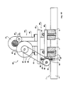
- figure 8 is a side view of a detail of a bench gauge according to the invention;
- figures 9A and 9B are side views of some elements of a bench gauge according to another embodiment of the invention, at two different moments of operation;
- figure 10 is a sectional view of a detail of a part shown in figures 9A and 9B, along the section X-X in figure 9B;
- figure 11 is a side view of some elements of a bench gauge according to a third embodiment of the invention; and
- figure 12 is a plan view of some elements of a bench gauge according to said third embodiment of the invention.
- The bench gauge shown in figures 1 and 2 comprises a support structure including a base, or bed 2 (also shown in figure 3), with two pairs of longitudinal bars having a
rectangular cross-section crosspieces Longitudinal openings parallel bars - A protection structure 20 (also shown in figures 4A and 4B) comprises two
halfshells flat bars -
Structure 20 is positioned onbed 2 in such a way that theflat bars bars flat bars holes 30 and 32 (just those offlat bar 26 are shown in figure 4A) formed in such positions so as to arrange themselves in correspondence toopenings Structure 20 is secured tobed 2 by means of bolts (as an example just one is shown in figure 4A) consisting ofscrews 34 with a hexagonal head inserted in openings 16 (18) and in through holes 30 (32), and ofnuts 36 that are fastened to said screws so contacting against the upper surface offlat bars screws 34 are thus urged against the bottom surface of bars 4, 6 (8, 10). - Reference and support means comprise two rest devices 40 (only one is shown in figure 1), for supporting a
workpiece 42 to be checked with its geometrical axis horizontally arranged. Therest devices 40 comprisesupport members 44 arranged onbase 2 according to mutually parallel transversal directions and pairs ofreference elements members 44. The reference elements, and more specificallyelement 46, have afirst portion 50 with tworest surfaces element 48 and about an axis defined byassociated support member 44, in such a way so as to define V-shaped rests forworkpiece 42 with different sloping surfaces if the sides of the V are the pairs ofsurfaces - Reference element 46 (just like element 48) further comprises a clamping portion with two
parallel blocks first portion 50 and with a free end, that define anopening 60; the width of saidopening 60 is limited, near the free ends ofblocks welding spots portion 50 opposite to restsurfaces -
Support member 44 basically comprises three parts: acoupling portion 68, acentral body 70 and asupport part 72. Thecoupling portion 68, shown in figure 2 only, comprises two through holes for the coupling of thewhole rest device 40 tobed 2, and more specifically to the pairs oflongitudinal bars protection structure 20.Portion 68 ofmember 44 is fully identical to apart 98 shown in figures 1 and 2 (and pertaining to another device of the bench gauge) that will be described hereinafter and is coupled tobed 2 in the same way as this one. It should be realized that this particular method of coupling enables a continuous adjustment of the longitudinal position of therest devices 40. -
Support part 72 comprises two elongated portions with an "L"shaped section central body 70 in such a way that the bases of the Ls face each other so as to form atransversal seat 78. The fixing of each ofreference elements coupling portion 68 ofsupport member 44 is made in the following way: element 46 (48) is placed onbody 70 so that overhang 66 is inserted inseat 78 andblocks portions portions seat 78 and is inserted in opening 60 of element 46 (and is held there thanks towelding spots nut 82 locked at the end of screw 80 urges against surfaces ofblocks sections seat 78 so bring about the locking ofelement 46 to supportmember 44. In an entirelysimilar way element 48 is also clamped to supportmember 44. - The possibility of adjusting the mutual position of the
reference elements rest devices 40 to ensure a correct positioning ofworkpieces 42 to be checked as the nominal dimensions of the different workpieces (and/or of different sections of a same workpiece) vary - within a broad range -, while maintaining substantially constant the position of the workpiece axis. - Coupling means comprise another
support structure 88 includingrotary arms bed 2. As thearms supports arm 90 and associatedsupport 94 only, as shown in figures 1 and 2. -
Support 94 comprises aportion 98 for coupling tobed 2, afulcrum section 100 that defines, together with the corresponding fulcrum section ofsupport 96, an axis of rotation forarms entire support structure 88, and alimit stop part 102. -
Portion 98 has two throughholes openings support 94 rests onbed 2. -
Support 94 is secured tobed 2 by means of bolts consisting inscrews openings holes nuts portion 98; the heads ofscrews bars - The
fulcrum section 100 comprises tworectangular plates portion 98, so as to arrange themselves in a vertical and parallel way with respect to each other.Plates holes stop part 102, at their edges opposite the above mentioned edges. Thelatter part 102 substantially comprises two rectangular reciprocally slopingportions plates reference abutment 128. -
Rotary arm 90 comprises: a firstelongated portion 132, a second elongated portion 134 - angularly coupled to the first - a thirdelongated portion 136 with a circular cross-section, an annular portion 138 - that connects said second and thirdelongated portions portions annular portion 138 comprising ahole 140 with an axis arranged transversally with respect toelongated portions counterweight end portion 142 connected to the thirdelongated portion 136. -
Arm 90 is inserted betweenplates fulcrum section 100 ofsupport 94, in such a way that the transversal axis ofhole 140 is aligned with the above mentioned axis of rotation. - A
cylindrical pin 144 is inserted throughhole 140 ofportion 138 andholes plates arm 90 to support 94 in such a way that the latter may rotate about said axis of rotation. - A first
reference abutment element 146 is fixed to the secondelongated portion 134 and is adapted for cooperating withreference abutment 128 for limiting the rotation ofarm 90 in a clockwise direction (as shown in figure 1). A secondreference abutment element 148 is coupled toportion 134, opposite toelement 146, and alimit stop cap 150 is coupled tonut 112;element 148 and limitstop cap 150 cooperate for limiting the rotation ofarm 90 in a direction opposite to the previously mentioned one. - The
first portion 132 ofarm 90 has a throughhole 152. - The
support structure 88 also comprises a main supportingframe 154, shown in figure 2, with twobars segments longitudinal opening 164 that forms a guide.Frame 154 is coupled torotary arms 90, 92: more specifically it is fixed to the firstelongated portions 132 by means ofscrews 166, that are inserted throughholes 152 andopening 164 and then locked bynuts 168, according to the same method of clamping the various parts of the bench gauge tobed 2. - Sensing or measuring means comprise gauges 170 of the "snap" type (only one of them is shown in figure 1) with an
integral element 172 that has acoupling portion 174, twoshaped end portions feelers workpiece 42, and two portions with athinner section thinner section end portions coupling portion 174. Resilient means 188 adapted for urging theend portions end portions end portions Electric cables 278, not shown in figures 1 and 2 but in figure 7 only, transmit signals from the transducer means 192 to connector blocks (not shown) and to processing anddisplay units 194. - A hole in
portion 174 allows the coupling ofgauge 170 to frame 154 by means of ascrew 198 that passes throughopening 164 and the aforementioned hole and is locked by anut 200. - An
additional support frame 210 comprises twobars 212, 214 - that are similar tobars segments opening 220 being defined betweenbars spacer block 222 arranged at the intermediate zone ofsupport frame 210 has a throughhole 224 for housing ascrew 226; moreover the latter is inserted throughopenings support frame 210 tomain frame 154. Second sensing or measuring means, or gauges, 230 similar to gauge 170 are fixed to supportframe 210 according to the same coupling method used forcoupling gauge 170 toframe 154. However, while the transducer means 192 ofgauge 170 can comprise a single transducer, eachgauge 230 for diameter checking normally comprises two transducers. Moreover, further gauges for determining axial dimensions can be fixed to supportframe 210. - Normally the
gauges 170 carried bymain frame 154 are used for performing single relevant measurements, whilegauges 230 carried byframe 210 are used for carrying out combined measurements (by processing the signals of gauges 230). - The
counterweight end portion 142 has a substantially parallelepided shape and is adapted for balancing the weight of the sensing means 170, 230 coupled toframes rotary arm 90. - As the number of
gauges 170 onframe 154 can vary and/or depending on the presence or not offrame 210 withrelevant gauges 230, it is possible to add to thecounterweight end portion 142additional elements 232, coupled by means of ascrew 234 that crossesportion 142 andelements 232 by passing through holes that are not shown in figure 1, and is locked by anut 236. In this way it is possible to keep substantially constant the force required to makearms gauges workpiece 42 to be checked. - The shape and the positioning of
rest devices 40 and supports 94, 96 ofrotary arms support structure 88 and the axis of theworkpiece 42 to be checked lie, the first below the second, in a vertical geometrical plane coincident with the viewing plane of figure 2. - This arrangement enables to achieve a considerable reduction in the overall dimensions of the whole apparatus and simplifies the (manual or automatic) loading of
workpiece 42 onrest devices 40 and at the same time protects the sensing means 170, 230, that are conveniently arranged apart from these devices. - The particular coupling of
gauges 170 to frame 154 by means of just one bolt further prevents each of the sensing means 170 from being affected by possible plays due to inexact alignment of the axes of rotation ofarms additional frame 210 in turn coupled by just one bolt to frame 154: possible misalignments among a plurality ofgauges 230 coupled to supportframe 210 due, for example, to clearances in the rotations ofarms frame 210 can also be connected to frame 154 by means of two bolts positioned sufficiently close together, instead of one, in order to obtain the same result.
It is pointed out thatframe 210 does not carry reference devices, such as Vee devices, for cooperating with theworkpiece 42 and that the forces between the feelers ofgauges 230 andworkpiece 42 are very small.Support frame 210 can be much longer than that shown in figures 2 and 5, but it and gauges 230 can be of very limited weight, therefore deformations of theframe 210 due to its own weight and to the weight ofgauges 230 are very small, also in view of the coupling offrame 210 at an intermediate zone. Therefore, the external forces and the stresses acting on thesupport frame 210 only consist, basically, of the forces and stresses occurring at the limited zone next to screw 226 andspacer block 222. - Guide elements or
bumpers bed 2 by means of bolts, in a quite similar way as for the other elements described up to now - for example likesupport 94 in the case ofarm 90. Theguide elements holes 244 in the guide elements (just the one referring toelement 242 is shown in a sectional view in figure 2) can be used for the initial adjustment ofrest devices 40. In this case pointedreference screws 246 are screwed down through saidholes 244 with their points opposite to each other so as to carry a master piece in the correct position and suitably adjustdevices 40 by setting the position ofreference elements support member 44. Once the correct arrangement ofdevices 40 has been reached, pointedscrews 246 are unscrewed and theworkpieces 42 to be checked are directly placed on said devices. - Furthermore there can be foreseen an
additional protection element 250 coupled tobed 2 in a similar way as the others (i.e. locked to the pairs ofbars portion 98 shown in figure 1); saidelement 250 is shown in figure 6 and comprises a substantially flat and V-shapedportion 252 adapted to be arranged parallel to restdevices 40. The function ofelement 250 is that of supportingworkpiece 42 in the event that the positioning of the rest devices 40 (more specifically of thereference elements 46, 48) is inexact, in order to prevent the workpiece 42 from colliding against other parts of the bench gauge during, for example, the automatic loading operation. - Figure 7 schematically shows some details - that are not shown in the other figures of the bench gauge described up to now. A
plate 260 withholes 272 is secured to and belowframe 154, by means of twobridge elements bolts - Locking
elements 270 made of plastic comprise a cylindrical end (not visible in the figure) adapted for insertion in arelevant hole 272 ofplate 260, and a substantially annular portion 274 with aslit 276. The lockingelements 270 are inserted inholes 272 in correspondence to the position of sensing means 170, 230 coupled to main frame 154 (or to additional frame 210). In figure 7, for simplicity's sake, the sensing means are not explicitly shown, but just indicated by associated locking screws 198. Eachcable 278 coming out of transducer means 192 of agauge 170 is inserted throughslit 276, in the associated lockingelement 270 and in all theother elements 270 onplate 260 placed between the relevant gauge andarm 92. Allcables 278 so aligned alongplate 260 are inserted in araceway 280 fixed toarm 92 and extending up to pin 144, i.e. the axis of rotation ofarm 92. In thisway cables 278 can integrally rotate with the movable part of the support structure (90, 92, 154) without being subject to unwanted torsions. - It should be realized that
cables 278 can be led to connector blocks (as hereinbefore mentioned) and that said blocks can also be coupled tobed 2 by means of suitable supports comprising a coupling section that is under all aspects similar toportion 98 shown in figure 1 and coupled in the same way. - The rotation of
support structure 88, and consequently the displacement of the sensing means 170, 230 movable with it from a rest position to a working one, in cooperation withworkpiece 42 to be checked, can occur in an automatic or manual way. In the first instance - schematically shown in figure 8 - there are foreseen automatic actuation means comprising a hydraulic actuation system with acylinder 300 and a piston with anend 302 that engages, by means of limit stopelements lever 304 rigidly coupled toarm 90 and adapted for rotating about the same axis of rotation of said arm. -
Cylinder 300 is coupled, in a way not shown in the figure, to a support 306, in turn secured tobed 2 by means ofbolts 308, 310, in a way quite similar to that used forportion 98 shown in figure 1. - The automatic actuation of the rotation motion can occur in a similar way by using pneumatic means.
- Logic circuits can moreover be coupled to
bed 2 by means of supports that are coupled tobed 2 in the way hereinabove repeatedly described (seeportion 98 in figure 1). - The manual actuation for the displacement of
arms actuation lever 320 adapted for rotating about an axis that is different from the axis of rotation ofarm 90 and is obtained onsupport devices 94′, coupled to abed 2′ in a similar way as that shown in figure 1 for the coupling ofsupport 94 tobed 2. -
Lever 320 has ahandle 322 and a substantially flatelongated portion 324. To thisportion 324 there are connected atransmission flange 326 and - by means of a junction element 328 - ahydraulic damper 330 with acylinder 332, a piston axially movable withincylinder 332 and comprising anelongated end 334 protruding from it, and acontact element 336 coupled to saidend 334. - A shaped element, or cam, 338 is secured to support
devices 94′. -
Flange 326, also shown in figure 10, has abent end 340 and limit stopelements portion 136 ofarm 90. - Figure 9A schematically shows a bench for manual actuation wherein there are shown just
bed 2′,support devices 94′,rotary arm 90 withactuation lever 320 andprotection structure 20′. The asymmetric arrangement ofbed 2′ andprotection structure 20′ differs from that of thecorresponding parts Arm 90 is shown in figure 9A in a rest position, with the sensing means placed at the farthest distance from the workpiece; this distance is defined by the cooperation between the secondreference abutment element 148 fixed toarm 90 andlimit stop cap 150. - By making
lever 320 rotate in a clockwise direction (with reference to figure 9A)limit stop element 344contacts portion 136 ofarm 90, forcing the whole arm to rotate in the same direction. From the moment in whichcontact element 336 contacts the surface ofcam 338 the movement oflever 320 and that ofarm 90 are dampened. Manually operatedlever 320 continues its stroke untilbent end 340 offlange 326 contacts a limit stop consisting in a surface portion ofsupport devices 94′ (figure 9B). - The rotation of
arm 90 continues, dampened bydamper 330, until contact betweenreference abutment element 146 and reference abutment 128 (figure 9B) occurs, said contact defining the correct position of the sensing means or gauges 170, 230 on theworkpiece 42 to be checked. - In order to withdraw the gauges away from the workpiece,
lever 320 is actuated so as to rotate in a counterclockwise direction (again reference should be made to figures 9A and 9B) andlimit stop element 342 urges theentire arm 90 to rotate in the same direction, in order to return to the position shown in figure 9A. - Figures 11 and 12 show an embodiment of a bench gauge according to the present invention for checking a
workpiece 42 in rotation. - The structure of the bench gauge is similar to that described hereinbefore, with the sole substantial difference in the construction of the rest devices that, in this case, have to drive
workpiece 42 to accomplish the required rotation and/or enable this rotation. Arest device 440 is shown in both figures 11 and 12, whereas asecond rest device 410 is only shown in figure 12.Device 440 has asupport member 444, with acoupling portion 468 fixed tobed 2, acentral body 470 and asupport part 472, all these parts being similar to corresponding parts ofdevice 44. - Two
different reference elements part 472 in the same way aselements part 72 of member 44 (see figure 1 and its pertaining description). -
Element 446 comprises asupport part 450 and acircular element 452 adapted for freely rotating, with respect topart 450, about an axis defined by apin 402 connected topart 450 in a way not shown in the figure. Afirst pulley 404 is connected tocircular element 452 so as to rotate together and coaxially with it. -
Element 448 comprises asecond support part 442 and a secondcircular element 454 for freely rotating with respect topart 442 about an axis defined by apin 406 coupled topart 442 in a way not shown in the drawing. Thecircular elements workpiece 42 in such a way as to determine - with the cooperation of the second rest device 410 - the correct positioning of theworkpiece 42. The position ofelements elements - The second rest device 410 (visible in figure 12 only) comprises a
second support member 412 that is substantially similar tomember 444 and twosecond reference elements element 448, arranged and adjusted in a symmetric way with respect to the axis ofworkpiece 42, so as to define - together with device 440 - the correct positioning of saidworkpiece 42. - Two
vertical support elements section 468 ofmember 444 and to a corresponding part ofmember 412, and each of them comprises a pair of longitudinal parallelflat bars vertical support elements junction elements bolts 456 that pass through holes inelements flat bars shaft 458 is supported by the bearings and so lies at one side ofbed 2, parallel tobars third pulley shaft 458 and adapted to rotate together with it. - The
first pulley 404 and thesecond pulley 460 are substantially coplanar and abelt 464 cooperates with said first and second pulleys in order to transmit to the first (404) the motion of the second (460). Actuation means comprise an electric motor 476 (shown in figure 12) that is supported by asupport element 478 fixed tobed 2 by means of bolts in the way shown for clamping the other elements of the bench. Aspindle 480 coming out ofmotor 476 carries afourth pulley 482, that is substantially coplanar to saidthird pulley 462, and is connected to it by means of asecond belt 484. The rotation commanded bymotor 476 to thefourth pulley 482 is so transmitted to the third pulley 462 (by means of belt 484), to the second pulley 460 (by means of the rotation of shaft 458), to the first pulley 404 (by means of belt 464) and to workpiece 42 (by means of circular element 452). - As the nominal dimensions of the rest section of
workpiece 42 vary, the adjustment ofelements circular element 452 and of its associatedpulley 404; in order to keep the tension ofbelt 464 constant, the position of thesecond pulley 460 is consequently set, by adjusting the vertical position ofshaft 458, i.e. of the bearings onsupport elements - The position of the
fourth pulley 482, or that ofmotor 476, is also set (in a way not shown in the drawing) by effecting transversal adjustments, in order to keep the tension of thesecond belt 484 substantially constant. - Another embodiment - not shown in the figures - of the apparatus according to the invention, provides for a structure quite similar to that shown in figures 1 and 2, with fixed
rest devices 40, and enables to check theworkpiece 42 during its rotation. In such embodiment the support and protection means comprise additional support members with two oppositely arranged centres, which are sustained by elements fixed to thebed 2 in the way repeatedly described hereinbefore (for example likedevices 40 in figures 1 and 2) and are longitudinally adjustable along guides 16, 18. These centres are aligned to define an axis and can rotate about said axis; a motor is coupled to one of said centres, whereas the other centre ("dead centre") is free to rotate "idle". - The loading of a
workpiece 42 to be checked in said apparatus occurs first on thereference devices 40; then the dead centre is brought to contact an end of theworkpiece 42 and urges the other end of said workpiece against the other centre in such a way that the axis defined by the centres and the geometrical axis of theworkpiece 42 coincide and theworkpiece 42 is slightly raised and remains supported by the centres only; then the motor is actuated so as to provide the workpiece rotation. - It should be realized that the
workpiece 42 can be pushed by the dead centre towards the other centre without having to approach the stationary workpiece from both sides. This possibility is provided as there are no sensing means coupled to the workpiece rest devices during the workpiece loading phase, and consequently during said phase the sensing means are not subjected to possible slidings and/or damages.
Claims (4)
- Apparatus for checking dimensions of workpieces (42), with a support structure (2); reference and support means (40) coupled to the support structure (2), for supporting and positioning the workpiece to be checked (42); a main support frame (154) carried by the support structure (2); an elongate additional support frame (210) carried by the main support frame (154); coupling means (88) for coupling the main support frame (154) to the support structure (2) and the additional support frame (210) to the main support frame (154), the coupling means (88) including a coupling device (222, 226, 228) coupling the additional support frame (210) to the main support frame (154), substantially at a single zone of the additional support frame (210); and measuring means including first measuring means (170) fixed to the main support frame (154) and second measuring means secured along the additional support frame (210), the second measuring means including a plurality of measuring units (230) for providing corresponding measurement signals to be processed for performing combined measurements, characterized in that said coupling device (88) fixes the additional support frame (210), at a substantially intermediate zone, to the main support frame (154), for limiting the occurrence of external forces applied to the additional support frame (210) substantially at said single, intermediate zone and preventing thereby substantial deformations of the additional support frame (210), and in that said coupling means (88) comprise movable elements (90, 92) coupled to the support structure (2) to define an axis for the rotation of the main support frame (154) with respect to the support structure (2), to displace the measuring means into cooperation with the workpiece (42).
- An apparatus according to claim 1, wherein the support structure (2) and the coupling means (88) comprise reference means (128, 146, 148, 150) for defining a mutual rest position and a mutual operative position between said support frames (154, 210) and the support structure (2).
- An apparatus according to claim 1 or claim 2, wherein said main support frame and additional support frame (154; 210) are elongate along a same direction, and said first measuring means (170) and said measuring units (230) are adjustable along said direction, respectively on the main support frame (154) and additional support frame (210).
- An apparatus according to claim 3, wherein each of said first measuring means (170) and measuring units (230) is secured to the relevant frame (154; 210) by a single bolt (198, 200).
Applications Claiming Priority (2)
| Application Number | Priority Date | Filing Date | Title |
|---|---|---|---|
| IT8703683A IT1213718B (en) | 1987-11-09 | 1987-11-09 | APPARATUS FOR CHECKING CHARACTERISTICS OF PIECES WITH ROTATION SYMMETRY |
| IT368387 | 1987-11-09 |
Publications (2)
| Publication Number | Publication Date |
|---|---|
| EP0340271A1 EP0340271A1 (en) | 1989-11-08 |
| EP0340271B1 true EP0340271B1 (en) | 1993-02-03 |
Family
ID=11111367
Family Applications (4)
| Application Number | Title | Priority Date | Filing Date |
|---|---|---|---|
| EP88830467A Pending EP0318436A1 (en) | 1987-11-09 | 1988-11-03 | Apparatus for checking dimensions of workpieces |
| EP88909605A Expired - Lifetime EP0340271B1 (en) | 1987-11-09 | 1988-11-03 | Apparatus for checking dimensions of workpieces |
| EP88830468A Pending EP0318437A1 (en) | 1987-11-09 | 1988-11-03 | Apparatus for checking dimensions of workpieces |
| EP88909606A Expired - Lifetime EP0340272B1 (en) | 1987-11-09 | 1988-11-03 | Apparatus for checking dimensions of workpieces |
Family Applications Before (1)
| Application Number | Title | Priority Date | Filing Date |
|---|---|---|---|
| EP88830467A Pending EP0318436A1 (en) | 1987-11-09 | 1988-11-03 | Apparatus for checking dimensions of workpieces |
Family Applications After (2)
| Application Number | Title | Priority Date | Filing Date |
|---|---|---|---|
| EP88830468A Pending EP0318437A1 (en) | 1987-11-09 | 1988-11-03 | Apparatus for checking dimensions of workpieces |
| EP88909606A Expired - Lifetime EP0340272B1 (en) | 1987-11-09 | 1988-11-03 | Apparatus for checking dimensions of workpieces |
Country Status (9)
| Country | Link |
|---|---|
| US (2) | US5086569A (en) |
| EP (4) | EP0318436A1 (en) |
| JP (2) | JP2682861B2 (en) |
| KR (2) | KR0122130B1 (en) |
| BR (2) | BR8807286A (en) |
| DE (2) | DE3878225T2 (en) |
| ES (2) | ES2038791T3 (en) |
| IT (1) | IT1213718B (en) |
| WO (2) | WO1989004455A1 (en) |
Families Citing this family (29)
| Publication number | Priority date | Publication date | Assignee | Title |
|---|---|---|---|---|
| IT1213718B (en) * | 1987-11-09 | 1989-12-29 | Marposs Spa | APPARATUS FOR CHECKING CHARACTERISTICS OF PIECES WITH ROTATION SYMMETRY |
| IT1242648B (en) * | 1990-05-30 | 1994-05-16 | Marposs Spa | METHOD FOR DYNAMIC DIMENSIONAL CONTROL OF MECHANICAL PIECES, AND RELATED APPARATUS. |
| IT1266221B1 (en) * | 1993-01-21 | 1996-12-27 | Marposs Spa | EQUIPMENT FOR THE GEOMETRIC CHECK OF PIECES WITH ROTATION SYMMETRY |
| US5460058A (en) * | 1994-03-02 | 1995-10-24 | Trw Vehicle Safety Systems Inc. | Apparatus and method for inspecting an air bag module |
| DE4420137A1 (en) * | 1994-06-09 | 1995-12-14 | Zeiss Messgeraetebau Gmbh | Measuring device for checking the dimensions of cylindrical workpieces |
| IT1279641B1 (en) | 1995-10-03 | 1997-12-16 | Marposs Spa | APPARATUS FOR CHECKING THE DIAMETER OF CONNECTING ROD PINS IN ORBITAL MOTION |
| DE69608291T2 (en) * | 1995-10-06 | 2001-01-04 | Etamic S.A., Saint-Martin-Des-Entrees | MEASURING AND CONTROL DEVICE FOR MACHINING CYLINDRICAL WORKPIECES |
| US6463669B1 (en) * | 1998-04-15 | 2002-10-15 | Rollomatic S.A. | Apparatus for checking the shape of a part |
| US6298572B1 (en) | 2000-01-10 | 2001-10-09 | Mcauley Brian | Universal holding device for effectuating three dimensional measurement of a part and method of constructing such a holding device |
| ITBO20000012A1 (en) * | 2000-01-18 | 2001-07-18 | Marposs Spa | PIN DIAMETER CONTROL EQUIPMENT. |
| DE20003772U1 (en) * | 2000-03-01 | 2001-07-19 | Prüftechnik Dieter Busch AG, 85737 Ismaning | Adapter for checking the angular alignment of a roller to be precisely stored |
| JP2002168616A (en) * | 2000-11-30 | 2002-06-14 | Fuji Photo Film Co Ltd | Tool for measuring peripheral face shape of roll type article |
| SE0401408D0 (en) * | 2004-06-02 | 2004-06-02 | Astrazeneca Ab | Diameter measuring device |
| JP4923549B2 (en) * | 2005-12-08 | 2012-04-25 | 株式会社ジェイテクト | Mounting structure for sizing equipment |
| CN101598538A (en) * | 2008-06-04 | 2009-12-09 | 鸿富锦精密工业(深圳)有限公司 | Workpiece detecting device |
| US7748134B1 (en) * | 2009-03-09 | 2010-07-06 | Yao-Chung Wang | Measuring device for cylinder |
| DE102009032353A1 (en) | 2009-07-08 | 2011-09-08 | Hommel-Etamic Gmbh | Method for determining the shape of a workpiece |
| DE102009042252B4 (en) | 2009-09-22 | 2014-03-06 | Jenoptik Industrial Metrology Germany Gmbh | measuring device |
| DE102010013069B4 (en) * | 2010-03-26 | 2012-12-06 | Hommel-Etamic Gmbh | measuring device |
| DE102010035147B4 (en) | 2010-08-23 | 2016-07-28 | Jenoptik Industrial Metrology Germany Gmbh | measuring device |
| DE102012018580B4 (en) | 2012-09-20 | 2015-06-11 | Jenoptik Industrial Metrology Germany Gmbh | Measuring device and measuring method for in-process measurement on test specimens during a machining operation on a processing machine, in particular a grinding machine |
| US9897428B2 (en) * | 2014-12-22 | 2018-02-20 | Monte Hieb | Diametral measurement system for evaluation of cylindrical objects, including rock cores |
| CN104964127A (en) * | 2015-05-14 | 2015-10-07 | 广西金达造船有限公司 | Main engine seat structure |
| IT201700088988A1 (en) * | 2017-08-02 | 2019-02-02 | Marposs Spa | EQUIPMENT FOR THE CONTROL OF DIAMETER DIMENSIONS OF A PIN OF ORBITAL MOTION |
| EP3743677B1 (en) * | 2018-01-22 | 2021-04-28 | Reginald Galestien | Method and apparatus for measuring diameters of cylindrical measuring pins |
| KR102352966B1 (en) * | 2019-12-02 | 2022-01-20 | 주식회사 호원 | Apparatus for measuring step of sample |
| CN110925528A (en) * | 2019-12-12 | 2020-03-27 | 徐州市工业设备安装有限责任公司 | Adjusting device for electromechanical device installation |
| CN112664759A (en) * | 2021-01-15 | 2021-04-16 | 李奇 | Agricultural machine field operation intelligent management ware |
| DE102022123873B3 (en) | 2022-09-17 | 2024-03-07 | Schübel GmbH | Testing or measuring device |
Citations (1)
| Publication number | Priority date | Publication date | Assignee | Title |
|---|---|---|---|---|
| EP0340272A1 (en) * | 1987-11-09 | 1989-11-08 | Marposs Societa Per Azioni | Apparatus for checking dimensions of workpieces |
Family Cites Families (23)
| Publication number | Priority date | Publication date | Assignee | Title |
|---|---|---|---|---|
| US1587217A (en) * | 1924-11-12 | 1926-06-01 | Wymangordon Company | Crank-shaft indexing machine |
| US2609609A (en) * | 1946-07-10 | 1952-09-09 | Western Electric Co | Gauge for checking parts of cylindrical articles |
| US2688802A (en) * | 1949-03-01 | 1954-09-14 | Perfect Circle Corp | Machine mounted diameter gauge |
| DE837608C (en) * | 1949-10-18 | 1952-04-28 | Rudolf Westenberger | Device for monitoring and measuring the grinding process on cylindrical grinding machines |
| US2625773A (en) * | 1949-10-20 | 1953-01-20 | Fortuna Werke Spezialmaschinen | Automatic circular grinding machine |
| US2854756A (en) * | 1950-11-04 | 1958-10-07 | Sheffield Corp | Gauging device for checking size or contour |
| US3011780A (en) * | 1958-01-02 | 1961-12-05 | Hanisko Joseph | Universal gauge |
| NL292039A (en) * | 1962-04-27 | |||
| US3281995A (en) * | 1963-12-20 | 1966-11-01 | Farrel Corp | Machine tool |
| GB1093183A (en) * | 1964-05-28 | 1967-11-29 | Rank Precision Ind Ltd | Improvements in or relating to apparatus for testing the diameter of a cylindrical surface |
| US3302920A (en) * | 1964-09-25 | 1967-02-07 | Caterpillar Tractor Co | Apparatus for producing templates |
| FR1507371A (en) * | 1966-11-18 | 1967-12-29 | Bonnet Ets | Improvements in the constitution of devices for simultaneous verification of several dimensions of numerous objects |
| GB1335949A (en) * | 1971-05-28 | 1973-10-31 | Fiat Spa | Apparatus for dimensional testing of nominally cylindrical workpieces |
| US3905116A (en) * | 1973-10-15 | 1975-09-16 | Allis Chalmers | Crankshaft bearing measuring apparatus |
| US4006529A (en) * | 1975-09-08 | 1977-02-08 | Herman Martin A | Check gage for article thickness |
| US4122608A (en) * | 1977-04-22 | 1978-10-31 | Teledyne Industries, Inc. | Tube feeler |
| US4233744A (en) * | 1978-12-01 | 1980-11-18 | Finike Italiana Marposs S.P.A. | Apparatus for the geometrical checking of workpieces having surfaces of rotation |
| AT385121B (en) * | 1982-10-15 | 1988-02-25 | Steyr Daimler Puch Ag | DEVICE FOR MEASURING OR MONITORING THE DIAMETER OF ROD-SHAPED WORKPIECES |
| IT1169180B (en) * | 1983-03-09 | 1987-05-27 | Finike Italiana Marposs | COMPARATOR FOR THE CONTROL OF LINEAR DIMENSIONS OF MECHANICAL PIECES |
| IT1180539B (en) * | 1984-10-15 | 1987-09-23 | Finike Italiana Marposs | HEAD FOR THE CONTROL OF MECHANICAL PARTS DIMENSIONS |
| US4604810A (en) * | 1985-08-29 | 1986-08-12 | The Monarch Machine Tool Company | Post process diameter gage |
| IT1191688B (en) * | 1986-03-20 | 1988-03-23 | Giustina International Spa | CYLINDER GRINDING MACHINE WITH SIGNIFICANT BODIES AND DIMENSIONAL AND SURFACE CONTROL |
| US4914827A (en) * | 1988-12-28 | 1990-04-10 | Gte Valenite Corporation | Protection technique for gage heads |
-
1987
- 1987-11-09 IT IT8703683A patent/IT1213718B/en active
-
1988
- 1988-11-03 ES ES198888909605T patent/ES2038791T3/en not_active Expired - Lifetime
- 1988-11-03 JP JP63508870A patent/JP2682861B2/en not_active Expired - Lifetime
- 1988-11-03 ES ES198888909606T patent/ES2031640T3/en not_active Expired - Lifetime
- 1988-11-03 DE DE8888909605T patent/DE3878225T2/en not_active Expired - Fee Related
- 1988-11-03 EP EP88830467A patent/EP0318436A1/en active Pending
- 1988-11-03 KR KR1019890701297A patent/KR0122130B1/en not_active Expired - Fee Related
- 1988-11-03 BR BR888807286A patent/BR8807286A/en not_active IP Right Cessation
- 1988-11-03 WO PCT/IT1988/000077 patent/WO1989004455A1/en not_active Ceased
- 1988-11-03 EP EP88909605A patent/EP0340271B1/en not_active Expired - Lifetime
- 1988-11-03 JP JP63508871A patent/JP2682862B2/en not_active Expired - Lifetime
- 1988-11-03 WO PCT/IT1988/000078 patent/WO1989004456A1/en not_active Ceased
- 1988-11-03 EP EP88830468A patent/EP0318437A1/en active Pending
- 1988-11-03 BR BR888807301A patent/BR8807301A/en not_active IP Right Cessation
- 1988-11-03 EP EP88909606A patent/EP0340272B1/en not_active Expired - Lifetime
- 1988-11-03 DE DE8888909606T patent/DE3871380D1/en not_active Expired - Lifetime
- 1988-11-03 US US07/381,647 patent/US5086569A/en not_active Expired - Fee Related
- 1988-11-03 KR KR1019890701298A patent/KR0122129B1/en not_active Expired - Fee Related
-
1989
- 1989-06-16 US US07/378,194 patent/US5068974A/en not_active Expired - Fee Related
Patent Citations (1)
| Publication number | Priority date | Publication date | Assignee | Title |
|---|---|---|---|---|
| EP0340272A1 (en) * | 1987-11-09 | 1989-11-08 | Marposs Societa Per Azioni | Apparatus for checking dimensions of workpieces |
Also Published As
| Publication number | Publication date |
|---|---|
| IT1213718B (en) | 1989-12-29 |
| BR8807286A (en) | 1990-03-27 |
| KR890701985A (en) | 1989-12-22 |
| JPH02502124A (en) | 1990-07-12 |
| ES2031640T3 (en) | 1992-12-16 |
| KR890701984A (en) | 1989-12-22 |
| ES2038791T3 (en) | 1993-08-01 |
| DE3878225D1 (en) | 1993-03-18 |
| KR0122130B1 (en) | 1997-11-11 |
| JP2682862B2 (en) | 1997-11-26 |
| JP2682861B2 (en) | 1997-11-26 |
| JPH02502125A (en) | 1990-07-12 |
| EP0340271A1 (en) | 1989-11-08 |
| WO1989004455A1 (en) | 1989-05-18 |
| EP0340272A1 (en) | 1989-11-08 |
| IT8703683A0 (en) | 1987-11-09 |
| BR8807301A (en) | 1990-04-17 |
| EP0340272B1 (en) | 1992-05-20 |
| US5068974A (en) | 1991-12-03 |
| WO1989004456A1 (en) | 1989-05-18 |
| KR0122129B1 (en) | 1997-11-11 |
| EP0318436A1 (en) | 1989-05-31 |
| US5086569A (en) | 1992-02-11 |
| EP0318437A1 (en) | 1989-05-31 |
| DE3871380D1 (en) | 1992-06-25 |
| DE3878225T2 (en) | 1993-05-27 |
Similar Documents
| Publication | Publication Date | Title |
|---|---|---|
| US5068974A (en) | Apparatus for checking dimensions of workpieces | |
| US5129152A (en) | Fast contact measuring machine | |
| EP0806627B1 (en) | Apparatus for checking geometrical features of mechanical pieces and method for operating the apparatus | |
| US5542188A (en) | Measuring apparatus for checking the dimensions of cylindrical workpieces | |
| EP0295419B1 (en) | Gauge for checking linear dimensions of pieces with rotational symmetry | |
| EP0181460B1 (en) | Head for checking dimensions of mechanical parts | |
| CN111766063B (en) | Angular contact ball bearing protrusion automatic detection machine | |
| JP2648647B2 (en) | Press-fit body press-fitting method and press-fit body with press-fit length measuring device | |
| GB2112522A (en) | Coordinate measuring machine | |
| US5421181A (en) | Horizontal metal extrusion press | |
| EP1802937B1 (en) | Apparatus for the dimensional and/or geometric checking of mechanical parts | |
| US3974569A (en) | Automatic station for measuring the sizes of mechanical workpieces | |
| CN116100466B (en) | A device for measuring and adjusting the eccentricity of grinding processes | |
| GB2129131A (en) | Caliper gauge | |
| JP2723549B2 (en) | Screw lead measuring device | |
| EP0413724B1 (en) | Apparatus and method for checking mechanical parts | |
| CN111982486B (en) | Spring automatic checkout device | |
| KR102959601B1 (en) | Diameter Measurement Device for Circular Workpieces | |
| KR0184951B1 (en) | Bending amount measuring device of bar material | |
| CN117990507A (en) | Device and method for measuring neutralization length of constant-section tensile sample | |
| JPS61277001A (en) | Height gauge |
Legal Events
| Date | Code | Title | Description |
|---|---|---|---|
| PUAI | Public reference made under article 153(3) epc to a published international application that has entered the european phase |
Free format text: ORIGINAL CODE: 0009012 |
|
| 17P | Request for examination filed |
Effective date: 19890627 |
|
| AK | Designated contracting states |
Kind code of ref document: A1 Designated state(s): CH DE FR GB IT LI SE |
|
| RBV | Designated contracting states (corrected) |
Designated state(s): CH DE ES FR GB IT LI SE |
|
| XX | Miscellaneous (additional remarks) |
Free format text: VERBUNDEN MIT 88830468.0/0318437 (EUROPAEISCHE ANMELDENUMMER/VEROEFFENTLICHUNGSNUMMER) DURCH ENTSCHEIDUNG VOM 22.04.91. |
|
| 17Q | First examination report despatched |
Effective date: 19910806 |
|
| GRAA | (expected) grant |
Free format text: ORIGINAL CODE: 0009210 |
|
| AK | Designated contracting states |
Kind code of ref document: B1 Designated state(s): CH DE ES FR GB IT LI SE |
|
| XX | Miscellaneous (additional remarks) |
Free format text: VERBUNDEN MIT 88830468.0/0318437 (EUROPAEISCHE ANMELDENUMMER/VEROEFFENTLICHUNGSNUMMER) DURCH ENTSCHEIDUNG VOM 22.04.91. |
|
| REF | Corresponds to: |
Ref document number: 3878225 Country of ref document: DE Date of ref document: 19930318 |
|
| ET | Fr: translation filed | ||
| ITF | It: translation for a ep patent filed | ||
| REG | Reference to a national code |
Ref country code: ES Ref legal event code: FG2A Ref document number: 2038791 Country of ref document: ES Kind code of ref document: T3 |
|
| PLBE | No opposition filed within time limit |
Free format text: ORIGINAL CODE: 0009261 |
|
| STAA | Information on the status of an ep patent application or granted ep patent |
Free format text: STATUS: NO OPPOSITION FILED WITHIN TIME LIMIT |
|
| 26N | No opposition filed | ||
| EAL | Se: european patent in force in sweden |
Ref document number: 88909605.3 |
|
| PGFP | Annual fee paid to national office [announced via postgrant information from national office to epo] |
Ref country code: GB Payment date: 19981026 Year of fee payment: 11 |
|
| PGFP | Annual fee paid to national office [announced via postgrant information from national office to epo] |
Ref country code: ES Payment date: 19981113 Year of fee payment: 11 |
|
| PGFP | Annual fee paid to national office [announced via postgrant information from national office to epo] |
Ref country code: FR Payment date: 19981117 Year of fee payment: 11 |
|
| PGFP | Annual fee paid to national office [announced via postgrant information from national office to epo] |
Ref country code: SE Payment date: 19981120 Year of fee payment: 11 |
|
| PGFP | Annual fee paid to national office [announced via postgrant information from national office to epo] |
Ref country code: DE Payment date: 19981207 Year of fee payment: 11 Ref country code: CH Payment date: 19981207 Year of fee payment: 11 |
|
| PG25 | Lapsed in a contracting state [announced via postgrant information from national office to epo] |
Ref country code: GB Free format text: LAPSE BECAUSE OF NON-PAYMENT OF DUE FEES Effective date: 19991103 |
|
| PG25 | Lapsed in a contracting state [announced via postgrant information from national office to epo] |
Ref country code: SE Free format text: LAPSE BECAUSE OF NON-PAYMENT OF DUE FEES Effective date: 19991104 Ref country code: ES Free format text: LAPSE BECAUSE OF NON-PAYMENT OF DUE FEES Effective date: 19991104 |
|
| PG25 | Lapsed in a contracting state [announced via postgrant information from national office to epo] |
Ref country code: LI Free format text: LAPSE BECAUSE OF NON-PAYMENT OF DUE FEES Effective date: 19991130 Ref country code: CH Free format text: LAPSE BECAUSE OF NON-PAYMENT OF DUE FEES Effective date: 19991130 |
|
| GBPC | Gb: european patent ceased through non-payment of renewal fee |
Effective date: 19991103 |
|
| REG | Reference to a national code |
Ref country code: CH Ref legal event code: PL |
|
| EUG | Se: european patent has lapsed |
Ref document number: 88909605.3 |
|
| PG25 | Lapsed in a contracting state [announced via postgrant information from national office to epo] |
Ref country code: FR Free format text: LAPSE BECAUSE OF NON-PAYMENT OF DUE FEES Effective date: 20000731 |
|
| PG25 | Lapsed in a contracting state [announced via postgrant information from national office to epo] |
Ref country code: DE Free format text: LAPSE BECAUSE OF NON-PAYMENT OF DUE FEES Effective date: 20000901 |
|
| REG | Reference to a national code |
Ref country code: FR Ref legal event code: ST |
|
| REG | Reference to a national code |
Ref country code: ES Ref legal event code: FD2A Effective date: 20001214 |
|
| PG25 | Lapsed in a contracting state [announced via postgrant information from national office to epo] |
Ref country code: IT Free format text: LAPSE BECAUSE OF NON-PAYMENT OF DUE FEES;WARNING: LAPSES OF ITALIAN PATENTS WITH EFFECTIVE DATE BEFORE 2007 MAY HAVE OCCURRED AT ANY TIME BEFORE 2007. THE CORRECT EFFECTIVE DATE MAY BE DIFFERENT FROM THE ONE RECORDED. Effective date: 20051103 |