EP0340058B1 - Brake with multiple discs - Google Patents
Brake with multiple discs Download PDFInfo
- Publication number
- EP0340058B1 EP0340058B1 EP89400914A EP89400914A EP0340058B1 EP 0340058 B1 EP0340058 B1 EP 0340058B1 EP 89400914 A EP89400914 A EP 89400914A EP 89400914 A EP89400914 A EP 89400914A EP 0340058 B1 EP0340058 B1 EP 0340058B1
- Authority
- EP
- European Patent Office
- Prior art keywords
- disc
- hub
- brake
- bearings
- shaft
- Prior art date
- Legal status (The legal status is an assumption and is not a legal conclusion. Google has not performed a legal analysis and makes no representation as to the accuracy of the status listed.)
- Expired - Lifetime
Links
Images


Classifications
-
- F—MECHANICAL ENGINEERING; LIGHTING; HEATING; WEAPONS; BLASTING
- F16—ENGINEERING ELEMENTS AND UNITS; GENERAL MEASURES FOR PRODUCING AND MAINTAINING EFFECTIVE FUNCTIONING OF MACHINES OR INSTALLATIONS; THERMAL INSULATION IN GENERAL
- F16D—COUPLINGS FOR TRANSMITTING ROTATION; CLUTCHES; BRAKES
- F16D55/00—Brakes with substantially-radial braking surfaces pressed together in axial direction, e.g. disc brakes
- F16D55/24—Brakes with substantially-radial braking surfaces pressed together in axial direction, e.g. disc brakes with a plurality of axially-movable discs, lamellae, or pads, pressed from one side towards an axially-located member
- F16D55/26—Brakes with substantially-radial braking surfaces pressed together in axial direction, e.g. disc brakes with a plurality of axially-movable discs, lamellae, or pads, pressed from one side towards an axially-located member without self-tightening action
-
- F—MECHANICAL ENGINEERING; LIGHTING; HEATING; WEAPONS; BLASTING
- F16—ENGINEERING ELEMENTS AND UNITS; GENERAL MEASURES FOR PRODUCING AND MAINTAINING EFFECTIVE FUNCTIONING OF MACHINES OR INSTALLATIONS; THERMAL INSULATION IN GENERAL
- F16D—COUPLINGS FOR TRANSMITTING ROTATION; CLUTCHES; BRAKES
- F16D55/00—Brakes with substantially-radial braking surfaces pressed together in axial direction, e.g. disc brakes
- F16D55/02—Brakes with substantially-radial braking surfaces pressed together in axial direction, e.g. disc brakes with axially-movable discs or pads pressed against axially-located rotating members
- F16D55/025—Brakes with substantially-radial braking surfaces pressed together in axial direction, e.g. disc brakes with axially-movable discs or pads pressed against axially-located rotating members with two or more rotating discs at least one of them being located axially
-
- F—MECHANICAL ENGINEERING; LIGHTING; HEATING; WEAPONS; BLASTING
- F16—ENGINEERING ELEMENTS AND UNITS; GENERAL MEASURES FOR PRODUCING AND MAINTAINING EFFECTIVE FUNCTIONING OF MACHINES OR INSTALLATIONS; THERMAL INSULATION IN GENERAL
- F16D—COUPLINGS FOR TRANSMITTING ROTATION; CLUTCHES; BRAKES
- F16D65/00—Parts or details
- F16D65/02—Braking members; Mounting thereof
- F16D65/12—Discs; Drums for disc brakes
- F16D65/123—Discs; Drums for disc brakes comprising an annular disc secured to a hub member; Discs characterised by means for mounting
-
- F—MECHANICAL ENGINEERING; LIGHTING; HEATING; WEAPONS; BLASTING
- F16—ENGINEERING ELEMENTS AND UNITS; GENERAL MEASURES FOR PRODUCING AND MAINTAINING EFFECTIVE FUNCTIONING OF MACHINES OR INSTALLATIONS; THERMAL INSULATION IN GENERAL
- F16D—COUPLINGS FOR TRANSMITTING ROTATION; CLUTCHES; BRAKES
- F16D65/00—Parts or details
- F16D65/02—Braking members; Mounting thereof
- F16D2065/13—Parts or details of discs or drums
- F16D2065/134—Connection
- F16D2065/1356—Connection interlocking
- F16D2065/1364—Connection interlocking with relative movement axially
-
- F—MECHANICAL ENGINEERING; LIGHTING; HEATING; WEAPONS; BLASTING
- F16—ENGINEERING ELEMENTS AND UNITS; GENERAL MEASURES FOR PRODUCING AND MAINTAINING EFFECTIVE FUNCTIONING OF MACHINES OR INSTALLATIONS; THERMAL INSULATION IN GENERAL
- F16D—COUPLINGS FOR TRANSMITTING ROTATION; CLUTCHES; BRAKES
- F16D65/00—Parts or details
- F16D65/02—Braking members; Mounting thereof
- F16D2065/13—Parts or details of discs or drums
- F16D2065/134—Connection
- F16D2065/1392—Connection elements
Landscapes
- Engineering & Computer Science (AREA)
- General Engineering & Computer Science (AREA)
- Mechanical Engineering (AREA)
- Braking Arrangements (AREA)
Description
La présente invention est relative à un frein à disques, du type comprenant au moins deux disques.The present invention relates to a disc brake, of the type comprising at least two discs.
Un frein à disque unique comprend un disque solidaire d'un arbre, par exemple un arbre de roue, et deux garnitures mobiles susceptibles de serrer le disque entre elles. Dans un frein à disques multiples, un seul disque est solidaire de l'arbre, le second disque, de même que les suivants éventuels, n'est solidaire de l'arbre qu'en rotation et doit pouvoir se déplacer axialement par rapport à celui-ci lors du freinage, ce qui entraîne une construction plus compliquée, car la liaison entre le second disque et l'arbre doit à la fois permettre le déplacement relatif des pièces dans le sens axial, et transmettre des efforts de couple importants.A single disc brake comprises a disc secured to a shaft, for example a wheel shaft, and two movable linings capable of clamping the disc between them. In a multiple disc brake, a single disc is secured to the shaft, the second disc, as well as any following, is secured to the shaft only in rotation and must be able to move axially relative to that -when braking, which results in a more complicated construction, since the connection between the second disc and the shaft must both allow the relative movement of the parts in the axial direction, and transmit significant torque forces.
On a proposé (EP-A-0.130.883) de monter le second disque sur un manchon cannelé intérieurement, qui peut coulisser sur une partie du moyeu cannelée extérieurement. Il est apparu que les surfaces cannelées, dont la réalisation est coûteuse, peuvent avoir tendance à se gripper ou à s'user.It has been proposed (EP-A-0.130.883) to mount the second disc on an internally grooved sleeve, which can slide on a part of the externally grooved hub. It has become apparent that fluted surfaces, the production of which is costly, may tend to seize up or wear out.
Pour améliorer la tenue des pièces, il y a intérêt à ce que les surfaces de contact, qui servent à la fois au coulissement axial et à la transmission des couples de freinage, soient le plus écartées possible de l'axe, mais on se heurte alors à des problèmes d'encombrement, de prix et de protection contre l'environnement.To improve the resistance of the parts, it is advantageous for the contact surfaces, which are used both for axial sliding and for the transmission of the braking torques, to be as far as possible from the axis, but there is a collision then problems of space, price and environmental protection.
L'invention a pour but de fournir un frein dans lequel la liaison coulissante entre l'arbre et le second disque soit obtenue de façon simple et peu coûteuse, tout en donnant de bonnes garanties de durée.The object of the invention is to provide a brake in which the sliding connection between the shaft and the second disc is obtained in a simple and inexpensive manner, while giving good guarantees of duration.
Pour obtenir ce résultat, l'invention fournit un frein comprenant un moyeu de roue, un disque fixe solidaire d'un moyeu de roue, un disque mobile coaxial au premier, solidaire en rotation du moyeu mais susceptible de se déplacer axialement par rapport au disque fixe, une première garniture de freinage située entre les deux disques, une deuxième garniture de freinage située du côté du premier disque qui est à l'opposé du second disque, une troisième garniture de freinage située du côté du second disque qui est à l'opposé du premier disque, et un étrier supportant les trois garnitures de freinage et pourvu de moyens permettant de serrer les garnitures sur les disques, frein qui présente pour particularités:
- que le moyeu porte au moins trois couples de paliers, ces couples étant disposés de façon régulière par par rapport à l'axe de la roue et les paliers de chaque couple ayant un axe commun parallèle à l'axe de roue,
- qu'un arbre, ou colonnette, est monté coulissant sur les deux paliers d'un couple,
- qu'un cavalier est monté solidaire en translation sur chacun desdits arbres, à peu près à mi-distance des extrémités de cet arbre ou colonnette,
- que les cavaliers sont rigidement liés au disque mobile.
- that the hub carries at least three pairs of bearings, these couples being arranged in a regular manner with respect to the axis of the wheel and the bearings of each couple having a common axis parallel to the wheel axis,
- a shaft, or baluster, is slidably mounted on the two bearings of a couple,
- that a rider is mounted integral in translation on each of said shafts, approximately halfway between the ends of this shaft or baluster,
- that the jumpers are rigidly linked to the movable disc.
La disposition de l'invention permet d'écarter de l'axe du moyeu les pièces sujettes à usure: palier et arbres-colonnettes, et donc de réduire les efforts qu'elles supportent à couple égal. Ces pièces sont des pièces simples, d'obtention facile, et dont la constance de propriétés est plus facile à garantir que celle de pièces plus complexes.The arrangement of the invention makes it possible to separate from the hub axis the parts subject to wear: bearing and column shafts, and therefore to reduce the forces which they bear at equal torque. These parts are simple parts, easy to obtain, and whose consistency of properties is easier to guarantee than that of more complex parts.
Selon une modalité avantageuse, chaque arbre ou colonnette est enfermé dans une enceinte étanche grâce, d'une part, à des manchettes souples reliant chaque palier à la face correspondante du cavalier, et, d'autre part, à des moyens d'obturation extérieure des paliers, et l'arbre ou colonnette est percé axialement de façon à permettre à la graisse contenue dans l'enceinte étanche de passer d'une extrémité à l'autre de ladite enceinte étanche.According to an advantageous method, each tree or baluster is enclosed in a sealed enclosure thanks, on the one hand, to flexible cuffs connecting each landing to the corresponding face of the rider, and, on the other hand, to external sealing means bearings, and the shaft or baluster is pierced axially so as to allow the grease contained in the sealed enclosure to pass from one end to the other of said sealed enclosure.
De cette façon, les surfaces de contact et glissement sont à la fois lubrifiées par la réserve de graisse mise en place initialement, et protégées contre toute agression provenant de l'atmosphère extérieure.In this way, the contact and sliding surfaces are both lubricated by the grease reserve initially put in place, and protected against any attack from the outside atmosphere.
L'invention va maintenant être exposée de façon plus détaillée à l'aide d'un exemple pratique de réalisation, illustré avec les dessins parmi lesquels:
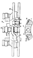
- Figure 1 est une coupe axiale du frein selon l'invention.
- Figure 2 est une demi-vue selon la flèche II de la figure 1, le voile de roue étant supposé enlevé.
- Figure 3 est une demi-vue selon la flèche III de la figure 1.
- Figure 4 est une vue selon la flèche IV de la figure 1, avec arraché et coupe partielle.
- Figure 5 est une vue d'un cavalier seul, parallèlement à la flèche V.
- Figure 1 is an axial section of the brake according to the invention.
- Figure 2 is a half-view along arrow II of Figure 1, the wheel disc being assumed removed.
- Figure 3 is a half-view along arrow III of Figure 1.
- Figure 4 is a view along arrow IV of Figure 1, with cutaway and partial section.
- Figure 5 is a view of a single rider, parallel to the arrow V.
Le dispositif décrit aux dessins est destiné à équiper une roue de véhicule. La pièce centrale du dispositif est un moyeu 1, de forme particulière, et qui a pour double fonction de relier la roue à son axe, et de porter les deux disques de frein.The device described in the drawings is intended to equip a vehicle wheel. The central part of the device is a hub 1, of particular shape, which has the dual function of connecting the wheel to its axis, and of carrying the two brake discs.
Le moyeu 1 comprend un plateau 2, de forme générale sensiblement circulaire, ayant en son milieu une partie plus épaisse 3, traversée par un trou 4 pourvu de cannelures 5, pour sa liaison avec l'arbre de roue 6, lequel est immobilisé par un écrou 7. Le plateau 2 porte, vers sa périphérie, trois prolongements 8 qui font saillie à la fois radialement et axialement. Les prolongements 8 sont en forme de fourche s'étendant dans un plan axial, c'est-à-dire que les extrémités de ces fourches se trouvent de part et d'autre du plan du plateau 2.The hub 1 comprises a
Les dessins montrent des prolongements fourchus 8 d'une seule pièce avec le plateau 2.The drawings show forked extensions 8 in one piece with the
Il est cependant possible de prévoir qu'une dent de la fourche, ou les deux, est une pièce distincte, maintenue par vissage par exemple sur le reste du moyeu. Cette solution, un peu plus compliquée, a l'avantage de faciliter de façon appréciable le montage, notamment la mise en place des colonettes décrites ci-après.It is however possible to provide that a tooth of the fork, or both, is a separate part, held by screwing, for example on the rest of the hub. This solution, a little more complicated, has the advantage of appreciably facilitating the assembly, in particular the installation of the small columns described below.
La face externe du plateau 2, c'est-à-dire celle qui est tournée vers l'extérieur du véhicule, à gauche sur la figure 1, porte le disque de freinage fixe 10 grâce à des vis 11 situées sensiblement dans le plan radial de symétrie des prolongements fourchus 8. La roue 12 est fixée sur le même plateau 2 par l'intermédiaire de vis de fixation 13, qui traversent le disque 10, et sont situées à égale distance de deux vis 11. Les vis de fixation 13, de diamètre nettement plus important que celui des vis 11 servent également à transmettre une grande partie des efforts de freinage directement du disque 10 à la roue 12. Les extrémités des prolongements fourchus 8 sont traversées par des alésages 14, dont l'axe commun est parallèle à l'axe de la roue, et dans lesquels sont montés des paliers 15.The external face of the
Des pièces cylindriques 16, ou "colonnettes", sont montées de façon à pouvoir coulisser dans les paliers 15. La longueur totale d'une colonnette est un peu supérieure à la distance entre les zones médianes des paliers 15. Un cavalier 17 est monté dans la partie centrale de la colonnette 16, sans déplacement axial possible par rapport à celle-ci, car il est immobilisé entre un épaulement 19 de la colonnette, et un jonc d'arrêt 20 maintenu dans une gorge 21 de la même colonnette. Les dimensions extérieures du cavalier 17 sont telles qu'il peut se déplacer entre les deux dents de la pièce fourchue 8, en entraînant la colonnette 16. Des obturateurs vissés 22 sont prévus aux deux extrémités de l'alésage interne 14. Un perçage 23 traverse axialement la colonnette 16. On conçoit que, si le volume intérieur des alésages 14 laissé libre par la colonnette 16 est rempli de graisse, celle-ci passera d'un côté à l'autre de la colonnette par ce passage lorsque celle-ci se déplace axialement dans un sens ou dans l'autre.
Pour compléter la protection des paliers 15 et des surfaces correspondantes de la colonnette, des manchettes souples 24 prenant appui dans une gorge 25 de la colonnette et sur le bord correspondant de la partie fourchue 8, empêchent toute agression par les agents atmosphériques extérieurs.To complete the protection of the
La forme du cavalier 17 est mieux visible aux figures 4 et 5. Il s'agit d'une pièce ayant une forme générale en V, dans un plan circonférentiel, avec une partie centrale traversée par un alésage 30, par lequel l'étrier est monté sur la colonnette 16, et deux ailes 31, pourvues de trous de fixation 32 par lesquels il est monté sur le disque mobile 33 par l'intermédiaire de vis 34, qui se vissent dans une partie épaissie 35 du disque 33.The shape of the
La figure 5 montre par ailleurs que, en vue axiale, le cavalier 17 a la forme d'un arc de cercle concentrique au moyeu 1.FIG. 5 also shows that, in axial view, the
Comme le montrent les figures 1 et 4, le disque fixe 10 a, en coupe axiale, une forme incurvée, telle que le plan de sa partie active, en haut sur la figure 1, est voisin du plan médian du plateau 2 du moyeu. Le cavalier 17 se trouve, lui aussi, à peu près dans le plan médian du moyeu 2. Pour loger ces différentes pièces, le disque fixe 10 comporte une fenêtre 40, de dimension suffisante pour laisser le passage non seulement à l'étrier 17, mais encore à l'extrémité de la partie fourchue 8 de façon à permettre le montage de ce disque fixe. On notera que la roue 12 porte, quant à elle, une fenêtre 41, plus petite que la fenêtre 40, et qui permet le passage de la partie fourchue 8. Le disque mobile 33, de son côté, présente des échancrures 42 pour le passage de l'extrémité interne de la pièce fourchue 8. Les trous de fixation 43 des vis 34 se trouvent, de part et d'autre, de l'échancrure 42. Ces dispositions de structure permettent, d'une part, d'écarter les disques de frein de la roue elle-même, et d'autre part de donner aux colonnettes 16 une longueur suffisante pour un bon coulissement.As shown in Figures 1 and 4, the fixed disc 10 has, in axial section, a curved shape, such that the plane of its active part, above in Figure 1, is close to the median plane of the
On a représenté en tirets les trois garnitures de freinage 50, 51, 52 et l'étrier 53 qui les porte (figure 1).There are shown in dashed lines the three
Claims (5)
Applications Claiming Priority (2)
| Application Number | Priority Date | Filing Date | Title |
|---|---|---|---|
| FR8805653A FR2630795B1 (en) | 1988-04-28 | 1988-04-28 | MULTIPLE DISC BRAKE |
| FR8805653 | 1988-04-28 |
Publications (2)
| Publication Number | Publication Date |
|---|---|
| EP0340058A1 EP0340058A1 (en) | 1989-11-02 |
| EP0340058B1 true EP0340058B1 (en) | 1991-06-19 |
Family
ID=9365765
Family Applications (1)
| Application Number | Title | Priority Date | Filing Date |
|---|---|---|---|
| EP89400914A Expired - Lifetime EP0340058B1 (en) | 1988-04-28 | 1989-04-04 | Brake with multiple discs |
Country Status (5)
| Country | Link |
|---|---|
| US (1) | US4984661A (en) |
| EP (1) | EP0340058B1 (en) |
| JP (1) | JPH01316528A (en) |
| DE (1) | DE68900122D1 (en) |
| FR (1) | FR2630795B1 (en) |
Families Citing this family (3)
| Publication number | Priority date | Publication date | Assignee | Title |
|---|---|---|---|---|
| GB2340562A (en) * | 1998-08-15 | 2000-02-23 | T & N Technology Ltd | Disc brake |
| GB0009514D0 (en) * | 1999-05-19 | 2000-06-07 | Mannesmann Sachs Ag | Clutch disc arrangement for a multiple disc clutch |
| US6988598B2 (en) * | 2001-11-26 | 2006-01-24 | Mark Williams Enterprises, Inc. | Disc brake rotor mounting system |
Family Cites Families (8)
| Publication number | Priority date | Publication date | Assignee | Title |
|---|---|---|---|---|
| US1998613A (en) * | 1933-03-17 | 1935-04-23 | Ford Motor Co | Engine clutch |
| JPS5712135A (en) * | 1980-06-25 | 1982-01-22 | Nissin Kogyo Kk | Multiple-disk brake for vehicle |
| FR2548303B1 (en) * | 1983-06-30 | 1985-10-25 | Dba | IMPROVEMENTS TO MULTI-DISC BRAKES |
| FR2555686B1 (en) * | 1983-11-30 | 1989-03-31 | Dba | MULTI-DISC BRAKE, COMPRISING A FIRST DISC AND A SECOND SLIDING DISC PROVIDED WITH A GUIDANCE SYSTEM |
| FR2565309B2 (en) * | 1983-11-30 | 1986-09-19 | Dba | BRAKING SYSTEM COMPRISING AT LEAST ONE SLIDING BRAKE DISC |
| DE8422260U1 (en) * | 1984-07-26 | 1985-04-25 | Alfred Teves Gmbh, 6000 Frankfurt | Disc brake wrapped around the inside, in particular for motor vehicles |
| JPS61112833A (en) * | 1984-11-05 | 1986-05-30 | Nippon Air Brake Co Ltd | Disc brake |
| FR2606105B1 (en) * | 1986-10-29 | 1988-12-02 | Bendix France | MULTI-DISC BRAKE |
-
1988
- 1988-04-28 FR FR8805653A patent/FR2630795B1/en not_active Expired - Lifetime
-
1989
- 1989-04-04 DE DE8989400914T patent/DE68900122D1/en not_active Expired - Lifetime
- 1989-04-04 EP EP89400914A patent/EP0340058B1/en not_active Expired - Lifetime
- 1989-04-24 US US07/342,913 patent/US4984661A/en not_active Expired - Fee Related
- 1989-04-25 JP JP1103578A patent/JPH01316528A/en active Pending
Non-Patent Citations (1)
| Title |
|---|
| PATENT ABSTRACTS OF JAPAN vol. 6, no. 71 (M-126)(949), 6 mai 1982 * |
Also Published As
| Publication number | Publication date |
|---|---|
| US4984661A (en) | 1991-01-15 |
| EP0340058A1 (en) | 1989-11-02 |
| JPH01316528A (en) | 1989-12-21 |
| FR2630795A1 (en) | 1989-11-03 |
| FR2630795B1 (en) | 1990-07-13 |
| DE68900122D1 (en) | 1991-07-25 |
Similar Documents
| Publication | Publication Date | Title |
|---|---|---|
| EP0080950B1 (en) | Floating caliper disk brake | |
| EP2361830A1 (en) | Landing gear wheel assembly provided with a wheel rotation device | |
| CA2816159C (en) | Aircraft wheel brake | |
| FR2893303A1 (en) | CYCLE PEDAL | |
| FR2537506A1 (en) | ARRANGEMENT FOR MOUNTING, ON A SUSPENSION, A ROTATING SHAFT OF A WHEEL OF A VEHICLE | |
| EP0722542B1 (en) | Disk brake with sliding caliper and stud for such disk brake | |
| EP0340058B1 (en) | Brake with multiple discs | |
| FR2855099A1 (en) | Lightweight hub for bicycle or similar vehicle has the hub supported on a lightweight tube with end fittings to secure the bearings and to connect to the forks | |
| WO2007036633A1 (en) | Safety module for transmission and corresponding assembly | |
| FR2491398A1 (en) | CASTER FOR HAND-HELD TRANSPORT TROLLEY | |
| EP0966620B1 (en) | Hybrid multiple disc brake | |
| EP1153768A1 (en) | Wheel mounting system on bridge or axle for motor vehicles | |
| EP1437521A1 (en) | Device for fixing a disc brake caliper on a stub axle, in particular for a motor vehicle | |
| FR2653075A1 (en) | IMPROVEMENTS IN TRANSMISSIONS OF VEHICLES EQUIPPED WITH ELECTRIC RETARDERS. | |
| FR2597798A1 (en) | DEVICE FOR COUPLING IN ROTATION OF A WHEEL HUB | |
| EP0789443B1 (en) | Vehicle transmission equipped with an electric retarder | |
| FR3039458A1 (en) | HUB FOR CYCLE WHEEL | |
| FR2560329A1 (en) | Torsion damper device especially for motor vehicle clutch friction disc | |
| EP2873610B1 (en) | Aircraft wheel equipped with a chain drive ring | |
| FR3005028A1 (en) | REMOVABLE WHEEL AXLE FOR VEHICLE TRAIN | |
| EP0789444B1 (en) | Vehicle transmission equipped with an electric retarder | |
| FR2744856A1 (en) | VEHICLE TRANSMISSION EQUIPPED WITH AN ELECTRIC RETARDER | |
| FR2631091A1 (en) | Torsion damper device with elastic circles, particularly for a motor vehicle | |
| FR2771149A1 (en) | Vehicle disc brake column with floating stirrup | |
| FR2751709A1 (en) | Roller bearing unit with conical rollers for circular shaft for machine tools |
Legal Events
| Date | Code | Title | Description |
|---|---|---|---|
| PUAI | Public reference made under article 153(3) epc to a published international application that has entered the european phase |
Free format text: ORIGINAL CODE: 0009012 |
|
| AK | Designated contracting states |
Kind code of ref document: A1 Designated state(s): DE FR GB IT |
|
| 17P | Request for examination filed |
Effective date: 19890926 |
|
| RAP1 | Party data changed (applicant data changed or rights of an application transferred) |
Owner name: BENDIX EUROPE SERVICES TECHNIQUES S.A. |
|
| 17Q | First examination report despatched |
Effective date: 19901126 |
|
| GRAA | (expected) grant |
Free format text: ORIGINAL CODE: 0009210 |
|
| AK | Designated contracting states |
Kind code of ref document: B1 Designated state(s): DE FR GB IT |
|
| REF | Corresponds to: |
Ref document number: 68900122 Country of ref document: DE Date of ref document: 19910725 |
|
| ITF | It: translation for a ep patent filed |
Owner name: STUDIO TORTA SOCIETA' SEMPLICE |
|
| GBT | Gb: translation of ep patent filed (gb section 77(6)(a)/1977) | ||
| PLBE | No opposition filed within time limit |
Free format text: ORIGINAL CODE: 0009261 |
|
| STAA | Information on the status of an ep patent application or granted ep patent |
Free format text: STATUS: NO OPPOSITION FILED WITHIN TIME LIMIT |
|
| 26N | No opposition filed | ||
| PGFP | Annual fee paid to national office [announced via postgrant information from national office to epo] |
Ref country code: GB Payment date: 19960326 Year of fee payment: 8 |
|
| PGFP | Annual fee paid to national office [announced via postgrant information from national office to epo] |
Ref country code: DE Payment date: 19960418 Year of fee payment: 8 |
|
| PGFP | Annual fee paid to national office [announced via postgrant information from national office to epo] |
Ref country code: FR Payment date: 19960423 Year of fee payment: 8 |
|
| PG25 | Lapsed in a contracting state [announced via postgrant information from national office to epo] |
Ref country code: GB Effective date: 19970404 |
|
| GBPC | Gb: european patent ceased through non-payment of renewal fee |
Effective date: 19970404 |
|
| PG25 | Lapsed in a contracting state [announced via postgrant information from national office to epo] |
Ref country code: FR Free format text: LAPSE BECAUSE OF NON-PAYMENT OF DUE FEES Effective date: 19971231 |
|
| PG25 | Lapsed in a contracting state [announced via postgrant information from national office to epo] |
Ref country code: DE Free format text: LAPSE BECAUSE OF NON-PAYMENT OF DUE FEES Effective date: 19980101 |
|
| REG | Reference to a national code |
Ref country code: FR Ref legal event code: ST |
|
| PG25 | Lapsed in a contracting state [announced via postgrant information from national office to epo] |
Ref country code: IT Free format text: LAPSE BECAUSE OF NON-PAYMENT OF DUE FEES;WARNING: LAPSES OF ITALIAN PATENTS WITH EFFECTIVE DATE BEFORE 2007 MAY HAVE OCCURRED AT ANY TIME BEFORE 2007. THE CORRECT EFFECTIVE DATE MAY BE DIFFERENT FROM THE ONE RECORDED. Effective date: 20050404 |