EP0340050A1 - Verfahren und Vorrichtung zum Transport von Feststoffen durch Aufschlämmen und Pumpen - Google Patents
Verfahren und Vorrichtung zum Transport von Feststoffen durch Aufschlämmen und Pumpen Download PDFInfo
- Publication number
- EP0340050A1 EP0340050A1 EP89400614A EP89400614A EP0340050A1 EP 0340050 A1 EP0340050 A1 EP 0340050A1 EP 89400614 A EP89400614 A EP 89400614A EP 89400614 A EP89400614 A EP 89400614A EP 0340050 A1 EP0340050 A1 EP 0340050A1
- Authority
- EP
- European Patent Office
- Prior art keywords
- pumping
- cuttings
- installation
- processing
- spreading
- Prior art date
- Legal status (The legal status is an assumption and is not a legal conclusion. Google has not performed a legal analysis and makes no representation as to the accuracy of the status listed.)
- Withdrawn
Links
- 238000009434 installation Methods 0.000 title claims abstract description 84
- 238000005086 pumping Methods 0.000 title claims abstract description 82
- 239000011343 solid material Substances 0.000 title claims abstract description 36
- 238000000034 method Methods 0.000 title claims abstract description 22
- 239000002002 slurry Substances 0.000 title abstract 3
- XLYOFNOQVPJJNP-UHFFFAOYSA-N water Substances O XLYOFNOQVPJJNP-UHFFFAOYSA-N 0.000 claims abstract description 58
- 238000005520 cutting process Methods 0.000 claims description 104
- 230000007480 spreading Effects 0.000 claims description 39
- 238000003892 spreading Methods 0.000 claims description 39
- 238000003860 storage Methods 0.000 claims description 30
- 238000010790 dilution Methods 0.000 claims description 28
- 239000012895 dilution Substances 0.000 claims description 28
- 239000007787 solid Substances 0.000 claims description 16
- 239000000463 material Substances 0.000 claims description 12
- 230000000916 dilatatory effect Effects 0.000 claims description 11
- 238000007865 diluting Methods 0.000 claims description 9
- 238000009412 basement excavation Methods 0.000 claims description 6
- 230000001131 transforming effect Effects 0.000 claims description 6
- 238000010276 construction Methods 0.000 claims description 5
- 230000008569 process Effects 0.000 claims description 5
- 238000007599 discharging Methods 0.000 claims description 2
- 238000010079 rubber tapping Methods 0.000 claims 1
- 230000009466 transformation Effects 0.000 description 11
- 239000002245 particle Substances 0.000 description 6
- 239000004927 clay Substances 0.000 description 4
- 239000000203 mixture Substances 0.000 description 4
- 239000013535 sea water Substances 0.000 description 3
- 239000013505 freshwater Substances 0.000 description 2
- 239000008241 heterogeneous mixture Substances 0.000 description 2
- 238000005554 pickling Methods 0.000 description 2
- 230000009467 reduction Effects 0.000 description 2
- 230000001105 regulatory effect Effects 0.000 description 2
- 239000000523 sample Substances 0.000 description 2
- 238000010008 shearing Methods 0.000 description 2
- 235000020354 squash Nutrition 0.000 description 2
- 238000000844 transformation Methods 0.000 description 2
- 230000005641 tunneling Effects 0.000 description 2
- 229910000831 Steel Inorganic materials 0.000 description 1
- 230000009471 action Effects 0.000 description 1
- 230000006978 adaptation Effects 0.000 description 1
- 239000004568 cement Substances 0.000 description 1
- 238000004140 cleaning Methods 0.000 description 1
- 238000004891 communication Methods 0.000 description 1
- 238000007796 conventional method Methods 0.000 description 1
- 230000008878 coupling Effects 0.000 description 1
- 238000010168 coupling process Methods 0.000 description 1
- 238000005859 coupling reaction Methods 0.000 description 1
- 230000010339 dilation Effects 0.000 description 1
- 238000009826 distribution Methods 0.000 description 1
- 238000005553 drilling Methods 0.000 description 1
- 230000000694 effects Effects 0.000 description 1
- 238000010616 electrical installation Methods 0.000 description 1
- 238000007710 freezing Methods 0.000 description 1
- 230000008014 freezing Effects 0.000 description 1
- 230000005484 gravity Effects 0.000 description 1
- 239000003673 groundwater Substances 0.000 description 1
- 239000008240 homogeneous mixture Substances 0.000 description 1
- 238000009413 insulation Methods 0.000 description 1
- 238000004898 kneading Methods 0.000 description 1
- 235000015090 marinades Nutrition 0.000 description 1
- 239000002184 metal Substances 0.000 description 1
- 238000005065 mining Methods 0.000 description 1
- 238000005192 partition Methods 0.000 description 1
- 238000005096 rolling process Methods 0.000 description 1
- 238000007789 sealing Methods 0.000 description 1
- 239000002893 slag Substances 0.000 description 1
- 239000000243 solution Substances 0.000 description 1
- 229910001220 stainless steel Inorganic materials 0.000 description 1
- 239000010935 stainless steel Substances 0.000 description 1
- 239000010959 steel Substances 0.000 description 1
- 239000008400 supply water Substances 0.000 description 1
- 239000000725 suspension Substances 0.000 description 1
- 238000011144 upstream manufacturing Methods 0.000 description 1
Images


Classifications
-
- E—FIXED CONSTRUCTIONS
- E21—EARTH OR ROCK DRILLING; MINING
- E21F—SAFETY DEVICES, TRANSPORT, FILLING-UP, RESCUE, VENTILATION, OR DRAINING IN OR OF MINES OR TUNNELS
- E21F13/00—Transport specially adapted to underground conditions
- E21F13/04—Transport of mined material in gravity inclines; in staple or inclined shafts
- E21F13/042—Vertical hydraulic conveying of coal
Definitions
- the invention relates to the transport and evacuation of solid materials capable of forming by water dilution a pumpable paste, in particular by piston pumps, between at least one site - in particular tunneling - and at least one area away from (or) site (s).
- the invention therefore aims to remedy the drawbacks of the prior art and aims to provide a method and an installation for transporting solids of the dilutable type by pumping, over long distances and with little water.
- the object of the invention is to make it possible to transport solid materials - in particular to evacuate cuttings - by using a process allowing the addition of a low weight of water, in particular less than the weight of the extracted cuttings.
- the object of the invention is also to make it possible to remove a very large volume of solid matter, in particular greater than a million cubic meters, for example of the order of two million cubic meters, with a very high flow rate in place of solid materials, in particular greater than 500 m3 / h, for example of the order of 650 m3 / h, and of transporting these solid materials by continuous pumping at a very large distance, in particular greater than 1000 m, for example of the order of 1500 m for materials liable to be diluted, for example cuttings of the clay chalk type.
- the invention also and more particularly aims to solve the problem of transporting and removing cuttings during the digging of a tunnel possibly comprising several tubes and whose length is greater than 15 km, in particular of the order of 20 km for each digging site with a flow in place of extracted cuttings greater than 500 m3 / h, in particular of the order of 650 M3 / h, without exhausting or polluting the water table in the vicinity of the tunnel.
- the object of the invention is also to propose a method and installations making it possible to transport solid materials such as cuttings or slabs, from a site in a discontinuous manner, then to pump these cuttings continuously towards a storage area or remote use.
- the invention provides a method of processing and transporting solid materials capable of forming a homogeneous paste by dilution, characterized in that the solid materials are diluted in water by means of dilution of so as to obtain a homogeneous paste with a low water content directly pumpable by pumping means.
- the diluted solid materials are transported by pumping in homogeneous paste formed by dilution in pipes, using piston pumps. Before pumping, spread the homogeneous paste formed by thinning on a spreading sole forming buffer storage between the thinning and pumping. The solid materials are crushed in crushing means before diluting them.
- the solid materials are diluted so that the ratio of the weight of water to the weight of dry solid material in the paste obtained is less than 70%, in particular of the order of 60%.
- the invention also relates to an installation for the transformation and transport by pumping of solid materials capable of forming a homogeneous paste by dilution, for the implementation of the method according to the invention.
- a solid material processing and transport installation according to the invention is characterized in that it comprises means for supplying the installation with solid materials, means for dissolving solid materials which are also supplied with water and making it possible to produce a homogeneous paste which can be pumped and means for pumping the homogeneous paste thus formed in pipes.
- the pumping means consist of a plurality of piston pumps, each pump supplying a discharge line to a storage or use area for the paste.
- the installation according to the invention comprises means for spreading the homogeneous paste obtained at the outlet of the dilating means, these spreading means forming buffer storage between the dilating means and the pumping means, and these spreading means. continuously supplying the pumping means.
- This installation according to the invention is in the form of a well, and further comprises, between the supply means and the dilution means, means for crushing dry solid materials.
- the supply means consist of at least one hopper opening onto at least one conveyor belt, each conveyor belt supplying from above two crusher devices opening into the dilating means, the dough flowing out of these diluting means. on a single spreading floor comprising a plurality of withdrawal openings distributed over its surface to supply respectively a plurality of piston pumps.
- the spreading sole has an area of the order of 1000 m2 and comprises at least eight racking openings having a useful racking section of the order of 1 m2 each.
- the invention also provides an installation for transporting and removing cuttings between at least one digging site for at least one tunnel. and at least one cuttings storage area remote from the site, characterized in that it comprises a plant for processing and transporting the cuttings according to the invention, means for transporting the cuttings from each excavation site to said installation for transformation and transport of cuttings by pumping and delivery pipes for cuttings transformed in the transformation and transport installation according to the invention into homogeneous paste pumpable by piston pumping means, these pipes making it possible to transport this paste by pumping continuously to said storage area.
- the installation for processing and transporting cuttings by pumping according to the invention is arranged between the two ends of at least one tunnel, so that it can be supplied with cuttings coming from two digging sites advancing in opposite directions.
- the invention thus makes it possible to evacuate the cuttings coming from each direction from two useful tunnels and from a adjoining service tunnel, and provides for this purpose five feed hoppers supplying respectively five dissolvers: one feed hopper for each useful tunnel direction and a feed hopper for the two service tunnel directions.
- the storage or use area of the paste obtained is located at a distance greater than 1000 m from the processing and transport installation according to the invention, in particular of the order of 1500 m, the pumping height between the pumping means and the storage or use area is greater than 100 m, in particular of the order of 150 m, and the discharge pipes have an internal diameter between 200 and 300 mm for a weight ratio d water on the weight of dry cuttings in the pumped pulp less than 70%, in particular of the order of 60%.
- the invention is advantageously applicable for transforming and pumping earthy cuttings, in particular clayey, coming from a digging site, in particular when these cuttings are of the clay chalk type. Nevertheless, the invention is applicable in any type of industry to transform and pump all kinds of solid materials, since these materials are capable of being diluted in water and of forming, during this dilution, a homogeneous paste with low water content. In particular, the invention is also applicable in the field of mining for transporting schlamms. The invention therefore consists in using the dilutable nature of these solid materials to transport them economically and advantageously, while these solid materials in the raw state cannot be pumped.
- the preferred embodiment shown of the invention relates to an installation and a method for transforming and pumping earthy cuttings - in particular clayey - coming from at least one site 1 for digging at least one tunnel 2, and for transporting these cuttings to at least one storage or use area 3 of the cuttings distant from said site 1.
- the preferred embodiment shown of the invention corresponds to an installation for transporting and removing cuttings used for the digging of a triple underwater tunnel with two rail tracks or road. It is however understood that the invention is applicable to any other site or industry in which the same technical problems would arise.
- the invention is advantageously applicable to tunneling sites, for example under water bodies, such as underwater tunnels or others.
- the invention is also applicable for other solid materials than earthy or clayey cuttings, since these materials are likely to form fines by a mechanical action of dilution with water to form a homogeneous paste with fine content allowing pumping this paste, in particular by piston pumps. For example, this is the case for all earthy materials (clay, chalk, shale, or other earth ...) but also schlamms or all other industrial products of equivalent nature.
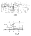
- the installation for transporting and removing cuttings according to the invention is schematically represented in vertical section in FIG. 1. It comprises: an installation 4 according to the invention for processing and transporting the cuttings by pumping which come from said sites, means 5 for transporting the cuttings from each excavation site 1 to said processing and transport facility 4 for the cuttings by pumping, - pipes 6 for discharging cuttings transformed in the processing and transport installation 4, into homogeneous paste pumpable by piston pumps, these pipes making it possible to transport this paste by continuous pumping to the storage area or of use 3.
- the installation for transforming and transporting cuttings 4 by pumping according to the invention is for example in the form of a vertical well, and two tunnels 2, 2 ′ extending in directions have been shown by way of example opposite on each side of this well-shaped installation 4.
- Two tunne liers 7, 7 ′ make it possible to dig tunnels with full sections.
- the cuttings created at the exit from the tunnel boring machines are dumped directly, possibly after mixing and little addition of water in the tunnel bikes exit train, in vans 5 rolling on rails which lead directly through the already dug tunnel to the processing and pumping installation 4 of the cuttings.
- the wagons 5 can be self-propelled, or driven by towing cables or by other equivalent systems.
- the two sites 1, 1 ′ of tunnels shown make it possible to dig on the one hand a main tunnel 2 extending under the water table 9, and on the other hand a secondary tunnel 2 ′ which constitutes the access ramp to the main tunnel 2.
- the storage or use area 3 may consist of a depression in the ground, or an excavation made in the ground, and is located at a distance of between 1000 and 2000 meters, in particular of the order of 1500 meters from the excavation processing and pumping facility 4.
- each tunnel 2, 2 ′ consists of three galleries 2a, 2b, 2c, 2′a, 2′b, 2′c: two useful galleries 2a, 2b, 2 ′ A, 2′b, and a central service gallery 2c, 2′c.
- the main galleries 2a, 2b, 2c are respectively opposite and correspond to the secondary galleries 2′a, 2′b, 2′c.
- the tunnels 2, 2 ′ extend at the level of the processing and transport installation 4 according to the invention, substantially in the same direction in opposite directions. This common direction is called longitudinal direction.
- the horizontal direction perpendicular to the longitudinal direction will be called the lateral direction.
- the expression “cuttings extracted in place” designates the cuttings actually extracted during digging at the level of the tunnel boring machine, that is to say also the flow rate of dry solids transported. The flow in place of excavated cuttings is therefore the flow of cuttings formed on the digging section by the tunnel boring machine.
- the term "dilution" and the terms which relate to it refer to the operation consisting in producing an intimate homogeneous mixture from the cuttings by little addition of water, as opposed to simple mixing or kneading which does not make it possible to carry out than heterogeneous mixtures.
- the dilution is conventionally characterized by a particle size of the particles in the mixture which varies between 0 and about 60 mm, and by a content of fines (that is to say in particles whose size is less than about 80 micrometers) greater than 20%, in particular of the order of 35% by weight.
- the paste thus obtained therefore has a creamy appearance, and is pumpable despite a low water content.
- a cuttings processing and pumping installation 4 is characterized in that it is notably comprises successively from top to bottom: - Means 10, 11 for supplying extracted cuttings, in particular consisting of at least one feed hopper 10 collecting the cuttings spilled from the wagons 5, feeding at least one conveyor belt 11 which discharges these cuttings in the longitudinal direction towards a longitudinal end 12 of this strip 11, end 12 situated beyond the longitudinal end 13 of said hopper 10, means 14 for dissolving the cuttings, which are also supplied with water and making it possible to produce a homogeneous paste which can be pumped by piston pumping means, means 15 for spreading the dough obtained at the outlet from the means 14 for dilating, - Means 16 for pumping the dough recovered at the outlet and under said means 15 for spreading.
- These pumping means 16 are of the piston type and comprise at least one and generally a plurality of piston pumps.
- means 17 for crushing the cuttings extracted before shearing there are provided means 17 for crushing the cuttings extracted before shearing.
- the cuttings processing and pumping installation 4 is in the form of a vertical well, and the cuttings pass successively from top to bottom, under the effect of their own weight, in the following devices: feed 10, conveyor belt 11, crushing means 17 which reduce them to a particle size capable of being diluted, dilating means 14 which transform them into a homogeneous paste pumpable by piston pumping means, spreading means 15 which supply the means 16 continuous piston pumping.
- the supply means 10, 11 therefore consist of at least one hopper 10 leading to at least one conveyor belt 11, each conveyor belt 11 supplying from above two crusher devices 17, the lower outlet 18 of which opens into dilating means 14, the dough flowing through gravitation at the outlet of these dilating means 14 on a single spreading sole 15 comprising a plurality of withdrawal openings 19 distributed over its surface to supply a plurality of pumps 16 located under the sole 15.
- These pumping means 16 are constituted piston pumps 16, each pump 16 supplying a discharge line 6 to a storage area 3 for the paste, and receiving the paste coming from an opening 19 in the spreading sole 15.
- Each opening 19 in the sole spreader 15 is fitted with a valve 20, for example a slide valve, allowing this opening 19 to be closed and opened at will.
- the supply means 10, 11 are better represented in detail in FIG. 5. They are composed, for each crushing and dilution circuit, of a metal hopper hopper 10 with vertical longitudinal walls 21.
- the length of each hopper 10 is adapted to correspond to that of a conveyor belt 11 located immediately under and facing the hopper 10 and to that of a group of wagons.
- Each hopper 10 is supplied with cuttings from the wagons 5 by means of rocking devices 22 of these wagons 5 visible in FIG. 3.
- rocking devices are known in themselves and for example consist of a cylinder mounted on bearings 23 and comprising rails 24 for supporting and holding the wagons 5 during tilting. During the tilting of the wagons 5, these discharge into a deflector which is connected to the discharge wall 21 of a hopper 10.
- each hopper 10 has a length sufficient to be fed simultaneously by three wagons 5 arranged one after the other in the longitudinal direction. This of course allows considerably increase the throughput of extracted cuttings which will be treated later. However, this also requires the use of a conveyor belt 11 under each hopper 10 to collect the cuttings extracted for processing in the crushing devices 17 and dissolvers 14 and to regulate the flow of cuttings discharged into the crushers 17 and the shredders 14.
- the length of the upper opening of each hopper 10 is of the order of 21 m
- the length of the lower opening is of the order of 17m
- the width is of the around 2m
- the height is around 3.60m (for a height of excavated material dumped at each tilting around 1m.
- the conveyor belt 11 is mounted on rollers 25. It is driven by drums 26, 27 one of which 27 is motorized and connected to a motor 29 which is preferably an asynchronous electric motor rotating at 1450 rpm connected to the drum 27 thanks to a hydraulic coupler, a mechanical variator, a torque limiter, a gear coupling, a reduction gear with perpendicular shafts.
- the conveyor belt 11 opens into a connecting chute 28 supplying the crusher device 17 in the lower part.
- the side walls of this chute 28 are undercut, and the wall opposite to the conveyor belt 11 has a positive skin but limited for example to 22 ° and permanently watered to avoid clogging.
- These chutes 28 are preferably made of stainless steel to promote the sliding of the material.
- a central partition is provided which divides the material stream longitudinally in each trough 28 to ensure a good distribution of the supply of the two crushers 17 .
- the lateral seal between the hopper 10 and the corresponding conveyor belt 11 is reinforced, in particular by the use of a flat sliding surface in place of the conventionally provided upper side rollers.
- the lateral sealing can also be improved by the use of lateral flaps.
- Each of these crushers 17 is for example made up of two toothed cylinders 30, 31 driven in rotation at two different speeds, and whose spacing one with respect to the other is adjustable as desired according to the desired particle size and to compensate for the wear of the teeth of the cylinders 30, 31.
- a first cylinder 30 is mounted movable relative to the chassis 32 of the crusher 17, while the another cylinder 31 is mounted on bearings 33 fixed to the chassis 32.
- the bearings 34 of the movable cylinder 30 are arranged so that they can slide in guide grooves of the chassis 32 in the direction of the spacing of the fixed cylinder 31.
- Each movable bearing 34 is held in position relative to the chassis 32 by means of two return devices 35 each consisting of a stop 36 cooperating with the bearing 34 and with a spring 37 whose calibration can be adjusted.
- Each stop 36 is mounted at the end of a sliding rod in an axis 38 integral with a plate 39 which can slide relative to the chassis 32 but whose movements opposite the fixed cylinder 31 are limited by a screw stop 40.
- the stop screw 40 makes it possible to give a predetermined position to each bearing 34 via the return devices 35.
- the movable cylinder 30 can deviate against the springs 37 to allow this body to pass, and automatically return to its initial predetermined position by the position of the stop screws 40.
- Each cylinder 30, 31 is rotated by a pulley 41, 42 cooperating moreover with motorization devices via belts.
- the cuttings crushed in the crusher devices 17 fall directly into a dissolving device 14.
- advantageously two crusher devices 17 are provided per dissolving device 14, and this because of the high throughput, but also for safety purposes.
- these crusher devices 17 can become blocked and thus put the whole of the corresponding circuit for processing the cuttings off. It is therefore desirable to be able to have at least one emergency crusher 17 which avoids the interruption of the entire circuit.
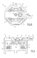
- a dissolving device 14 of the cement dissolving type is shown in FIGS. 8 and 9. It consists of an octagonal shaped tank 43 constructed of concrete, and comprising a central support 44 which extends vertically upwards from the bottom of the tank 43. On this central support 44 is associated in rotation a mechanically welded cross 45 in profiled bars which, by a chain suspension 46, carries harrows 47.
- the mechanically welded cross 45 forms four branches supporting respectively four harrows 47 which move in the circular corridor of the tank 43 defined by the external walls 48 of this tank and the central support 44.
- the mechanically welded cross 45 extends horizontally and is associated with the support 44 in rotation around a fixed vertical shaft 49.
- This cross 45 is fixed by bolting to the underside of another cross 50 which carries a toothed crown 51.
- the assembly 45, 50, 51 is integral in rotation with the vertical shaft 49 which is guided at its upper part ieure 52 by a head 53 forming a bearing and cooperating with an upper cross member 54 of the tank 43.
- This cross member 54 also supports a motor 55 connected by a reduction gear 56, a torsion shaft 57, a conical bevel gear 58 and a pinion straight 59 to the toothed crown 51 to drive the cross 45 in rotation, for example in the direction of the arrow F in FIG. 8.
- Each of the harrows 47 comprises for example three rows of steel teeth whose positioning is such that it allows easy replacement of these teeth.
- Each harrow 47 is also suspended by chains 46 which include in particular four carrying chains connected to the branch of the cross 45 situated above said harrow 47, two guide chains connected to an upstream branch of the mechanically welded cross 45, and two traction chains connected to the cross 50 supporting the drive crown 51.
- the cuttings at the outlet of the crushers 17 are poured directly as they are produced into the tank 43.
- This tank 43 has grids 60 for dumping over a certain portion of its periphery, through which the diluted mixture is poured by overflowing outlet of the shredder.
- the outgoing flow of the diluted paste corresponds to the flow of cuttings poured into the dissolver 14.
- the number and positioning of these grids 60 is adapted as a function of the position and the flow of the dissolver 14 relative to the spreading floor 15.
- Each grid 60 preferably consists of a coarse grid located towards the inside of the tank 43 and rigidly associated with the wall 48 of this tank 43, and a fine grid liftable thanks to a winch device.
- the fine grid is turned towards the outside of the dissolver 14. This fine grid can be used to produce in the dissolvers 14 a fine mixture used to lubricate the delivery pipes 6 before pumping the dough produced from the cuttings.
- Each spreader 14 preferably comprises three sets 60 of discharge grids disposed respectively on three successive contiguous sides of the octagon constituting the outer walls 48 of the tank 43 ( Figure 8).
- the paste obtained after the dilation at the outlet of the grids 60 of each of the dilutants 14 is directly poured onto the spreading sole 15.
- the positioning of the grids 60 relative to the openings 19 of the spreading sole is shown by the arrows 61 shown in figure 2.
- the installation for transporting and removing cuttings according to the invention shown in the figures makes it possible to remove cuttings from each direction from two useful tunnels 2a, 2b, 2′a, 2′b and a service tunnel 2c, 2′c adjoining.
- the installation for processing and transporting the cuttings 4 by pumping comprises five feed hoppers 10 supplying respectively via five conveyor belts 11 ten crushers 17 (two per conveyor belt 11) which feed in pairs five dissolvers 14 respectively.
- a feed hopper 10 is provided respectively for each direction of useful tunnels 2a, 2′a, 2b, 2′b and a feed hopper 10 is provided for the two directions of the service tunnel 2c, 2′c.
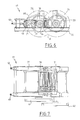
- the three wagons 5 on the left in FIG. 4 come from the main useful tunnel 2 and discharge simultaneously into the left hopper 10.
- the three wagons 5 on the right in FIG. 4 come from the secondary useful tunnel 2 ′ and discharge into the right hopper 10.
- the hopper 10 supplied with cuttings coming from the tunnel service 2c or 2′c is preferably located in the central part of the installation 4.
- the two main portions 2c and secondary 2′c of the service tunnel are dug simultaneously but at a lower flow rate and alternately supply the same central hopper 10 .
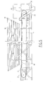
- the arrangement of the five feed hoppers 10 and the five corresponding shredders 14 is illustrated in FIG. 2 with respect to the openings 19 of the spreading hearth 15.
- the feed hoppers 10 being generally symmetrically and regularly distributed in the processing and pumping installation 4, the crushers 17, the shredders 14, the spreading hearth 15, the pumps 16, and their associated devices, are generally offset on one side of the installation 4, in particular on the side of the water table 9, that is to say on the side of the main tunnels 2a, 2b, 2c as shown in FIG. 2.
- the portion 62 of the section of the processing and transport installation 4 according to the invention which is oriented towards the ground preferably receives the electrical installations and the access routes 63 at the different levels of the processing and transport 4 according to the invention.
- the top of the figure is oriented towards the water table 9, while the bottom of the figure is oriented towards the earth.
- the processing and transport installation 4 of the cuttings by pumping has a circular horizontal cross section.
- the spreading hearth 15 has at least nine draw-off openings 19 which directly feed the piston pumps 16 via slide valves 20. These draw-off openings 19 are also arranged in a non-symmetrical manner with respect to the central axis of the 'processing and pumping installation 4 of the cuttings according to the invention, and are arranged, for the major part of them, in the section portion oriented towards the water table 9.
- the spreading sole 15 comprises forms of suitable slopes on its upper surface to guide the dough discharged at the outlet of the shredders 14 towards the various withdrawal openings 19 automatically by gravitation.
- slopes can be studied and produced in an obvious manner by a person skilled in the art depending on the respective positions of the different dissolvers 14, of their outlet grids 60, and of the withdrawal openings 19 distributed over the surface of the spreading hearth 15 for a regular supply of the pumps 16. Filter grids can also be provided in the openings 19 to prevent particles of too large a size possibly still suspended in the paste from reaching the piston pumps.
- Each withdrawal opening 19 is connected directly to the suction of a piston pump 16 as shown in FIG. 10.
- this connection 64 is flexible and includes a pressure relief safety valve.
- the spreading floor 15 advantageously comprises an access slope 65 for a self-propelled cleaning machine such as a bulldozer 66.
- the piston pumps 16 are fixed to the lower floor 67 of the processing and transport installation 4 according to the invention, which forms the bottom of the well. They are sized according to the flow of cuttings to be extracted and evacuated. Each piston pump 16 is driven by a hydraulic unit 68. The outlet of each of the pumps 16 is connected to a discharge line 6 via a shut-off valve 69. As many piston pumps 16 are preferably provided as there are openings 19 in the spreading floor 15. More specifically, it is necessary to provide as many pumps 16 as there are openings 19 simultaneously open when using the invention. One can foresee for example that only eight among the nine openings 19 of the spreading hearth 15 will be open simultaneously. Consequently, only eight pumps are provided which are disposed respectively under these eight openings, one of the pumps being transported when one of the openings 19 is closed to open another, as the work progresses.
- the eight discharge pipes 6 at the outlet of the pumps 16 are grouped together at 70 to exit towards the storage or use area 3.
- the cylindrical outer wall 8 of the well forming the processing and pumping installation 4 of the cuttings according to the invention makes it possible to delimit water tanks or albraques.
- a collector 75 connects the two albraques 71, 72, and allows a free communication of the water between them, so that the water contained in each albraque 71, 72 can be fresh, brackish or sea water.
- Pumps 73 are arranged at the bottom of the albraque 72 in fresh water on the land side. These pumps 73 supply water by a network of appropriate pipes to the different shredders 14. There are adjustable valves on these pipes, so that the flow of water supplied to the shredders 14 can be easily regulated.
- the invention provides a method of processing and transporting solid materials capable of forming a homogeneous paste by dilution, such as cuttings coming from at least one site 1, in particular at least one tunnel boring machine, with a view to pumping them via pipes 6 to at least one storage or use area 3 of the cuttings distant from said site 1, characterized in that the solid materials are diluted by means 14 of dilution so as to obtain a homogeneous paste directly pumpable by piston pumps 16, paste which is spread on a spreading floor 15 forming a buffer storage between the dilating means 14 and pumping means 16 comprising piston pumps, then the pumping means 16 are supplied with the paste at the outlet of the spreading floor 15 and this paste is pumped continuously to the storage or use area 3 by means of delivery pipes 6.
- the cuttings are crushed in means 17 of crushing before diluting them.
- the invention also relates to such a process for transforming and transporting solid materials between a mobile construction site 1 and an area 3 remote from said construction site 1, characterized in that the solid materials are transported between construction site 1 and the processing installation and transport 4 discontinuously, for example by means of wagons 5 the content of which is poured into feed hoppers 10, and the means 14 for diluting are fed, possibly via the means 17 for crushing when these are provided , by means of a conveyor belt 11 placed under each hopper 10, and the homogeneous paste obtained by dilution is pumped through pipes 6 leading to said area 3.
- the flow rate of cuttings discharged into the dilution means 14 is adjusted, possibly via the means 17 for crushing by adjusting the speed of advance of each conveyor belt 11.
- the wagons 5 are poured in groups, in particular in groups of three, into the same hopper 10, the solid materials are collected in crushing means 17, in particular by means of the conveyor belt 11, then these materials are crushed solid and diluted in the diluting means 14.
- solid means are successively supplied with the means 17 for crushing, 14 for diluting, 15 for spreading, 16 for pumping the transformation and pumping installation 4 according to the invention by gravitation, these different means 17 crushing, dilating, 15 spreading and 16 pumping being arranged one above the other or at least substantially one above the other under the feed hoppers 10 into which the solids are poured from the wagons 5 .
- the installation for transporting and removing the cuttings according to the invention is characterized in that the installation for transforming and transporting the cuttings 4 by pumping according to the invention is arranged between the two ends of at least one tunnel 2 , so that it can be supplied with cuttings from two sites 1, 1 ′ of digging advancing in opposite directions to produce this same tunnel.
- the tunnel 2 is then composed of a main part 2 and a secondary part 2 ′ separated by the processing and pumping installation 4 of the cuttings according to the invention.
- An installation for transporting and removing cuttings according to the invention for which the tunnel (s) is (are) intended to extend in one direction under a sheet of water 9 and to open out of the earth in the other direction, is characterized in that the processing and transport installation 4 of the cuttings by pumping is arranged at least in the vicinity of the bank of this sheet of water 9.
- the storage or use area 3 of the paste obtained can be located at a distance greater than 1000 meters from the processing and transport installation 4, in particular of the order of 1500 meters, the pumping height between the pumping means 16 and the storage or use area 3 may be greater than 100 meters, in particular of the order of 150 meters, and it is possible to use delivery pipes 6 with an internal diameter of the order of 255 mm.
- delivery pipes 6 For a flow in place of cuttings extracted from building sites 1, 1 ′ of the order of 650 m3 / h, eight delivery pipes 6 are used supplied respectively by an identical number of piston pumps 16.
- These piston pumps 16 are sized for that the pulp flow in each discharge line 6 is adapted to the flow in place of the excavated material desired, and in particular is of the order of 150 m3 / h of pulp.
- the extracted cuttings of the clay chalk type are diluted so that the ratio of the weight of water to the weight of dry cuttings in the pulp obtained for pumping is less than 70%, in particular of the order of 60%.
- the spreading sole 15 has an area on the order of 1000 m2 and comprises at least eight racking openings 19 having a useful racking section of the order of 1m2 each .
- the piston pumps are sized on a peak unit flow rate of 90 m3 / h of extracted cuttings.
- the delivery pipes 6 have an internal diameter between 200 mm and 300 mm, a thickness between 5 and 15 mm to provide a delivery at 1500 meters distance with an elevation of 150 meters at a flow rate of 150 m3 / h and a maximum operating pressure in each line 6 of 80 bars.
- Eight lines 6 are used from eight piston pumps 16 in service. Lines 6 and fittings are protected from freezing by appropriate insulation.
- the pumps 73 for supplying water to the dissolvers 14 consist, for example, of three pumps capable of an hourly flow rate of 720 m3 at a total head height of 25 meters.
- the water content of the materials which are poured into the wagons 5 is measured by size analysis, then the quantity of water is determined. add according to a known abacus. We then program the supply of dilution water. Start-up is then carried out by checking the arrangement of the grids 60 and the condition of the chains 46, then starting the shredders 14, starting the crushers 17, putting in running of the conveyor belts 11, choice, positioning and arming of the piston pumps 16, opening of the various appropriate valves. Before starting up the installation, the discharge pipes 6 must be lubricated. A very fine mixture can be used for this, such as fine chalk slip, the water content of which is approximately 80% produced by means of the fine grids of the dissolvers 14.
- the supply of dilution water begins in the dilutants 14 and is carried out until the programmed quantity has passed.
- the pouring of the ground product into the shredders 14 which can be regulated by the speed of advance of each conveyor belt 11, causes the shedding of the shredded product contained in the shredders 14 onto the spreading floor 15 by overflow.
- the rise in the level of diluted dough on the suction grid of the piston pump 16 in service causes this pump to start up and its speed to be adjusted, which is preferably controlled automatically by an ultrasonic probe.
Landscapes
- Engineering & Computer Science (AREA)
- Mining & Mineral Resources (AREA)
- Mechanical Engineering (AREA)
- Life Sciences & Earth Sciences (AREA)
- General Life Sciences & Earth Sciences (AREA)
- Geochemistry & Mineralogy (AREA)
- Geology (AREA)
- Excavating Of Shafts Or Tunnels (AREA)
- Crushing And Pulverization Processes (AREA)
Applications Claiming Priority (2)
| Application Number | Priority Date | Filing Date | Title |
|---|---|---|---|
| FR8802808 | 1988-03-04 | ||
| FR8802808A FR2628145A1 (fr) | 1988-03-04 | 1988-03-04 | Procede et installation de transformation et de pompage de deblais a sole d'epandage, et installation de transport de deblais avec une telle installation |
Publications (1)
| Publication Number | Publication Date |
|---|---|
| EP0340050A1 true EP0340050A1 (de) | 1989-11-02 |
Family
ID=9363934
Family Applications (1)
| Application Number | Title | Priority Date | Filing Date |
|---|---|---|---|
| EP89400614A Withdrawn EP0340050A1 (de) | 1988-03-04 | 1989-03-03 | Verfahren und Vorrichtung zum Transport von Feststoffen durch Aufschlämmen und Pumpen |
Country Status (3)
| Country | Link |
|---|---|
| EP (1) | EP0340050A1 (de) |
| FR (1) | FR2628145A1 (de) |
| PL (1) | PL278055A1 (de) |
Cited By (1)
| Publication number | Priority date | Publication date | Assignee | Title |
|---|---|---|---|---|
| CN112814596A (zh) * | 2019-10-31 | 2021-05-18 | 中国石油化工股份有限公司 | 一种取岩屑装置 |
Citations (7)
| Publication number | Priority date | Publication date | Assignee | Title |
|---|---|---|---|---|
| FR1567005A (de) * | 1966-03-28 | 1968-05-16 | ||
| US3982789A (en) * | 1974-07-16 | 1976-09-28 | Kamyr, Inc. | Process and apparatus for conveying large particle mined coal, oil shale, ore, etc. from underground mines or from strip mines via a pipeline |
| GB1475474A (en) * | 1975-10-09 | 1977-06-01 | Continental Oil Co | Method and apparatus for hydraulically transporting solids |
| FR2351282A1 (fr) * | 1976-05-15 | 1977-12-09 | Ackermann Robert | Dispositif de pompage |
| US4114854A (en) * | 1977-06-10 | 1978-09-19 | Pac-Craft Products, Inc. | Scissors lift work platform |
| DE3312360A1 (de) * | 1983-04-06 | 1984-10-11 | Hansjürgen Dr. 4630 Bochum Ullrich | Verfahren zur hydraulischen foerderung von feststoffen |
| EP0197402A2 (de) * | 1985-04-11 | 1986-10-15 | PREUSSAG Aktiengesellschaft Metall | Vorrichtung zur Förderung von Dickstoffsuspensionen und Verfahren zu ihrem Betrieb |
Family Cites Families (1)
| Publication number | Priority date | Publication date | Assignee | Title |
|---|---|---|---|---|
| US4114954A (en) * | 1977-05-23 | 1978-09-19 | Falconbridge Nickel Mines Limited' | Hydraulic hoisting |
-
1988
- 1988-03-04 FR FR8802808A patent/FR2628145A1/fr active Pending
-
1989
- 1989-03-03 PL PL27805589A patent/PL278055A1/xx unknown
- 1989-03-03 EP EP89400614A patent/EP0340050A1/de not_active Withdrawn
Patent Citations (7)
| Publication number | Priority date | Publication date | Assignee | Title |
|---|---|---|---|---|
| FR1567005A (de) * | 1966-03-28 | 1968-05-16 | ||
| US3982789A (en) * | 1974-07-16 | 1976-09-28 | Kamyr, Inc. | Process and apparatus for conveying large particle mined coal, oil shale, ore, etc. from underground mines or from strip mines via a pipeline |
| GB1475474A (en) * | 1975-10-09 | 1977-06-01 | Continental Oil Co | Method and apparatus for hydraulically transporting solids |
| FR2351282A1 (fr) * | 1976-05-15 | 1977-12-09 | Ackermann Robert | Dispositif de pompage |
| US4114854A (en) * | 1977-06-10 | 1978-09-19 | Pac-Craft Products, Inc. | Scissors lift work platform |
| DE3312360A1 (de) * | 1983-04-06 | 1984-10-11 | Hansjürgen Dr. 4630 Bochum Ullrich | Verfahren zur hydraulischen foerderung von feststoffen |
| EP0197402A2 (de) * | 1985-04-11 | 1986-10-15 | PREUSSAG Aktiengesellschaft Metall | Vorrichtung zur Förderung von Dickstoffsuspensionen und Verfahren zu ihrem Betrieb |
Cited By (2)
| Publication number | Priority date | Publication date | Assignee | Title |
|---|---|---|---|---|
| CN112814596A (zh) * | 2019-10-31 | 2021-05-18 | 中国石油化工股份有限公司 | 一种取岩屑装置 |
| CN112814596B (zh) * | 2019-10-31 | 2022-12-27 | 中国石油化工股份有限公司 | 一种取岩屑装置 |
Also Published As
| Publication number | Publication date |
|---|---|
| FR2628145A1 (fr) | 1989-09-08 |
| PL278055A1 (en) | 1989-10-16 |
Similar Documents
| Publication | Publication Date | Title |
|---|---|---|
| KR100403753B1 (ko) | 주행수단을 가지는 토양처리기 | |
| EP2746463A1 (de) | Vorrichtung, Baggervorrichtung und Verfahren zum Transport von aus einer Flüssigkeit aufgenommenem Material | |
| US2857691A (en) | Pipeline ditch filling and pipe padding machine | |
| WO2018049411A1 (en) | Systems and methods for processing earthen slurries | |
| CA1261888A (en) | Open-cut-mining milling unit | |
| CN111729933B (zh) | 一种土壤修复药剂混合设备及工艺 | |
| DE69501678T2 (de) | Schiff, Baggereinrichtung und deren Zusammenbau | |
| DE19715284A1 (de) | Unterwasser-Mineralgewinnungsgerät | |
| CN101864781B (zh) | 清淤采掘机 | |
| CN218347386U (zh) | 一种富水砂卵石地层泥水盾构环流系统 | |
| FR2628145A1 (fr) | Procede et installation de transformation et de pompage de deblais a sole d'epandage, et installation de transport de deblais avec une telle installation | |
| EP0317824B1 (de) | Maschine und Verfahren zum kontinuierlichen Lösen und Abfördern von Gestein | |
| JP2524835B2 (ja) | シ―ルド機械 | |
| US708395A (en) | Device for digging ditches. | |
| US3290804A (en) | Consolidating apparatus | |
| US2701653A (en) | Installation for the storage and distribution of molding earth, manures, and the like | |
| EP1053372B1 (de) | Maschine zum umsetzen von mieten | |
| CN210597200U (zh) | 一种流动化处理疏浚淤泥的装置 | |
| EP1072370B1 (de) | Verfahren und Vorrichtung zur Behandlung von Materialien hauptsächlich bestehend aus feuchtem Ton, insbesondere Bodenaushub | |
| CN217249554U (zh) | 工程施工用土方破碎装置 | |
| CN213728537U (zh) | 一种土壤修复药剂混合设备 | |
| FR2833194A1 (fr) | Dispositif et procede de traitement de materiaux mineraux tels que des terres ou des materiaux de recuperation | |
| CN108176521A (zh) | 淤泥脱水装置及具有淤泥脱水装置的清淤干泥船 | |
| JPH0374289B2 (de) | ||
| EP2530237B1 (de) | Station zur Aufbereitung von Schlämmen, die mit einem Tunnelbohrgerät mit unter Druck stehender Angriffsfläche verbunden ist, und Steuerungverfahren einer solchen Station |
Legal Events
| Date | Code | Title | Description |
|---|---|---|---|
| PUAI | Public reference made under article 153(3) epc to a published international application that has entered the european phase |
Free format text: ORIGINAL CODE: 0009012 |
|
| AK | Designated contracting states |
Kind code of ref document: A1 Designated state(s): AT BE CH DE ES FR GB GR IT LI LU NL SE |
|
| STAA | Information on the status of an ep patent application or granted ep patent |
Free format text: STATUS: THE APPLICATION IS DEEMED TO BE WITHDRAWN |
|
| 18D | Application deemed to be withdrawn |
Effective date: 19900503 |