EP0339898A2 - Wurfpfeilziel mit elektronischer Trefferanzeige - Google Patents
Wurfpfeilziel mit elektronischer Trefferanzeige Download PDFInfo
- Publication number
- EP0339898A2 EP0339898A2 EP89304039A EP89304039A EP0339898A2 EP 0339898 A2 EP0339898 A2 EP 0339898A2 EP 89304039 A EP89304039 A EP 89304039A EP 89304039 A EP89304039 A EP 89304039A EP 0339898 A2 EP0339898 A2 EP 0339898A2
- Authority
- EP
- European Patent Office
- Prior art keywords
- conductive
- target board
- conductive layer
- projectile
- layer
- Prior art date
- Legal status (The legal status is an assumption and is not a legal conclusion. Google has not performed a legal analysis and makes no representation as to the accuracy of the status listed.)
- Granted
Links
Images


Classifications
-
- F—MECHANICAL ENGINEERING; LIGHTING; HEATING; WEAPONS; BLASTING
- F41—WEAPONS
- F41J—TARGETS; TARGET RANGES; BULLET CATCHERS
- F41J5/00—Target indicating systems; Target-hit or score detecting systems
- F41J5/04—Electric hit-indicating systems; Detecting hits by actuation of electric contacts or switches
- F41J5/044—Targets having two or more electrically-conductive layers for short- circuiting by penetrating projectiles
Definitions
- This invention relates to a target board for electrically sensing the penetration of darts and similar missiles that do not penetrate entirely through the target. More specifically, the invention relates to the construction of a target board that is adapted to be a sensing device to trigger an electrical scoring device not of this invention wherein an electrical trigger circuit is closed upon the impact of a pointed missile partially penetrating the target board.
- a unique feature of this invention is that it allows the use of regulation-grade metal-pointed throwing darts of the type preferred by serious dart players, with no modifications made to the dart to accommodate the triggering of the target board circuit.
- Automatically scoring target boards have long been available for electrically conductive missiles that completely penetrate a target, especially for use with firearms.
- the general method used in such target boards is to have two electrically conductive sheets separated by a non-conductive sheet of a thickness less than the effective length of the missile; thus, an electrical circuit path is only momentarily completed between the two conductive sheets as the missile passes through the target board, providing a momentary signal pulse for an electrical scoring circuit.
- the first requirement is that there must be a reliable indication, usually electrical, when a missile strikes a target.
- the second requirement is that after a missile has struck the target the signal should be extinguished so that it can register again when the next missile strikes.
- the third requirement which applies only to targets in which the missile remains in the target is that there shall not be another indication when a missile is removed from a target.
- the present invention satisfies a fourth requirement that would be placed upon a board to be used by a serious dart player: that the sensing target board be suitable for use with regulation metal-tipped darts that are not modified in any way.
- the adapting of this invention to the use of one's own darts is an important feature thereof, as serious dart players are very particular about the weight, the balance or weight distribution, the straightness, and the feathering of the darts they use in competition. Some players spend a lot of time and relatively large sums of money on evaluating, purchasing, making, or having made, darts to meet their stringent personal requirements. The serious dart player finds unsatisfactory the blunt-tipped, plastic tipped, and the shoulder tipped darts required for use with other automatic dart target boards.
- This invention is one part of a total system that can provide a coin-operated dart game with automatic scoring wherein the user may use his own darts.
- While the present discussion relates primarily to the game of darts, wherein sharp-tipped projectiles are hand-thrown to impact upon and stick in a target, it should be understood that other target games or sporting events would also benefit from the invention described herein. Such might include target practice involving archery, either with a longbow or with a crossbow, blowguns, and dartguns.
- target practice involving archery, either with a longbow or with a crossbow, blowguns, and dartguns.
- the commonality shared by such activities is a projectile having an elongated, generally round sharp tip whose length is much greater than its diameter and whose tip is electrically conductive. It should be understood that this invention relates to target boards for all such activities.
- the invention of Williams is not useful with a dart point that is all metallic or with a dart that does not have a long enough metallic section at its tip to make contact when the first mesh is sprung momentarily inward.
- the present invention is wholly intended to be useful with a dart whose point is of standard size and design and is all metallic which is the norm for regulation-style high-quality darts as used by the serious player.
- the target board described herein is adapted to be the sensing element in an electric scoring device.
- a target board adapted for use with projectiles having substantially cylindrical conductive shaft terminating in a point at a forward end and adapted to penetrate a front surface of the target board, said board comprising, in spaced apart relationship, a first conductive layer that is easily penetrable by the projectile pointed shaft and a resilient second conductive layer that is substantially impenetrable by said conductive point, which target board being adapted for connection into an electrical circuit for detecting momentary circuit closures whereby the electrical circuit may sense the penetration into the target board of the pointed shank of the projectile to momentarily close the electrical circuit as a result of momentary connection between said first conductive layer, said penetrating conductive projectile pointed shaft, and said second conductive layer, the second conductive layer being adapted to rebound the projectile point therefrom to break the contact.
- the target board of this invention comprises two layers: a first conductive layer (preferably of conductive mesh) and, separated therefrom by an air space or a non-conductive easily penetrable material, a second conductive layer comprising a resilient conductive backing layer.
- a conductive projectile point penetrating the first conductive layer momentarily contacts the resilient second conductive layer and rebounds therefrom. The momentary contact, therefore, only momentarily completes an electrical circuit comprising the resilient conductive layer, the projectile's conductive point, and the first conductive layer.
- the momentarily completed circuit is sensed by electrical circuitry and scorekeeping circuitry that are outside the scope of this invention.
- the invention is greatly enhanced by an additional layer that overlays the two basic layers and adds to the stability of the darts striking the board, keeping them in substantially the orientation in which they strike the target board, which is a feature that is highly desirable.
- This topmost layer also enhances the appearance of the target board.
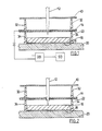
- the cover layer 10, which faces the player is a woven mesh, preferably of a relatively hard polymeric material.
- the pointed projectile 12 must pass relatively unobstructed through this mesh, so the woven strands are preferably of circular cross section and the weave is sufficiently loose to allow relatively easy sideways motion of the strand should the tip of the projectile impinge upon it. Such impingement may slightly deflect the strand or the projectile or both, but such deflection will be minimal.
- the surface of the strand should be sufficiently hard to not be penetrated by the sharp tip of the projectile. In practice, it has been found that a woven mesh of monifilament nylon, a 12.6 mesh by 0.023-inch diameter strand, for example, is very well suited for use as the cover layer.
- the first conductive layer 14, which is spaced away from the cover layer 10 in substantially parallel relationship thereto, is preferably a conductive woven mesh layer.
- a conductive elastomeric foam might also be suitable, but such foams would require frequent replacement, whereas a conductive mesh does not.
- the first conductive layer 14 is a mesh woven of silver plated nylon strands.
- a slightly less favorable alternative is to silver plate a woven nylon mesh, but there may be a tendency during the plating process for the contact points of the crossing strands to become welded or cemented together, which should be avoided for reasons similar to those discussed for the cover layer 10.
- the size of the openings in the mesh of the first conductive layer 14 must be equal to or slightly smaller than the diameter of the generally cylindrically-shaped point of the projectile.
- the conductive mesh we have found that best meets our needs for use in this invention is a 16.6 mesh by 0.0137-inch diameter strand woven monifilament nylon mesh that has been plated with silver.
- the second conductive layer 16 which is spaced away from the first conductive layer 14 in substantially parallel relationship thereto, is substantially impenetrable and is resilient.
- the resilient nature of this surface is principally responsible for the only momentary closing of the electrical circuit comprising the second conductive layer 16, the projectile point 12, which is conductive, and the first conductive layer 14.
- External electrical contact made to the backing board and the first conductive layer is made to an electrical detection device DD and an electrical scoring device SD, neither of which is within the scope of this invention, and of which several have been described in the patent literature and elsewhere.
- the present invention is useful in all designs of targets.
- the two conductive layers extend over the whole of the target and the signal produced when a projectile strikes does not tell what part of the target is struck.
- Other targets are partitioned, such as in the form of a bull's eye with concentric rings, each ring representing a different score.
- at least one of the conductive layers of the present invention must be segmented or partitioned to create a separate electrical circuit for each different scoring region.
- the target board of this invention is well suited to this type of application, as a resilient backing board may be provided having an electrical circuit pattern printed directly thereon to provide many different scoring areas while the conductive mesh layer remains a continuous single contact.
- a conductive resilient backing material 16 is used and each scoring area is backed by a separate piece of this conductive resilient backing material that, in turn, makes electrical contact with the desired array of electrical contacts 18 that may be in the form of individual wire-ends penetrating each section of the conductive backing material or a printed circuit board 20 on the back of the target board in the preferred mode.
- the construction of the target board of this invention is best accomplished by having three matching frame units, superimposed upon one another as shown in FIG. 3.
- the first frame unit 30 is preferably of metal wire construction composed of single or multiple parts and is similar to that used on other high quality dart target boards. Aside from defining for the player the various scoring zones, the primary function of this frame unit in the present invention is to provide a means for securing the mesh cover layer 10 that lies immediately beneath it.
- the second frame unit 32 follows the grid pattern of the target, is aligned with the first frame unit and separates the cover mesh layer 10 from the first conductive layer 14.
- a third frame unit 34 which may be identical to the second, separates the first conductive layer 14 from the second conductive layer 16 and is best made of a non-conducting material. In practice, it has been found that injection molded plastic frames made from duPont DELRIN® acetal resin are well suited for use in this invention as the second and third frame units.
- a circuit printed on a resilient backing board is suitable for use as the second conducting layer in this invention; the backing board providing the suitable rebound for the dart tip without being penetrated thereby, and the printed circuit providing the conductive layer thereon.
- a conductive hard rubber as a conductive rebound surface that comprises the second conductive layer 16.
- multiple conductive hard rubber scoring segments may overlay a circuit pattern 18 printed on a backing board 20, which circuit pattern determines the scoring for each of the segments by connecting each to the electrical circuitry to which the target board is adapted for connecting.
- the simple mechanical contact between the printed circuit 18 and the back of the conductive hard rubber segment 16 provides sufficient electrical contact for transmitting the electrical pulse incident to the closure of the electrical circuit by the impact of the dart tip. In this preferred mode, there is no conductive coating on the resilient surface that might be worn away or damaged by the pointed tip of the dart.
- the conductive hard rubber we have found that best meets our needs for use in this invention is a 115 Durometer, Shore "A", nitrile rubber.
- dart retention is improved by including on the back surface of one of the mesh layers an elastomeric sheet 22, preferably a cellular rubber or elastomeric foam, that, although it is easily penetrated by the pointed tip of the dart point, sufficiently grips the periphery of the dart point to retain the dart in the target board after the dart point has rebounded from the resilient surface.
- This elastomeric sheet is free to deform slightly away from the back surface of the mesh layer 14 as the dart point 12 penetrates the target board (shown in FIG. 2); upon rebound of the dart point, the elastomeric sheet gripping the shaft of the dart point rebounds with it until the sheet again contacts the mesh where it is stopped by the mesh (shown in FIG.
- the elastomeric sheet then in turn stops the motion of the dart point.
- the static friction between the dart point and the elastomeric sheet is easily overcome as the dart is manually extracted from the target board.
- the elastomeric sheet be located on the back of the second mesh layer, the conductive mesh of the first conductive layer 14.
- the elastomeric sheet is usually continuous over the entire area of the target board, being retained with the first conductive layer between two frame units.
- the elastomeric sheet we have found that best meets our needs for use in this invention is a #5100 closed cell sponge rubber.
- Most games utilizing a target board have a target pattern or a scoring pattern that is usually printed on the surface of the target board.
- the front surface or cover layer 10 of the target board of this invention could be printed with such a pattern.
- the mesh comprising the cover layer 10 of the target board is translucent and the space between the cover layer and the first conductive layer is filled with a properly shaped piece of low density open-celled foam 40 of the appropriate color for each area of the target.
- These shapes usually match the openings in the second frame 32 used in the construction of the target board, but a single such opening could contain more than one colored foam element.
- this foam provides target regions of appropriate colors that will not fade or be worn away and which colors are readily visible by the user of the target board, though they are covered by the cover layer mesh 10.
- the openness or low density results in the foam's having little or no effect on the penetration of the dart tip.
- the open-celled foam we have found that best meets our needs for use in this invention is a 20 pores per inch filter foam.
- a support material in the open cavity between the first conductive layer and the second conductive layer may be used advantageously to further enhance dart retention, and is especially valuable in cases where the preferred elastomeric sheet is present.
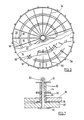
- the deflection of this elastomeric sheet is limited by including between the elastomeric sheet and the conductive hard rubber surface 16 a support structure such as an open celled foam 50 or a honeycomb cellular material 52 with an all cell walls perpendicular to the plane of the target board. The structure of the latter material is most clearly seen in FIG. 6.
- the elastomeric sheet 22 is cut to fit the openings in the frame unit; in this embodiment a support material such as the honeycomb cellular material at this location is not optional but is required to keep the elastomeric sheet 22 in close proximity to the mesh layer 14 upon which its proper functioning depends.
- the honeycomb cellular support material we have found that best meets our needs for use in this invention has a 3/8 inch cell size and is made from impregnated paper with no facing (i.e., each cell is open on both ends).
- the target board of this invention could be used in other activities involving darts or other projectiles.
- the target board may be disassembled and separated, one layer from the other, for servicing either in the field or in a shop or factory location.
- This is made possible by the assembly of the target board from uniform and interchangeable die-cut sheet materials and carefully crafted wire-formed or injection molded frames wherein all of the sheet materials are either clamped between the frame members or totally enclosed by the frame and other sheet members.
- Assembly of the various layers to form the target board is by threaded fasteners and expansion pins 54 (i.e., cotter pins), detail of which is shown in FIG. 7.
Landscapes
- General Engineering & Computer Science (AREA)
- Engineering & Computer Science (AREA)
- Aiming, Guidance, Guns With A Light Source, Armor, Camouflage, And Targets (AREA)
- Ultra Sonic Daignosis Equipment (AREA)
- Power Steering Mechanism (AREA)
- Compositions Of Oxide Ceramics (AREA)
- Toys (AREA)
- General Induction Heating (AREA)
- Paints Or Removers (AREA)
- Inorganic Insulating Materials (AREA)
- Holo Graphy (AREA)
- Chemical And Physical Treatments For Wood And The Like (AREA)
- Indexing, Searching, Synchronizing, And The Amount Of Synchronization Travel Of Record Carriers (AREA)
- Magnetic Record Carriers (AREA)
- Rotational Drive Of Disk (AREA)
- Detergent Compositions (AREA)
- Testing Of Short-Circuits, Discontinuities, Leakage, Or Incorrect Line Connections (AREA)
- Investigating Or Analyzing Materials By The Use Of Electric Means (AREA)
- Testing Of Devices, Machine Parts, Or Other Structures Thereof (AREA)
- Elimination Of Static Electricity (AREA)
- Pinball Game Machines (AREA)
Priority Applications (1)
| Application Number | Priority Date | Filing Date | Title |
|---|---|---|---|
| AT89304039T ATE101708T1 (de) | 1988-04-28 | 1989-04-24 | Wurfpfeilziel mit elektronischer trefferanzeige. |
Applications Claiming Priority (2)
| Application Number | Priority Date | Filing Date | Title |
|---|---|---|---|
| US187215 | 1988-04-28 | ||
| US07/187,215 US4852888A (en) | 1988-04-28 | 1988-04-28 | Electrically scoring dart board |
Publications (3)
| Publication Number | Publication Date |
|---|---|
| EP0339898A2 true EP0339898A2 (de) | 1989-11-02 |
| EP0339898A3 EP0339898A3 (en) | 1990-11-28 |
| EP0339898B1 EP0339898B1 (de) | 1994-02-16 |
Family
ID=22688067
Family Applications (1)
| Application Number | Title | Priority Date | Filing Date |
|---|---|---|---|
| EP89304039A Expired - Lifetime EP0339898B1 (de) | 1988-04-28 | 1989-04-24 | Wurfpfeilziel mit elektronischer Trefferanzeige |
Country Status (15)
| Country | Link |
|---|---|
| US (1) | US4852888A (de) |
| EP (1) | EP0339898B1 (de) |
| JP (1) | JPH01318898A (de) |
| CN (1) | CN1018194B (de) |
| AT (1) | ATE101708T1 (de) |
| AU (1) | AU609685B2 (de) |
| CA (1) | CA1299601C (de) |
| DE (1) | DE68913069T2 (de) |
| DK (1) | DK165805C (de) |
| FI (1) | FI892009L (de) |
| GB (1) | GB2217618B (de) |
| NO (1) | NO168915C (de) |
| NZ (1) | NZ228865A (de) |
| PT (1) | PT90407B (de) |
| ZA (1) | ZA893160B (de) |
Families Citing this family (10)
| Publication number | Priority date | Publication date | Assignee | Title |
|---|---|---|---|---|
| US5486007A (en) * | 1994-05-09 | 1996-01-23 | High Flyte International Ltd. | Automated dart board |
| US5531451A (en) * | 1995-04-14 | 1996-07-02 | Yiu; Chih-Hao | Scoring system for dart games |
| CN100424462C (zh) * | 2001-01-16 | 2008-10-08 | 邵佳沐 | 一种镖靶的磁感应式自动计分方法及自动计分装置 |
| US20040036221A1 (en) * | 2002-08-22 | 2004-02-26 | Martinez Dan L. | Shooting target with electronic zone indicators and method of use |
| CA2417222C (en) * | 2003-01-24 | 2010-07-06 | Optima Global Corporation | Electronic scoring dart board |
| WO2006070875A1 (ja) * | 2004-12-31 | 2006-07-06 | Sega Corporation | ダーツゲーム装置 |
| US9192837B2 (en) | 2012-09-27 | 2015-11-24 | Eastpoint Sports Ltd., Llc | Lawn dart, lawn dart caddy and target |
| CN105056503B (zh) * | 2015-07-28 | 2017-09-22 | 湖南人文科技学院 | 一种训练用的标枪测绘、标定方法 |
| US10443987B2 (en) | 2016-04-21 | 2019-10-15 | Indian Industries, Inc. | Dartboard scoring system |
| US20230266103A1 (en) * | 2022-02-18 | 2023-08-24 | Joseph Anthony Giansante | Precise Electronic Dartboard |
Family Cites Families (5)
| Publication number | Priority date | Publication date | Assignee | Title |
|---|---|---|---|---|
| US3101198A (en) * | 1961-10-04 | 1963-08-20 | James E Williams | Automatically scoring dart board |
| US3275321A (en) * | 1964-01-30 | 1966-09-27 | Gerard M Forest | Target apparatus with discriminating electrical indicator, and projectiles therefor |
| CH522196A (fr) * | 1969-03-27 | 1972-04-30 | Polytronic S A | Cible de tir |
| US4014546A (en) * | 1975-05-29 | 1977-03-29 | Steinkamp Jeffrey H | Scoring apparatus |
| GB1532744A (en) * | 1977-05-30 | 1978-11-22 | Arachnid Inc | Dart board |
-
1988
- 1988-04-28 US US07/187,215 patent/US4852888A/en not_active Expired - Fee Related
- 1988-06-23 GB GB8814990A patent/GB2217618B/en not_active Expired - Lifetime
- 1988-07-25 CA CA000572903A patent/CA1299601C/en not_active Expired - Lifetime
-
1989
- 1989-04-24 EP EP89304039A patent/EP0339898B1/de not_active Expired - Lifetime
- 1989-04-24 DE DE68913069T patent/DE68913069T2/de not_active Expired - Fee Related
- 1989-04-24 AT AT89304039T patent/ATE101708T1/de not_active IP Right Cessation
- 1989-04-24 NZ NZ228865A patent/NZ228865A/en unknown
- 1989-04-27 DK DK205289A patent/DK165805C/da not_active IP Right Cessation
- 1989-04-27 AU AU33825/89A patent/AU609685B2/en not_active Ceased
- 1989-04-27 NO NO891758A patent/NO168915C/no unknown
- 1989-04-27 FI FI892009A patent/FI892009L/fi not_active IP Right Cessation
- 1989-04-28 CN CN89103915A patent/CN1018194B/zh not_active Expired
- 1989-04-28 PT PT90407A patent/PT90407B/pt not_active IP Right Cessation
- 1989-04-28 ZA ZA893160A patent/ZA893160B/xx unknown
- 1989-04-28 JP JP1107954A patent/JPH01318898A/ja active Pending
Also Published As
| Publication number | Publication date |
|---|---|
| DE68913069T2 (de) | 1994-09-01 |
| ZA893160B (en) | 1989-12-27 |
| GB2217618B (en) | 1992-01-02 |
| NO891758L (no) | 1989-10-30 |
| GB8814990D0 (en) | 1988-07-27 |
| CA1299601C (en) | 1992-04-28 |
| CN1018194B (zh) | 1992-09-09 |
| PT90407B (pt) | 1994-05-31 |
| EP0339898A3 (en) | 1990-11-28 |
| AU609685B2 (en) | 1991-05-02 |
| PT90407A (pt) | 1989-11-10 |
| FI892009A0 (fi) | 1989-04-27 |
| DK165805C (da) | 1993-06-21 |
| DE68913069D1 (de) | 1994-03-24 |
| DK165805B (da) | 1993-01-18 |
| NO168915B (no) | 1992-01-06 |
| AU3382589A (en) | 1989-11-02 |
| DK205289A (da) | 1989-10-29 |
| US4852888A (en) | 1989-08-01 |
| NO891758D0 (no) | 1989-04-27 |
| JPH01318898A (ja) | 1989-12-25 |
| ATE101708T1 (de) | 1994-03-15 |
| EP0339898B1 (de) | 1994-02-16 |
| NO168915C (no) | 1992-04-15 |
| GB2217618A (en) | 1989-11-01 |
| FI892009A7 (fi) | 1989-10-29 |
| NZ228865A (en) | 1990-12-21 |
| CN1037662A (zh) | 1989-12-06 |
| FI892009L (fi) | 1989-10-29 |
| DK205289D0 (da) | 1989-04-27 |
Similar Documents
| Publication | Publication Date | Title |
|---|---|---|
| EP0339898B1 (de) | Wurfpfeilziel mit elektronischer Trefferanzeige | |
| US5613685A (en) | Automated dart board | |
| US7604556B2 (en) | Chalk marking projectile | |
| US5613684A (en) | Game platform for magnetic dart game | |
| CA2165923A1 (en) | Impact sensor and target apparatus embodying the same | |
| CA2417222C (en) | Electronic scoring dart board | |
| US2818259A (en) | Dart and target board therefor | |
| US3101198A (en) | Automatically scoring dart board | |
| US5316296A (en) | Shock-absorbing game racket | |
| WO2012055025A1 (en) | Cups for use with an electronic scoring dart board | |
| US4332390A (en) | Target with magnetically-held, dislodgeable indicator | |
| US5188372A (en) | Dart board wire | |
| US5271625A (en) | Flexible point dart | |
| GB2086739A (en) | Target game | |
| MXPA96005465A (es) | Tablero de dardos automatizado | |
| US20020084589A1 (en) | Safe dart and dartboard assembly | |
| JP2732984B2 (ja) | 衝撃吸収部材 | |
| CA2719578A1 (en) | Cladding for use with an electronic scoring dart board | |
| KR100343860B1 (ko) | 장난감총용 타겟박스 | |
| FR2449867A2 (fr) | Jeu du 421 aux des, aux flechettes ou tous autres projectiles | |
| GB2477983A (en) | Counterweighted target device |
Legal Events
| Date | Code | Title | Description |
|---|---|---|---|
| PUAI | Public reference made under article 153(3) epc to a published international application that has entered the european phase |
Free format text: ORIGINAL CODE: 0009012 |
|
| AK | Designated contracting states |
Kind code of ref document: A2 Designated state(s): AT BE CH DE ES FR IT LI LU NL SE |
|
| PUAL | Search report despatched |
Free format text: ORIGINAL CODE: 0009013 |
|
| AK | Designated contracting states |
Kind code of ref document: A3 Designated state(s): AT BE CH DE ES FR IT LI LU NL SE |
|
| 17P | Request for examination filed |
Effective date: 19910422 |
|
| 17Q | First examination report despatched |
Effective date: 19920527 |
|
| GRAA | (expected) grant |
Free format text: ORIGINAL CODE: 0009210 |
|
| AK | Designated contracting states |
Kind code of ref document: B1 Designated state(s): AT BE CH DE ES FR IT LI LU NL SE |
|
| PG25 | Lapsed in a contracting state [announced via postgrant information from national office to epo] |
Ref country code: IT Free format text: LAPSE BECAUSE OF FAILURE TO SUBMIT A TRANSLATION OF THE DESCRIPTION OR TO PAY THE FEE WITHIN THE PRE;WARNING: LAPSES OF ITALIAN PATENTS WITH EFFECTIVE DATE BEFORE 2007 MAY HAVE OCCURRED AT ANY TIME BEFORE 2007. THE CORRECT EFFECTIVE DATE MAY BE DIFFERENT FROM THE ONE RECORDED.SCRIBED TIME-LIMIT Effective date: 19940216 Ref country code: AT Effective date: 19940216 Ref country code: CH Effective date: 19940216 Ref country code: ES Free format text: THE PATENT HAS BEEN ANNULLED BY A DECISION OF A NATIONAL AUTHORITY Effective date: 19940216 Ref country code: BE Effective date: 19940216 Ref country code: NL Effective date: 19940216 Ref country code: LI Effective date: 19940216 Ref country code: SE Effective date: 19940216 |
|
| REF | Corresponds to: |
Ref document number: 101708 Country of ref document: AT Date of ref document: 19940315 Kind code of ref document: T |
|
| REF | Corresponds to: |
Ref document number: 68913069 Country of ref document: DE Date of ref document: 19940324 |
|
| PG25 | Lapsed in a contracting state [announced via postgrant information from national office to epo] |
Ref country code: LU Free format text: LAPSE BECAUSE OF NON-PAYMENT OF DUE FEES Effective date: 19940430 |
|
| REG | Reference to a national code |
Ref country code: CH Ref legal event code: PL |
|
| ET | Fr: translation filed | ||
| NLV1 | Nl: lapsed or annulled due to failure to fulfill the requirements of art. 29p and 29m of the patents act | ||
| PLBE | No opposition filed within time limit |
Free format text: ORIGINAL CODE: 0009261 |
|
| STAA | Information on the status of an ep patent application or granted ep patent |
Free format text: STATUS: NO OPPOSITION FILED WITHIN TIME LIMIT |
|
| 26N | No opposition filed | ||
| PGFP | Annual fee paid to national office [announced via postgrant information from national office to epo] |
Ref country code: FR Payment date: 19950411 Year of fee payment: 7 |
|
| PGFP | Annual fee paid to national office [announced via postgrant information from national office to epo] |
Ref country code: DE Payment date: 19950421 Year of fee payment: 7 |
|
| PG25 | Lapsed in a contracting state [announced via postgrant information from national office to epo] |
Ref country code: FR Effective date: 19961227 |
|
| PG25 | Lapsed in a contracting state [announced via postgrant information from national office to epo] |
Ref country code: DE Effective date: 19970101 |
|
| REG | Reference to a national code |
Ref country code: FR Ref legal event code: ST |