EP0339809B1 - An asynchronous time division network - Google Patents
An asynchronous time division network Download PDFInfo
- Publication number
- EP0339809B1 EP0339809B1 EP89303252A EP89303252A EP0339809B1 EP 0339809 B1 EP0339809 B1 EP 0339809B1 EP 89303252 A EP89303252 A EP 89303252A EP 89303252 A EP89303252 A EP 89303252A EP 0339809 B1 EP0339809 B1 EP 0339809B1
- Authority
- EP
- European Patent Office
- Prior art keywords
- switch
- packet
- queue
- time division
- data
- Prior art date
- Legal status (The legal status is an assumption and is not a legal conclusion. Google has not performed a legal analysis and makes no representation as to the accuracy of the status listed.)
- Expired - Lifetime
Links
Images


Classifications
-
- H—ELECTRICITY
- H04—ELECTRIC COMMUNICATION TECHNIQUE
- H04L—TRANSMISSION OF DIGITAL INFORMATION, e.g. TELEGRAPHIC COMMUNICATION
- H04L12/00—Data switching networks
- H04L12/54—Store-and-forward switching systems
- H04L12/56—Packet switching systems
- H04L12/5601—Transfer mode dependent, e.g. ATM
-
- H—ELECTRICITY
- H04—ELECTRIC COMMUNICATION TECHNIQUE
- H04L—TRANSMISSION OF DIGITAL INFORMATION, e.g. TELEGRAPHIC COMMUNICATION
- H04L49/00—Packet switching elements
- H04L49/10—Packet switching elements characterised by the switching fabric construction
- H04L49/104—Asynchronous transfer mode [ATM] switching fabrics
- H04L49/105—ATM switching elements
- H04L49/106—ATM switching elements using space switching, e.g. crossbar or matrix
-
- H—ELECTRICITY
- H04—ELECTRIC COMMUNICATION TECHNIQUE
- H04L—TRANSMISSION OF DIGITAL INFORMATION, e.g. TELEGRAPHIC COMMUNICATION
- H04L49/00—Packet switching elements
- H04L49/15—Interconnection of switching modules
- H04L49/1553—Interconnection of ATM switching modules, e.g. ATM switching fabrics
- H04L49/1576—Crossbar or matrix
-
- H—ELECTRICITY
- H04—ELECTRIC COMMUNICATION TECHNIQUE
- H04L—TRANSMISSION OF DIGITAL INFORMATION, e.g. TELEGRAPHIC COMMUNICATION
- H04L12/00—Data switching networks
- H04L12/54—Store-and-forward switching systems
- H04L12/56—Packet switching systems
- H04L12/5601—Transfer mode dependent, e.g. ATM
- H04L2012/5638—Services, e.g. multimedia, GOS, QOS
- H04L2012/5646—Cell characteristics, e.g. loss, delay, jitter, sequence integrity
- H04L2012/5651—Priority, marking, classes
-
- H—ELECTRICITY
- H04—ELECTRIC COMMUNICATION TECHNIQUE
- H04L—TRANSMISSION OF DIGITAL INFORMATION, e.g. TELEGRAPHIC COMMUNICATION
- H04L12/00—Data switching networks
- H04L12/54—Store-and-forward switching systems
- H04L12/56—Packet switching systems
- H04L12/5601—Transfer mode dependent, e.g. ATM
- H04L2012/5678—Traffic aspects, e.g. arbitration, load balancing, smoothing, buffer management
- H04L2012/5681—Buffer or queue management
Definitions
- the present invention relates to an asynchronous time division network wherein data is divided into fixed length packets which are transmitted by way of high rate bearers.
- circuit switched TDM multiplex In a known form of circuit switched TDM multiplex a particular circuit is identified from all others by imposing a frame and counting the slots from the start of the frame. This implies that the circuit rate is a fixed and exact proportion of the bearer rate; therefore the system is synchronous. In such systems small differences in rate (plesiochronous operation) can be handled by either occasionally deleting or repeating a sample carried in a slot or by providing a bearer nominally above the synchronous rate and padding the frame to fit.
- the network carries packets for two basic types of virtual circuit. These are STREAM circuits equivalent to a conventional circuit switched service, and BURST circuits carrying bursty data. In the latter case it may be assumed that an embedded protocol is provided to acknowledge 'data packets' (corresponding to a contiguous group of switch packets) and providing a repeat facility if 'data packets' are incorrectly received. Also, in the case, relatively long queueing delays are acceptable. If the bearers and ports are loaded with up to, say, 55% of STREAM traffic and STREAM packets are given first priority of access then BURST services can be offered access using the remaining capacity. In this way much higher loadings may be achieved, at least on the output ports.
- Providing first priority access to STREAM services in a single plane switch will give some improvement; however, if a single queue is used at the input ports and the packet at the head of the queue is a BURST packet, following STREAM packets will be blocked. A greater improvement is achieved by providing two input queues, one for STREAM packets (with first priority access) and the other for BURST packets. The BURST packet queue can also be made longer to allow for transient conditions. For a multi-stage switch a further modest improvement can be achieved by routing STREAM and BURST data through separate switch planes. This improvement results because the loading on inter-stage bearers is substantially reduced. Almost all the loss then occurs at the access point to the common ouput port bearer. In this case also the loss on STREAM services is negligibly small, almost all loss occurs on BURST packets.
- a queuing algorithm is therefore required to take note of packets further back from the head of the queue. The further back the algorithm looks, the higher the achievable occupancy of the destination bearer.
- a network in which data is divided into fixed length packets, the network comprising a switching matrix having a plurality of input ports and a plurality of output ports arranged in columns and means is provided for routing each data packet from an input port to a defined output port by way of a plurality of individually addressed switching nodes, each node being provided with queuing means and each queuing means in each output column is given priority according to a predetermined priority arbitration scheme.
- an aim of the present invention is to provide an asynchronous time division network which includes an efficient queuing means over those known in the prior art.
- an asynchronous time division network in which data is divided into fixed length packets which are transmitted by way of high rate bearers, the network comprising a switching matrix having a plurality of input ports and a plurality of output ports, arranged in columns, and means is provided for routing each data packet from an input port to a defined output port by way of plurality of individually addressed switching nodes, each node being provided with queuing means, and each queuing means in each output column is given priority according to a predetermined priority arbitration scheme characterised in that priority test means is arranged so that each queuing means in each output column of the switching matrix is tested and priority is given to the first queuing means tested which holds more than one packet.
- a virtual circuit is a non-physical circuit between source and destination represented by recognition of the packet header at each node and a predicted statisticated allowance for the channel characteristics on bearers along the route.
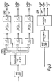
- the switching element is shown in Figure 1, and is an 8 x 8 array with at least a two-packet queue (Q) at each crosspoint (Xpt).
- the elements will also provide, for example, a sixteen-packet input queue (I/PQ).
- I/PQ sixteen-packet input queue
- Each input line will allow for a reverse direction slot to indicate the Input Queue Full condition.
- the element carries out the following operations in parallel on each port: Test of the input queue status; 'Queue Full' (QF) response if full or load queue if not full. Test crosspoint queue addressed by leading packet of input queue; if not full transfer packet to crosspoint queue.
- QF Quality of Service
- Each queue provides three indications to the polling logic: Single cell present, More than one cell present, No cells present.
- the polling sequence is up to two cycles of the input ports.
- the first queue addressed with more than one cell present is accepted immediately and the polling sequence is stopped.
- the first queue addressed with a single cell present is accepted and the polling sequence is stopped.
- the polling sequence will start from the position where the last sequence stopped thus ensuring equality of access for all ports.
- Figure 2 shows a typical configuration of known form for a 512 port switch, composed of a number of switch elements as shown in Figure 1, interconnected to form a switching matrix.
- a line terminator in which a translator translates the label on incoming packets received on the port input logic.
- the label is translated into a new label for the outgoing packet.
- the translator also provides routing digits in the form of an address which are accepted by successive switching stages.
- the translator also selects one of three switch planes, and connections to the planes are made by way of respective output logic circuits to the respective switch input queue and queue full logic of the addressed switch element.
- contention logic receives the data from the switching planes which is passed through a speed-match first in first out buffer before dispatch by way of the port output logic.
- the LABEL field in the header of an incoming packet is used to address a TRANSLATOR Figure 2, the output of which is a new LABEL to be used in the packet on the destination bearer, and a series of address fields for routing the packet through the switch.
- a TRANSLATOR Figure 2 the output of which is a new LABEL to be used in the packet on the destination bearer, and a series of address fields for routing the packet through the switch.
- fields A3 through A5 will uniquely identify the destination bearer whilst A1 and A2 provide for alternative paths for the virtual circuit through the switch.
- the LABEL and ADDRESS fields are set up by the control system when a virtual circuit is established.
- the TRANSLATOR also holds a field identifying one of three switch planes (0, 1, 2) Figure 3. The planes are provided both for traffic and security reasons.
- the output from the port logic is a packet in a standard format recognised by the switch elements.
- the transmission line is slotted and a slot may be in use (busy) or unused (free).
- a BUSY/FREE (B/F) bit is therefore needed at the front of the header.
- B/F BUSY/FREE
- SS SLOT START
- the following 2-bits are used to transmit a QUEUE FULL (QF) indication in the reverse direction on the same line. These lines therefore have bi-directional ports at each end.
- the QUEUE FULL bit is buffered by a half bit either side to allow for timing tolerances.
- the next 3-bits contains the address (A1) for the output port of the first stage of the switch and is followed by A2 through A5.
- A1 the address for the output port of the first stage of the switch
- A2 the address for the output port of the first stage of the switch
- A2 the address for the output port of the first stage of the switch
- A5 the 16 bit LABEL which is not required by the switch
- SN 2-bit SEQUENCE NUMBER
- the sequence number is used at the terminal to recognise the loss of a packet.
- P PARITY bit
- the P bit completes the header but, after the 128-bit DATA field, A ⁇ is added. This is the input port of the first stage switch element and, together with A1 to A5, will allow the input port to be identified at the output port.
- This information may be used by the control system to identify 'bad' paths through the switch and may result in a change of the plane value in the TRANSLATOR output. All the data from A1 at the start of the packet to A ⁇ at the end are entered into the input packet queue of the switch element if the queue is not full.
- the first 3 bits (A1) in the leading packet of the switch element input queue are read out and used to address the relevant crosspoint queue. If the queue is not full the following fields (A2 to A ⁇ ) are loaded into the queue.
- a queue status field is set according to the resultant status, which may be QUEUE EMPTY, ONE PACKET,>ONE PACKET or QUEUE FULL (for a 2-packet queue where >ONE PACKET corresponds to QUEUE FULL, the latter is used).
- the SS bit followed by BUSY is transmitted on the switch element output port.
- the QF bit is read from the 'output' port and the crosspoint queue status bits in the column are asynchronously polled. Polling starts from the row after the last row sent and first priority is given to a queue with the status >ONE PACKET or QUEUE FULL. If the incoming QF bit was zero then the first packet in the selected crosspoint queue is transmitted and the port address field (A1 for the first stage) is appended to the end of the transmission.
- the switch output port logic inputs are received from all switch planes.
- the planes are given a fixed priority order thus the final stage switch element of a lower priority plane may receive a 'QF' indication which in this case means that a packet from a higher priority has been selected.
- the switch address fields are redundant in the transmitted packet, therefore this packet is shorter, implying that the in-switch packets are clocked at a higher rate.
- Speed matching is achieved via a FIFO and the packet comprises, for example, a 3-bit SLOT SYNCHRONISATION field which, unlike the 1-bit field in the switch, is used to determine slot start.
- the 16-bit LABEL which is used at the terminating end of the link to determine the virtual circuit, followed by the 2-bit SN, a 3-bit CRC and the 128-bit data field. In this case a free slot would be identified by the all-zeroes code in the LABEL field.
- At least two switch planes are needed to carry STREAM or BURST type virtual circuits with the higher priority given to STREAM. If one of the two planes failed then it could be possible to offer all traffic to the one remaining plane.
- An integrated solution using three planes with descending order of priority at the output ports of the switch offers a satisfactory solution.
- An error message may then be sent to the control including the fields A0 to A5 which identify the source port and the path through the switch.
- a control decision can then be taken to change the plane for that virtual circuit by changing the PLANE field in the incoming port TRANSLATOR.
- the Parity bit and CRC are provided only over the header.
- Errors in the data field for STREAM connections may not affect performance as much as deletion of the packet, e.g. a single error over 16 speech samples would probably not be noticed but loss of 16 samples would result in a noticeable 'click'.
- the terminal protocol for BURST connection includes an embedded CRC.
Abstract
Description
- The present invention relates to an asynchronous time division network wherein data is divided into fixed length packets which are transmitted by way of high rate bearers.
- In a known form of circuit switched TDM multiplex a particular circuit is identified from all others by imposing a frame and counting the slots from the start of the frame. This implies that the circuit rate is a fixed and exact proportion of the bearer rate; therefore the system is synchronous. In such systems small differences in rate (plesiochronous operation) can be handled by either occasionally deleting or repeating a sample carried in a slot or by providing a bearer nominally above the synchronous rate and padding the frame to fit.
- In a known asynchronous time division network discussed in US Patent No. 4,491,945 a technique of rotating the destination address is used, so that the two most significant bits of the address are always presented to the next succeeding switch node.
- For an asynchronous time division network there is no frame and each packet carries its own identification and, provided the bearer rate is sufficient to give a very low probability of packets being lost due to queue overflow, there need not be a synchronous relationship.
- In this type of network modest sized switch elements can be used, for example 8 x 8, but a disadvantage is that queues are needed at each switch element input port.
- The network carries packets for two basic types of virtual circuit. These are STREAM circuits equivalent to a conventional circuit switched service, and BURST circuits carrying bursty data. In the latter case it may be assumed that an embedded protocol is provided to acknowledge 'data packets' (corresponding to a contiguous group of switch packets) and providing a repeat facility if 'data packets' are incorrectly received. Also, in the case, relatively long queueing delays are acceptable. If the bearers and ports are loaded with up to, say, 55% of STREAM traffic and STREAM packets are given first priority of access then BURST services can be offered access using the remaining capacity. In this way much higher loadings may be achieved, at least on the output ports. Providing first priority access to STREAM services in a single plane switch will give some improvement; however, if a single queue is used at the input ports and the packet at the head of the queue is a BURST packet, following STREAM packets will be blocked. A greater improvement is achieved by providing two input queues, one for STREAM packets (with first priority access) and the other for BURST packets. The BURST packet queue can also be made longer to allow for transient conditions. For a multi-stage switch a further modest improvement can be achieved by routing STREAM and BURST data through separate switch planes. This improvement results because the loading on inter-stage bearers is substantially reduced. Almost all the loss then occurs at the access point to the common ouput port bearer. In this case also the loss on STREAM services is negligibly small, almost all loss occurs on BURST packets.
- The above solution suffers from the disadvantage that, when more than one input port wishes to send a packet to the same output port at the same time only one can succeed, thus packets further back in the queue may be blocked from free output ports. This problem can be resolved by providing a very short queue at each crosspoint of the switch matrix. Packets are then loaded from the input queue into the relevant crosspoint queue and output bearers will normally have one or more packets waiting to be transmitted on that bearer. The combination of a two plane switch with two packet crosspoint queue permits loadings of more than 80% assuming 70% STREAM and 30% BURST traffic.
- A queuing algorithm is therefore required to take note of packets further back from the head of the queue. The further back the algorithm looks, the higher the achievable occupancy of the destination bearer.
- In PCT Patent Application WO-A-8602510 is disclosed a network in which data is divided into fixed length packets, the network comprising a switching matrix having a plurality of input ports and a plurality of output ports arranged in columns and means is provided for routing each data packet from an input port to a defined output port by way of a plurality of individually addressed switching nodes, each node being provided with queuing means and each queuing means in each output column is given priority according to a predetermined priority arbitration scheme.
- Accordingly, an aim of the present invention is to provide an asynchronous time division network which includes an efficient queuing means over those known in the prior art.
- According to the present invention there is provided an asynchronous time division network in which data is divided into fixed length packets which are transmitted by way of high rate bearers, the network comprising a switching matrix having a plurality of input ports and a plurality of output ports, arranged in columns, and means is provided for routing each data packet from an input port to a defined output port by way of plurality of individually addressed switching nodes, each node being provided with queuing means, and each queuing means in each output column is given priority according to a predetermined priority arbitration scheme characterised in that priority test means is arranged so that each queuing means in each output column of the switching matrix is tested and priority is given to the first queuing means tested which holds more than one packet.
- An embodiment of the present invention will now be described with reference to the accompanying drawings wherein:-
- Figure 1 shows an 8 x 8 switching element,
- Figure 2 shows a typical configuration for a 512 port switch,
- Figure 3 shows an asynchronous time division digital line terminator,
- Figure 4 shows the sequential packet formats for a 5-stage switch.
- Connections through the network are established as virtual circuits using by-path signalling, for example CCITT
No 7 signalling. A virtual circuit is a non-physical circuit between source and destination represented by recognition of the packet header at each node and a predicted statisticated allowance for the channel characteristics on bearers along the route. - The switching element is shown in Figure 1, and is an 8 x 8 array with at least a two-packet queue (Q) at each crosspoint (Xpt). The elements will also provide, for example, a sixteen-packet input queue (I/PQ). Each input line will allow for a reverse direction slot to indicate the Input Queue Full condition.
- The element carries out the following operations in parallel on each port:
Test of the input queue status; 'Queue Full' (QF) response if full or load queue if not full.
Test crosspoint queue addressed by leading packet of input queue; if not full transfer packet to crosspoint queue. - Test crosspoint queues in each output column of the switch matrix starting from the row after the last one transmitted from in that column. First priority is given to the first crosspoint queue tested holding more than on packet, else the first crosspoint queue holding one packet. This process must be very rapid, a gap is allowed in the output format of 2 bit periods to complete this test which must therefore be asynchronous. This gap corresponds to the period allowed for the 'Queue Full' response from the next stage. The packet is transmitted if the following input queue is not full, and the 3-bit address of the output port is added to the end of the packet.
- Each queue provides three indications to the polling logic:
Single cell present,
More than one cell present,
No cells present. - In each case a cell being input to the queue is included and a cell being output from the queue is not included.
- The polling sequence is up to two cycles of the input ports.
- The first queue addressed with more than one cell present is accepted immediately and the polling sequence is stopped.
- After one cycle of the ports the first queue addressed with a single cell present is accepted and the polling sequence is stopped.
- After two cycles of the ports, if no queue is accepted the 'true' indication will be transmitted in the new slot.
- The polling sequence will start from the position where the last sequence stopped thus ensuring equality of access for all ports.
- Figure 2 shows a typical configuration of known form for a 512 port switch, composed of a number of switch elements as shown in Figure 1, interconnected to form a switching matrix.
- Referring to Figure 3, a line terminator is shown, in which a translator translates the label on incoming packets received on the port input logic. The label is translated into a new label for the outgoing packet. The translator also provides routing digits in the form of an address which are accepted by successive switching stages. The translator also selects one of three switch planes, and connections to the planes are made by way of respective output logic circuits to the respective switch input queue and queue full logic of the addressed switch element.
- In the reverse direction, contention logic receives the data from the switching planes which is passed through a speed-match first in first out buffer before dispatch by way of the port output logic.
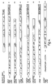
- The sequential packet formats for a 5-stage switch are shown in Figure 4.
- The LABEL field in the header of an incoming packet is used to address a TRANSLATOR Figure 2, the output of which is a new LABEL to be used in the packet on the destination bearer, and a series of address fields for routing the packet through the switch. For a 5-stage switch, five 3-bit ADDRESS fields are needed, A1 through A5. Using a conventional switch configuration, fields A3 through A5 will uniquely identify the destination bearer whilst A1 and A2 provide for alternative paths for the virtual circuit through the switch. The LABEL and ADDRESS fields are set up by the control system when a virtual circuit is established. The TRANSLATOR also holds a field identifying one of three switch planes (0, 1, 2) Figure 3. The planes are provided both for traffic and security reasons.
- The output from the port logic is a packet in a standard format recognised by the switch elements. The transmission line is slotted and a slot may be in use (busy) or unused (free). A BUSY/FREE (B/F) bit is therefore needed at the front of the header. In addition a SLOT START (SS) bit is provided. This bit contains a multi-slot pattern which is used, not to synchronise the slot since a separate slot start clock would be provided, but to confirm the start position as an extra precaution.
- The following 2-bits are used to transmit a QUEUE FULL (QF) indication in the reverse direction on the same line. These lines therefore have bi-directional ports at each end. The QUEUE FULL bit is buffered by a half bit either side to allow for timing tolerances.
- The next 3-bits contains the address (A1) for the output port of the first stage of the switch and is followed by A2 through A5. Next is the 16 bit LABEL which is not required by the switch, followed by a 2-bit SEQUENCE NUMBER (SN). The sequence number is used at the terminal to recognise the loss of a packet. This is followed by a PARITY bit (P) over the address fields, label and SN. The P bit completes the header but, after the 128-bit DATA field, A⌀ is added. This is the input port of the first stage switch element and, together with A1 to A5, will allow the input port to be identified at the output port. This information may be used by the control system to identify 'bad' paths through the switch and may result in a change of the plane value in the TRANSLATOR output. All the data from A1 at the start of the packet to A⌀ at the end are entered into the input packet queue of the switch element if the queue is not full.
- In parallel with the above operation, the first 3 bits (A1) in the leading packet of the switch element input queue are read out and used to address the relevant crosspoint queue. If the queue is not full the following fields (A2 to A⌀) are loaded into the queue. A queue status field is set according to the resultant status, which may be QUEUE EMPTY, ONE PACKET,>ONE PACKET or QUEUE FULL (for a 2-packet queue where >ONE PACKET corresponds to QUEUE FULL, the latter is used).
- In parallel with the above operations and if at least one of the crosspoint queue status fields in the column is not QUEUE EMPTY, the SS bit followed by BUSY is transmitted on the switch element output port. During the next two bits two parallel operations take place. The QF bit is read from the 'output' port and the crosspoint queue status bits in the column are asynchronously polled. Polling starts from the row after the last row sent and first priority is given to a queue with the status >ONE PACKET or QUEUE FULL. If the incoming QF bit was zero then the first packet in the selected crosspoint queue is transmitted and the port address field (A1 for the first stage) is appended to the end of the transmission.
- The above operations occur simultaneously at all input and output ports of the switch element.
- At the switch output port logic, inputs are received from all switch planes. The planes are given a fixed priority order thus the final stage switch element of a lower priority plane may receive a 'QF' indication which in this case means that a packet from a higher priority has been selected.
- The switch address fields are redundant in the transmitted packet, therefore this packet is shorter, implying that the in-switch packets are clocked at a higher rate. Speed matching is achieved via a FIFO and the packet comprises, for example, a 3-bit SLOT SYNCHRONISATION field which, unlike the 1-bit field in the switch, is used to determine slot start. This is followed by the 16-bit LABEL which is used at the terminating end of the link to determine the virtual circuit, followed by the 2-bit SN, a 3-bit CRC and the 128-bit data field. In this case a free slot would be identified by the all-zeroes code in the LABEL field.
- At least two switch planes are needed to carry STREAM or BURST type virtual circuits with the higher priority given to STREAM. If one of the two planes failed then it could be possible to offer all traffic to the one remaining plane. An integrated solution using three planes with descending order of priority at the output ports of the switch offers a satisfactory solution. Using the parity check over the header (including free slots), errors can be detected in the output port logic. An error message may then be sent to the control including the fields A0 to A5 which identify the source port and the path through the switch. A control decision can then be taken to change the plane for that virtual circuit by changing the PLANE field in the incoming port TRANSLATOR. The Parity bit and CRC are provided only over the header.
- Errors in the data in the header will result in a packet being sent to the wrong destination, which can have serious effects on a connection.
- Errors in the data field for STREAM connections may not affect performance as much as deletion of the packet, e.g. a single error over 16 speech samples would probably not be noticed but loss of 16 samples would result in a noticeable 'click'. The terminal protocol for BURST connection includes an embedded CRC.
- The check over the header only is adequate for performance analysis if it is assumed that packets are transmitted serially within and external to the switch, so that the data field and header both use the same hardware.
- The above description is one example of implementing the invention, and is not intended to limit the scope of the invention. It will be readily understood for example that alternative forms of signalling can be used, different queuing techniques may be used, and different switching matrix sizes may be used.
Claims (6)
- An asynchronous time division network in which data is divided into fixed length packets which are transmitted by way of high rate bearers, the network comprising a switching matrix having a plurality of input ports (INCOMING PORTS) and a plurality of output ports (OUTGOING PORTS), arranged in columns, and means is provided for routing each data packet from an input port to a defined output port by way of a plurality of individually addressed switching nodes (SWITCH ELEMENT), each node (SWITCH ELEMENT) being provided with queuing means (I/PQ, Xpt Q), and each queuing means (I/PQ, Xpt Q) in each output column is given priority according to a predetermined priority arbitration scheme characterised in that priority test means is arranged so that each queuing means (I/PQ, Xpt Q) in each output column of the switching matrix is tested and priority is given to the first queuing means (I/PQ, Xpt Q) tested which holds more than one packet.
- An asynchronous time division network as claimed in Claim 1, wherein a translator (TRANSLATOR) at each input port (INCOMING PORT) is arranged to translate a label appended to an incoming packet of data, into a new label appended to the outgoing packet of data.
- An asynchronous time division network as claimed in Claim 2, wherein the translator (TRANSLATOR) is arranged to generate routing digits in the form of an address acceptable to successive switching stages (SWITCH ELEMENT).
- An asynchronous time division network as claimed in Claim 3, wherein the translator (TRANSLATOR) is arranged to select one of three switch planes (SWITCH PLANE 0, SWITCH PLANE1, SWITCH PLANE 2) and connections are made by way of respective output logic circuits and respective switch input queue and queue full, logic circuits.
- An asynchronous time division network as claimed in Claim 4, including a contention logic circuit (CONTENTION LOGIC) and a speed match first-in first-out store (SPEED-MATCH FIFO) arranged to pass data received from the switching planes (SWITCH PLANE 0, SWITCH PLANE 1, SWITCH PLANE 2) to the respective output port.
- An asynchronous time division network as claimed in Claim 1 or 5 wherein each queuing means (I/PQ, Xpt Q) is provided with a status indicator which is polled and priority is given to a queue having more than one packet of data or a full queue.
Applications Claiming Priority (2)
| Application Number | Priority Date | Filing Date | Title |
|---|---|---|---|
| GB888810094A GB8810094D0 (en) | 1988-04-28 | 1988-04-28 | Asychronous time division network |
| GB8810094 | 1988-04-28 |
Publications (3)
| Publication Number | Publication Date |
|---|---|
| EP0339809A2 EP0339809A2 (en) | 1989-11-02 |
| EP0339809A3 EP0339809A3 (en) | 1991-05-02 |
| EP0339809B1 true EP0339809B1 (en) | 1994-10-26 |
Family
ID=10636044
Family Applications (1)
| Application Number | Title | Priority Date | Filing Date |
|---|---|---|---|
| EP89303252A Expired - Lifetime EP0339809B1 (en) | 1988-04-28 | 1989-04-03 | An asynchronous time division network |
Country Status (7)
| Country | Link |
|---|---|
| US (1) | US5199028A (en) |
| EP (1) | EP0339809B1 (en) |
| JP (1) | JPH0229136A (en) |
| AT (1) | ATE113431T1 (en) |
| DE (1) | DE68918981T2 (en) |
| ES (1) | ES2061979T3 (en) |
| GB (2) | GB8810094D0 (en) |
Families Citing this family (20)
| Publication number | Priority date | Publication date | Assignee | Title |
|---|---|---|---|---|
| CA2015514C (en) * | 1989-08-22 | 1996-08-06 | Mitsuru Tsuboi | Packet switching system having bus matrix switch |
| NL9000765A (en) * | 1990-04-02 | 1991-11-01 | Apt Nederland | DIGITAL DATA PACKAGE MODULE FOR ALLOCATING EMPTY PACKAGES TO CROSSROAD SWITCH. |
| FR2708817B1 (en) * | 1993-07-30 | 1995-09-08 | Boyer Pierre | Time slot allocation systems and multiplexers with one of these time slot allocation systems. |
| US5402416A (en) * | 1994-01-05 | 1995-03-28 | International Business Machines Corporation | Method and system for buffer occupancy reduction in packet switch network |
| EP0665701A1 (en) * | 1994-01-26 | 1995-08-02 | Siemens Aktiengesellschaft | Method for monitoring the connection paths in a digital time division multiplex exchange |
| US5530157A (en) * | 1995-02-16 | 1996-06-25 | Scios Nova Inc. | Anti-inflammatory benzoic acid derivatives |
| US5923654A (en) * | 1996-04-25 | 1999-07-13 | Compaq Computer Corp. | Network switch that includes a plurality of shared packet buffers |
| US5859853A (en) * | 1996-06-21 | 1999-01-12 | International Business Machines Corporation | Adaptive packet training |
| US6298070B1 (en) | 1998-05-07 | 2001-10-02 | International Business Machines Corporation | Packet training with an adjustable optimum number of packets |
| US6876678B1 (en) | 1999-02-04 | 2005-04-05 | Cisco Technology, Inc. | Time division multiplexing method and apparatus for asynchronous data stream |
| US7012895B1 (en) | 2000-11-17 | 2006-03-14 | University Of Kentucky Research Foundation | Packet-switching network with symmetrical topology and method of routing packets |
| US7106738B2 (en) * | 2001-04-06 | 2006-09-12 | Erlang Technologies, Inc. | Method and apparatus for high speed packet switching using train packet queuing and providing high scalability |
| US20030169731A1 (en) * | 2002-03-08 | 2003-09-11 | Wickeraad John Alan | Crossbar switch with data suspension |
| US7158512B1 (en) | 2002-04-01 | 2007-01-02 | P-Cube Ltd. | System and method for scheduling a cross-bar |
| US8937964B2 (en) * | 2002-06-27 | 2015-01-20 | Tellabs Operations, Inc. | Apparatus and method to switch packets using a switch fabric with memory |
| US20040148391A1 (en) * | 2003-01-11 | 2004-07-29 | Lake Shannon M | Cognitive network |
| EP1521496A1 (en) * | 2003-09-30 | 2005-04-06 | Alcatel | Universal exchange, method for performing a switching task, input unit, output unit and connection unit |
| EP1521497A3 (en) * | 2003-09-30 | 2006-05-31 | Alcatel | Universal exchange, method for performing a switching task, input unit, output unit and connection unit |
| JP4568021B2 (en) * | 2004-04-05 | 2010-10-27 | 株式会社日立製作所 | Computer system that operates the command multiple number monitoring control system |
| US7747734B2 (en) * | 2006-03-29 | 2010-06-29 | International Business Machines Corporation | Apparatus, system, and method for error assessment over a communication link |
Family Cites Families (9)
| Publication number | Priority date | Publication date | Assignee | Title |
|---|---|---|---|---|
| JPS479221Y1 (en) * | 1968-01-10 | 1972-04-07 | ||
| US4512011A (en) * | 1982-11-01 | 1985-04-16 | At&T Bell Laboratories | Duplicated network arrays and control facilities for packet switching |
| JPS6056129U (en) * | 1983-09-27 | 1985-04-19 | 村田機械株式会社 | plate loader |
| JPS6128741U (en) * | 1984-07-26 | 1986-02-20 | 村田機械株式会社 | Plate separation equipment |
| KR900006793B1 (en) * | 1984-10-18 | 1990-09-21 | 휴우즈 에어크라프트 캄파니 | Packet switched multiple queue nxm switch mode and processing method |
| US4797882A (en) * | 1985-10-02 | 1989-01-10 | American Telephone And Telegraph Company, At&T Bell Laboratories | Mesh-based switching network |
| JPH0324519Y2 (en) * | 1986-10-14 | 1991-05-28 | ||
| US4864558A (en) * | 1986-11-29 | 1989-09-05 | Nippon Telegraph And Telephone Corporation | Self-routing switch |
| US4817082A (en) * | 1987-03-09 | 1989-03-28 | American Telephone And Telegraph Company, At&T Bell Laboratories | Crosspoint switching system using control rings with fast token circulation |
-
1988
- 1988-04-28 GB GB888810094A patent/GB8810094D0/en active Pending
-
1989
- 1989-04-03 AT AT89303252T patent/ATE113431T1/en not_active IP Right Cessation
- 1989-04-03 EP EP89303252A patent/EP0339809B1/en not_active Expired - Lifetime
- 1989-04-03 DE DE68918981T patent/DE68918981T2/en not_active Expired - Lifetime
- 1989-04-03 ES ES89303252T patent/ES2061979T3/en not_active Expired - Lifetime
- 1989-04-11 US US07/336,158 patent/US5199028A/en not_active Expired - Lifetime
- 1989-04-11 GB GB8908074A patent/GB2218305B/en not_active Expired - Lifetime
- 1989-04-27 JP JP1106129A patent/JPH0229136A/en active Pending
Also Published As
| Publication number | Publication date |
|---|---|
| GB2218305A (en) | 1989-11-08 |
| DE68918981D1 (en) | 1994-12-01 |
| GB8908074D0 (en) | 1989-05-24 |
| US5199028A (en) | 1993-03-30 |
| ES2061979T3 (en) | 1994-12-16 |
| ATE113431T1 (en) | 1994-11-15 |
| GB2218305B (en) | 1992-08-19 |
| DE68918981T2 (en) | 1995-03-02 |
| EP0339809A3 (en) | 1991-05-02 |
| JPH0229136A (en) | 1990-01-31 |
| EP0339809A2 (en) | 1989-11-02 |
| GB8810094D0 (en) | 1988-06-02 |
Similar Documents
| Publication | Publication Date | Title |
|---|---|---|
| EP0339809B1 (en) | An asynchronous time division network | |
| EP0201252B1 (en) | Packet switch trunk circuit queueing arrangement | |
| EP0276349B1 (en) | Apparatus for switching information between channels for synchronous information traffic and asynchronous data packets | |
| EP0312628B1 (en) | High-speed modular switching apparatus for circuit and packet switched traffic | |
| EP0516042B1 (en) | ATM cell error processing system | |
| US5166930A (en) | Data channel scheduling discipline arrangement and method | |
| AU703227B2 (en) | Connectionless communication system | |
| USRE34305E (en) | Switching system and method of construction thereof | |
| EP0886939B1 (en) | Efficient output-request packet switch and method | |
| CA1254982A (en) | Method of and switch for switching information | |
| EP0112831B1 (en) | Fast packet switch | |
| JP2788577B2 (en) | Frame conversion method and apparatus | |
| US4797880A (en) | Non-blocking, self-routing packet switch | |
| EP0581486A2 (en) | High bandwidth packet switch | |
| EP1051001A2 (en) | Controlled access ATM switch | |
| EP0498408B1 (en) | ATM exchange system with management cells | |
| WO1988004870A1 (en) | Enhanced efficiency batcher-banyan packet switch | |
| US20040141510A1 (en) | CAM based system and method for re-sequencing data packets | |
| US4891802A (en) | Method of and circuit arrangement for controlling a switching network in a switching system | |
| US4969149A (en) | Switching network for a switching system | |
| EP0683949B1 (en) | A method for handling redundant switching planes in packet switches and a switch for carrying out the method | |
| US5164937A (en) | Packet concentrator and packet switching system | |
| EP0339735B1 (en) | Junction switch for packet switching | |
| EP0243563A1 (en) | Non coded information and companion data switching mechanism | |
| EP0477242B1 (en) | Data switching nodes |
Legal Events
| Date | Code | Title | Description |
|---|---|---|---|
| PUAI | Public reference made under article 153(3) epc to a published international application that has entered the european phase |
Free format text: ORIGINAL CODE: 0009012 |
|
| AK | Designated contracting states |
Kind code of ref document: A2 Designated state(s): AT BE CH DE ES FR GR IT LI LU NL SE |
|
| PUAL | Search report despatched |
Free format text: ORIGINAL CODE: 0009013 |
|
| AK | Designated contracting states |
Kind code of ref document: A3 Designated state(s): AT BE CH DE ES FR GR IT LI LU NL SE |
|
| 17P | Request for examination filed |
Effective date: 19910830 |
|
| 17Q | First examination report despatched |
Effective date: 19930730 |
|
| GRAA | (expected) grant |
Free format text: ORIGINAL CODE: 0009210 |
|
| AK | Designated contracting states |
Kind code of ref document: B1 Designated state(s): AT BE CH DE ES FR GR IT LI LU NL SE |
|
| PG25 | Lapsed in a contracting state [announced via postgrant information from national office to epo] |
Ref country code: AT Effective date: 19941026 Ref country code: CH Effective date: 19941026 Ref country code: BE Effective date: 19941026 Ref country code: LI Effective date: 19941026 Ref country code: NL Effective date: 19941026 Ref country code: GR Free format text: LAPSE BECAUSE OF FAILURE TO SUBMIT A TRANSLATION OF THE DESCRIPTION OR TO PAY THE FEE WITHIN THE PRESCRIBED TIME-LIMIT Effective date: 19941026 |
|
| REF | Corresponds to: |
Ref document number: 113431 Country of ref document: AT Date of ref document: 19941115 Kind code of ref document: T |
|
| ITF | It: translation for a ep patent filed |
Owner name: JACOBACCI CASETTA & PERANI S.P.A. |
|
| ET | Fr: translation filed | ||
| REF | Corresponds to: |
Ref document number: 68918981 Country of ref document: DE Date of ref document: 19941201 |
|
| REG | Reference to a national code |
Ref country code: ES Ref legal event code: FG2A Ref document number: 2061979 Country of ref document: ES Kind code of ref document: T3 |
|
| EAL | Se: european patent in force in sweden |
Ref document number: 89303252.4 |
|
| REG | Reference to a national code |
Ref country code: CH Ref legal event code: PL |
|
| PG25 | Lapsed in a contracting state [announced via postgrant information from national office to epo] |
Ref country code: SE Effective date: 19950404 |
|
| NLV1 | Nl: lapsed or annulled due to failure to fulfill the requirements of art. 29p and 29m of the patents act | ||
| PG25 | Lapsed in a contracting state [announced via postgrant information from national office to epo] |
Ref country code: LU Free format text: LAPSE BECAUSE OF NON-PAYMENT OF DUE FEES Effective date: 19950430 |
|
| PLBE | No opposition filed within time limit |
Free format text: ORIGINAL CODE: 0009261 |
|
| STAA | Information on the status of an ep patent application or granted ep patent |
Free format text: STATUS: NO OPPOSITION FILED WITHIN TIME LIMIT |
|
| 26N | No opposition filed | ||
| EUG | Se: european patent has lapsed |
Ref document number: 89303252.4 |
|
| PGFP | Annual fee paid to national office [announced via postgrant information from national office to epo] |
Ref country code: ES Payment date: 20020417 Year of fee payment: 14 |
|
| PG25 | Lapsed in a contracting state [announced via postgrant information from national office to epo] |
Ref country code: ES Free format text: LAPSE BECAUSE OF NON-PAYMENT OF DUE FEES Effective date: 20030404 |
|
| REG | Reference to a national code |
Ref country code: FR Ref legal event code: CD Ref country code: FR Ref legal event code: TP |
|
| REG | Reference to a national code |
Ref country code: ES Ref legal event code: FD2A Effective date: 20030404 |
|
| REG | Reference to a national code |
Ref country code: FR Ref legal event code: TP |
|
| PGFP | Annual fee paid to national office [announced via postgrant information from national office to epo] |
Ref country code: DE Payment date: 20080602 Year of fee payment: 20 |
|
| PGFP | Annual fee paid to national office [announced via postgrant information from national office to epo] |
Ref country code: IT Payment date: 20080429 Year of fee payment: 20 |
|
| PGFP | Annual fee paid to national office [announced via postgrant information from national office to epo] |
Ref country code: FR Payment date: 20080417 Year of fee payment: 20 |