EP0339730A1 - Round baler with variable bale chamber and sledge assembly - Google Patents
Round baler with variable bale chamber and sledge assembly Download PDFInfo
- Publication number
- EP0339730A1 EP0339730A1 EP89201036A EP89201036A EP0339730A1 EP 0339730 A1 EP0339730 A1 EP 0339730A1 EP 89201036 A EP89201036 A EP 89201036A EP 89201036 A EP89201036 A EP 89201036A EP 0339730 A1 EP0339730 A1 EP 0339730A1
- Authority
- EP
- European Patent Office
- Prior art keywords
- bale
- apron
- round baler
- sledge assembly
- chamber
- Prior art date
- Legal status (The legal status is an assumption and is not a legal conclusion. Google has not performed a legal analysis and makes no representation as to the accuracy of the status listed.)
- Granted
Links
- 230000015572 biosynthetic process Effects 0.000 claims description 7
- 239000000463 material Substances 0.000 description 12
- 230000007246 mechanism Effects 0.000 description 1
- 239000004460 silage Substances 0.000 description 1
- 239000010902 straw Substances 0.000 description 1
Images

Classifications
-
- A—HUMAN NECESSITIES
- A01—AGRICULTURE; FORESTRY; ANIMAL HUSBANDRY; HUNTING; TRAPPING; FISHING
- A01F—PROCESSING OF HARVESTED PRODUCE; HAY OR STRAW PRESSES; DEVICES FOR STORING AGRICULTURAL OR HORTICULTURAL PRODUCE
- A01F15/00—Baling presses for straw, hay or the like
- A01F15/07—Rotobalers, i.e. machines for forming cylindrical bales by winding and pressing
- A01F2015/077—Pressing chamber formed by belts and rollers
-
- A—HUMAN NECESSITIES
- A01—AGRICULTURE; FORESTRY; ANIMAL HUSBANDRY; HUNTING; TRAPPING; FISHING
- A01F—PROCESSING OF HARVESTED PRODUCE; HAY OR STRAW PRESSES; DEVICES FOR STORING AGRICULTURAL OR HORTICULTURAL PRODUCE
- A01F15/00—Baling presses for straw, hay or the like
- A01F15/07—Rotobalers, i.e. machines for forming cylindrical bales by winding and pressing
- A01F2015/079—Sledge for rollers of the pressing chamber
-
- A—HUMAN NECESSITIES
- A01—AGRICULTURE; FORESTRY; ANIMAL HUSBANDRY; HUNTING; TRAPPING; FISHING
- A01F—PROCESSING OF HARVESTED PRODUCE; HAY OR STRAW PRESSES; DEVICES FOR STORING AGRICULTURAL OR HORTICULTURAL PRODUCE
- A01F15/00—Baling presses for straw, hay or the like
- A01F15/07—Rotobalers, i.e. machines for forming cylindrical bales by winding and pressing
- A01F2015/0795—Pressing chamber with variable volume
Definitions
- This invention relates generally to agricultural balers and, in particular, to such balers typically referred to as "round balers" which form cylindrical bales of crop material.
- bale forming elements Three basic types of bale forming elements have been used in round balers. These are chain and slat aprons, belt aprons and rollers. Each type of bale forming element has advantages and disadvantages. For example, an advantage of chain and slat aprons is that they are capable of starting bale formation in almost all crop conditions but a disadvantage of these aprons is that they often form bales with rough outer surfaces. An advantage of belt aprons is that they form bales with smooth outer surfaces but a disadvantage of belt aprons is that they have bale starting problems in certain crop conditions. Rollers also have the advantage of forming bales with smooth outer surfaces but they have a disadvantage of resulting in losses of crop material through the gaps between adjacent rollers.
- EP-A-0.296.665 discloses a round baler utilizing a combination of bale forming rollers and a belt apron.
- the rollers are fixedly positioned and cooperate with the belt apron to define a generally D-shaped bale starting chamber.
- Said rollers form a front wall of the starting chamber, and the belt apron has an expandable course that forms a rear wall of the starting chamber.
- the round baler disclosed in EP-A-0.296.665 functions adequately in hay and when making full size bales, it encounters problems operating in straw and silage and when making less than full size bales.
- the D-shaped starting chamber results in the generation of fines and causes the less than full size bales to be out-of-round and have lower than desireable density and poor appearance.
- the present invention provides a round baler having : - a main frame; - a tailgate pivotally connected to the main frame, and - apron means movably supported on the main frame and the tailgate and having an expandable inner course; said baler being characterized in that it also has a sledge assembly mounted on the main frame; said sledge assembly comprising at least one roller and being cooperable with the inner course of the apron means to determine a bale forming chamber therebetween and said sledge assembly and said inner course, in first positions, defining a bale starting chamber and being movable toward full bale positions as a bale is being formed in said chamber.
- the sledge assembly comprises a plurality of rollers which cooperate with the apron inner course to define the bale starting chamber.
- the sledge assembly also comprises idler means engaging the apron for maintaining the apron in close proximity to one roller of the plurality of rollers during movement of the sledge assembly between the bale starting and full bale positions.
- the apron inner course forms a rear wall of the bale starting chamber and the plurality of rollers forms a front wall of the bale starting chamber.
- the apron may comprise a plurality of belts supported on guide rolls which are rotatably mounted on the tailgate and on a drive roll which is rotatably mounted on the main frame.
- a round baler 10 includes a main frame 12 supported by a pair of wheels 14.
- a tongue 16 is provided on the forward portion of the main frame 12 for connection to a tractor (not shown).
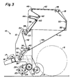
- a tailgate 18 is pivotally connected to the main frame 12 by stub shafts 20 so that the tailgate 18 may be closed as shown in Fig. 1 and opened as shown in Fig. 3.
- a conventional pickup 22 is mounted on the main frame 12 by a pair of brackets 24 and is supported by a pair of wheels (not shown).
- the pickup 22 includes a plurality of fingers or tines 26 movable in a predetermined path to lift crop material from the ground and deliver it rearwardly toward a floor roll 28 which is rotatably mounted on the main frame 12.
- a sledge assembly 29 includes a plurality of rollers 30, 32, 34 extending transversely of the main frame 12 in an arcuate arrangement and journalled at the ends thereof in a pair of arcuately shaped arms 36.
- the arms 36 are pivotally mounted inside the main frame 12 on stub shafts 38 for permitting movement of the sledge assembly 29 between a bale starting position shown in Fig. 1 and a full bale position shown in Fig. 2.
- the rollers 30, 32, 34 are driven in a clockwise direction as indicated in Fig. 1 by conventional means (for example, chains and sprockets or gears) connected with a drive shaft 17 which is adapted for connection to the PTO of a tractor (not shown).
- a stripper roll 39 is located adjacent roller 30 and is driven in a clockwise direction, as viewed in Fig. 1, to strip crop material from the roller 30.
- An idler roller 40 is carried by the arms 36 for movement in an arcuate path when the sledge assembly 29 moves between its bale starting and full bale positions.
- the idler roller 40 is freely rotatable.
- An apron 41 includes a plurality of belts 42 supported on guide rolls 44, 46, 48, 50, 52 which are rotatably mounted in the tailgate 18 and on a drive roll 54 which is rotatably mounted in the main frame 12.
- the belts 42 pass between the roller 34 and the idler roller 40, they are in engagement with only the idler roller 40 but the roller 34 is located in close proximity to the belts 42 to strip crop material from the belts 42.
- Further conventional means (not shown) are connected with the drive shaft 17 to provide rotation of the drive roll 54 in a direction which causes movement of the belts 42 along the path indicated in Fig. 1 when starting a bale.
- An additional guide roll 55 in the main frame 12 ensures proper driving engagement between the belts 42 and the drive roll 54.
- Another pair of arms 56 are pivotally mounted on the main frame 12 by a cross shaft 58 for movement between inner and outer positions shown in Figs. 1 and 2, respectively.
- Arms 56 carry additional guide rolls 60 and 62 for the belts 42.
- Resilient means (not shown) are provided to normally urge the arms 56 toward their inner positions while resisting movement thereof from their inner positions to their outer positions.
- an inner course 42a of the apron belts 42 extending between the guide roll 52 and the idler roller 40 cooperates with the rollers 30, 32, 34 of the sledge assembly 29 to define a bale starting chamber 64.
- the apron inner course 42a forms a rear wall of the chamber 64 while the rollers 30, 32, 34 form a front wall of the chamber 64.
- the floor roll 28 is disposed in the bottom of the chamber 64 between the front and rear walls thereof.
- the roller 30 is spaced from the floor roll 28 to form a throat or inlet 66 for the chamber 64, and the arms 56 will be urged into their inner positions shown in Fig. 1.
- the pickup tines 26 lift crop material from the ground and feed it into the bale starting chamber 64 via the throat 66.
- the crop material is carried rearwardly by the floor roll 28 into engagement with the apron inner course 42a which carries it upwardly and forwardly into engagement with the rollers 30, 32, 34.
- the crop material is coiled in a counterclockwise direction as viewed in Fig. 1 to start a bale core C.
- Continued feeding of crop material into the chamber 64 by the pickup tines 26 causes the apron inner course 42a of the belts 42 to expand in length around a portion of the bale core C as the diameter thereof increases.
- the arms 56 rotate from their inner position shown in Fig.
- the tailgate 18 is opened by conventional means (for example, hydraulic cylinders) and the bale B is ejected as shown in Fig. 3. Subsequent closing of the tailgate 18 returns the apron inner course 42a to the location shown in Fig. 1 since the arms 56 are returned to their inner position shown in Fig. 1.
- the round baler 10 is now ready to form another bale.
- sledge assembly 29 moves from its bale starting position of Fig. 1 to its full bale position of Fig. 2.
- This movement of the sledge assembly 29 causes the idler roller 40 to move in an arcuate path while maintaining the apron belts 42 in close proximity to the roller 34, thereby allowing the roller 34 to strip crop material from the apron belts 42.
- the idler roller 40 thus prevents the loss of crop material between the roller 34 and the belts 42 during formation of the bale B.
- the sledge assembly 29 is pushed outwardly toward its full bale position during bale formation and is pulled inwardly toward its bale starting position during bale ejection without utilizing any additional mechanisms.
- apron 41 consists of a pair of chains connected together at spaced intervals by transverse slats, and the idler roller 40 is replaced by a pair of idler sprockets engaged with the chains.
- the guide rolls 44, 46, 48, 50, 52, 55, 60 and 62 would be replaced with guide sprockets for engaging the apron chains, and the drive roll 54 would be replaced with drive sprockets.
Landscapes
- Life Sciences & Earth Sciences (AREA)
- Environmental Sciences (AREA)
- Harvester Elements (AREA)
- Storage Of Harvested Produce (AREA)
Abstract
Description
- This invention relates generally to agricultural balers and, in particular, to such balers typically referred to as "round balers" which form cylindrical bales of crop material.
- Three basic types of bale forming elements have been used in round balers. These are chain and slat aprons, belt aprons and rollers. Each type of bale forming element has advantages and disadvantages. For example, an advantage of chain and slat aprons is that they are capable of starting bale formation in almost all crop conditions but a disadvantage of these aprons is that they often form bales with rough outer surfaces. An advantage of belt aprons is that they form bales with smooth outer surfaces but a disadvantage of belt aprons is that they have bale starting problems in certain crop conditions. Rollers also have the advantage of forming bales with smooth outer surfaces but they have a disadvantage of resulting in losses of crop material through the gaps between adjacent rollers.
EP-A-0.296.665 discloses a round baler utilizing a combination of bale forming rollers and a belt apron. In this round baler, the rollers are fixedly positioned and cooperate with the belt apron to define a generally D-shaped bale starting chamber. Said rollers form a front wall of the starting chamber, and the belt apron has an expandable course that forms a rear wall of the starting chamber. While the round baler disclosed in EP-A-0.296.665 functions adequately in hay and when making full size bales, it encounters problems operating in straw and silage and when making less than full size bales. For example, the D-shaped starting chamber results in the generation of fines and causes the less than full size bales to be out-of-round and have lower than desireable density and poor appearance. - It is an object of the present invention to provide a round baler which incorporates as many advantages as possible of the three basic types of bale forming elements while minimizing the disadvantages thereof. It is also an object of the present invention to provide a round baler which overcomes the aforementioned problems encountered by the round baler disclosed in EP-A-0.296.665.
- The present invention provides a round baler having :
- a main frame;
- a tailgate pivotally connected to the main frame, and
- apron means movably supported on the main frame and the tailgate and having an expandable inner course;
said baler being characterized in that it also has a sledge assembly mounted on the main frame; said sledge assembly comprising at least one roller and being cooperable with the inner course of the apron means to determine a bale forming chamber therebetween and said sledge assembly and said inner course, in first positions, defining a bale starting chamber and being movable toward full bale positions as a bale is being formed in said chamber. - In the preferred embodiment of the round baler, the sledge assembly comprises a plurality of rollers which cooperate with the apron inner course to define the bale starting chamber. The sledge assembly also comprises idler means engaging the apron for maintaining the apron in close proximity to one roller of the plurality of rollers during movement of the sledge assembly between the bale starting and full bale positions. The apron inner course forms a rear wall of the bale starting chamber and the plurality of rollers forms a front wall of the bale starting chamber. The apron may comprise a plurality of belts supported on guide rolls which are rotatably mounted on the tailgate and on a drive roll which is rotatably mounted on the main frame.
- A round baler embodying the present invention will now be described in greater detail by way of example with reference to the accompanying drawings, in which :
- Fig. 1 is a side elevational view of a round baler according to the preferred embodiment of the present invention at the start of bale formation;
- Fig. 2 is another side elevational view of the round baler of Fig. 1 at the completion of bale formation; and
- Fig. 3 is a further side elevational view of the round baler of Fig. 1 during bale ejection.
- Referring to Figs. 1 and 2, a
round baler 10 according to the preferred embodiment of the present invention includes amain frame 12 supported by a pair ofwheels 14. Atongue 16 is provided on the forward portion of themain frame 12 for connection to a tractor (not shown). Atailgate 18 is pivotally connected to themain frame 12 bystub shafts 20 so that thetailgate 18 may be closed as shown in Fig. 1 and opened as shown in Fig. 3. Aconventional pickup 22 is mounted on themain frame 12 by a pair ofbrackets 24 and is supported by a pair of wheels (not shown). Thepickup 22 includes a plurality of fingers ortines 26 movable in a predetermined path to lift crop material from the ground and deliver it rearwardly toward afloor roll 28 which is rotatably mounted on themain frame 12. - In accordance with the present invention, a
sledge assembly 29 includes a plurality ofrollers main frame 12 in an arcuate arrangement and journalled at the ends thereof in a pair of arcuately shapedarms 36. Thearms 36 are pivotally mounted inside themain frame 12 onstub shafts 38 for permitting movement of thesledge assembly 29 between a bale starting position shown in Fig. 1 and a full bale position shown in Fig. 2. Therollers stripper roll 39 is locatedadjacent roller 30 and is driven in a clockwise direction, as viewed in Fig. 1, to strip crop material from theroller 30. Anidler roller 40 is carried by thearms 36 for movement in an arcuate path when thesledge assembly 29 moves between its bale starting and full bale positions. Theidler roller 40 is freely rotatable. - An
apron 41 includes a plurality ofbelts 42 supported onguide rolls tailgate 18 and on adrive roll 54 which is rotatably mounted in themain frame 12. Although thebelts 42 pass between theroller 34 and theidler roller 40, they are in engagement with only theidler roller 40 but theroller 34 is located in close proximity to thebelts 42 to strip crop material from thebelts 42. Further conventional means (not shown) are connected with the drive shaft 17 to provide rotation of thedrive roll 54 in a direction which causes movement of thebelts 42 along the path indicated in Fig. 1 when starting a bale. An additional guide roll 55 in themain frame 12 ensures proper driving engagement between thebelts 42 and thedrive roll 54. Another pair ofarms 56 are pivotally mounted on themain frame 12 by across shaft 58 for movement between inner and outer positions shown in Figs. 1 and 2, respectively.Arms 56 carryadditional guide rolls belts 42. Resilient means (not shown) are provided to normally urge thearms 56 toward their inner positions while resisting movement thereof from their inner positions to their outer positions. - When the
round baler 10 is in the condition shown in Fig. 1 with thetailgate 18 closed, an inner course 42a of theapron belts 42 extending between theguide roll 52 and theidler roller 40 cooperates with therollers sledge assembly 29 to define abale starting chamber 64. The apron inner course 42a forms a rear wall of thechamber 64 while therollers chamber 64. Thefloor roll 28 is disposed in the bottom of thechamber 64 between the front and rear walls thereof. Theroller 30 is spaced from thefloor roll 28 to form a throat or inlet 66 for thechamber 64, and thearms 56 will be urged into their inner positions shown in Fig. 1. - As the
round baler 10 is towed across a field by a tractor (not shown), the pickup tines 26 lift crop material from the ground and feed it into thebale starting chamber 64 via thethroat 66. The crop material is carried rearwardly by thefloor roll 28 into engagement with the apron inner course 42a which carries it upwardly and forwardly into engagement with therollers chamber 64 by thepickup tines 26 causes the apron inner course 42a of thebelts 42 to expand in length around a portion of the bale core C as the diameter thereof increases. Thearms 56 rotate from their inner position shown in Fig. 1 toward their outer position shown in Fig. 2 to permit such expansion of the apron inner course 42a. When a full sized bale B has been formed and then wrapped with a suitable material such as twine or net, thetailgate 18 is opened by conventional means (for example, hydraulic cylinders) and the bale B is ejected as shown in Fig. 3. Subsequent closing of thetailgate 18 returns the apron inner course 42a to the location shown in Fig. 1 since thearms 56 are returned to their inner position shown in Fig. 1. Theround baler 10 is now ready to form another bale. - It will be understood that during formation of the bale B,
sledge assembly 29 moves from its bale starting position of Fig. 1 to its full bale position of Fig. 2. This movement of thesledge assembly 29 causes theidler roller 40 to move in an arcuate path while maintaining theapron belts 42 in close proximity to theroller 34, thereby allowing theroller 34 to strip crop material from theapron belts 42. Theidler roller 40 thus prevents the loss of crop material between theroller 34 and thebelts 42 during formation of the bale B. Thesledge assembly 29 is pushed outwardly toward its full bale position during bale formation and is pulled inwardly toward its bale starting position during bale ejection without utilizing any additional mechanisms. - In an alternative embodiment of the
round baler 10,apron 41 consists of a pair of chains connected together at spaced intervals by transverse slats, and theidler roller 40 is replaced by a pair of idler sprockets engaged with the chains. Also in this alternative embodiment, theguide rolls drive roll 54 would be replaced with drive sprockets.
Claims (15)
- a main frame (12);
- a tailgate (18) pivotally connected to the main frame (12), and
- apron means (41) movably supported on the main frame (12) and the tailgate (18) and having an expandable inner course (42a), and
characterized in that the baler (10) also has
- a sledge assembly (29) mounted on the main frame (12); said sledge assembly (29) comprising at least one roller (34) and being cooperable with the inner course (42a) of the apron means (41) to determine a bale forming chamber (64) therebetween and said sledge assembly (29) and said inner course (42a), in first positions, defining a bale starting chamber and being movable toward full bale positions as a bale (B) is being formed in said chamber (64).
- the apron means (41) comprise a pair of transversely spaced apart chains connected together at spaced intervals by transverse slats, said chains being supported on guide sprockets which are rotatably mounted on the tailgate (18) and on drive sprockets which are rotatably mounted on the main frame (12), and
- the idler means (40) are formed by a pair of idler sprockets disposed on the sledge assembly (29) to be engaged by the apron chains.
Applications Claiming Priority (4)
| Application Number | Priority Date | Filing Date | Title |
|---|---|---|---|
| US18654288A | 1988-04-27 | 1988-04-27 | |
| US186542 | 1988-04-27 | ||
| US186984 | 1988-04-27 | ||
| US07/186,984 US4870812A (en) | 1988-04-27 | 1988-04-27 | Round baler with variable bale chamber |
Publications (2)
| Publication Number | Publication Date |
|---|---|
| EP0339730A1 true EP0339730A1 (en) | 1989-11-02 |
| EP0339730B1 EP0339730B1 (en) | 1993-04-21 |
Family
ID=26882188
Family Applications (1)
| Application Number | Title | Priority Date | Filing Date |
|---|---|---|---|
| EP19890201036 Expired - Lifetime EP0339730B1 (en) | 1988-04-27 | 1989-04-21 | Round baler with variable bale chamber and sledge assembly |
Country Status (2)
| Country | Link |
|---|---|
| EP (1) | EP0339730B1 (en) |
| DE (1) | DE68906068T2 (en) |
Cited By (4)
| Publication number | Priority date | Publication date | Assignee | Title |
|---|---|---|---|---|
| FR2750006A1 (en) * | 1996-06-21 | 1997-12-26 | Claas Ohg | ROUND BALL PRESS |
| FR2767020A1 (en) * | 1997-08-07 | 1999-02-12 | Gallignani Spa | Agricultural cylindrical baler |
| FR2767635A1 (en) * | 1997-09-03 | 1999-03-05 | Proofunique France Sa | Cylindrical bale press for agricultural products e.g. hay |
| DE10063121A1 (en) * | 2000-12-18 | 2002-06-20 | Deere & Co | Round baler |
Families Citing this family (5)
| Publication number | Priority date | Publication date | Assignee | Title |
|---|---|---|---|---|
| DE3941707A1 (en) * | 1989-12-18 | 1991-06-20 | Claas Ohg | ROUND BALL PRESS FOR COLLAR HARVEST |
| IT1277868B1 (en) * | 1995-07-24 | 1997-11-12 | Antonio Feraboli | ROUND BALER FOR COLLECTING AND FORMING CYLINDRICAL BALES OF FORAGE OR STRAW, OF THE VARIABLE CHAMBER TYPE, WITH CHAMBER |
| DE29706544U1 (en) | 1997-04-11 | 1997-06-05 | Greenland Geldrop B.V., Geldrop | Round baler |
| DE102004027895A1 (en) | 2004-06-09 | 2006-01-05 | Claas Selbstfahrende Erntemaschinen Gmbh | Ball filing system |
| DE102016001588A1 (en) * | 2016-02-11 | 2017-08-17 | Pöttinger Landtechnik Gmbh | baler |
Citations (4)
| Publication number | Priority date | Publication date | Assignee | Title |
|---|---|---|---|---|
| FR2460099A1 (en) * | 1979-07-04 | 1981-01-23 | Rivierre Casalis Sa | Fodder strip delivery mechanism into round baler - has shaping chamber formed by pick=up, feed and-support roller and run of endless cloth |
| GB2150492A (en) * | 1983-12-01 | 1985-07-03 | Texas Industries Inc | Balers |
| EP0161726A2 (en) * | 1984-05-18 | 1985-11-21 | Ford New Holland N.V. | Round baler |
| EP0228944B1 (en) * | 1985-12-20 | 1991-01-16 | Rivierre Casalis | Apparatus for forming round bales of an agricultural produce in a rotobaler |
-
1989
- 1989-04-21 EP EP19890201036 patent/EP0339730B1/en not_active Expired - Lifetime
- 1989-04-21 DE DE1989606068 patent/DE68906068T2/en not_active Expired - Lifetime
Patent Citations (4)
| Publication number | Priority date | Publication date | Assignee | Title |
|---|---|---|---|---|
| FR2460099A1 (en) * | 1979-07-04 | 1981-01-23 | Rivierre Casalis Sa | Fodder strip delivery mechanism into round baler - has shaping chamber formed by pick=up, feed and-support roller and run of endless cloth |
| GB2150492A (en) * | 1983-12-01 | 1985-07-03 | Texas Industries Inc | Balers |
| EP0161726A2 (en) * | 1984-05-18 | 1985-11-21 | Ford New Holland N.V. | Round baler |
| EP0228944B1 (en) * | 1985-12-20 | 1991-01-16 | Rivierre Casalis | Apparatus for forming round bales of an agricultural produce in a rotobaler |
Cited By (6)
| Publication number | Priority date | Publication date | Assignee | Title |
|---|---|---|---|---|
| FR2750006A1 (en) * | 1996-06-21 | 1997-12-26 | Claas Ohg | ROUND BALL PRESS |
| DE19624718A1 (en) * | 1996-06-21 | 1998-01-08 | Claas Ohg | Round especially agricultural baler with bale chamber |
| DE19624718C2 (en) * | 1996-06-21 | 2002-10-31 | Claas Kgaa Mbh | Round baler |
| FR2767020A1 (en) * | 1997-08-07 | 1999-02-12 | Gallignani Spa | Agricultural cylindrical baler |
| FR2767635A1 (en) * | 1997-09-03 | 1999-03-05 | Proofunique France Sa | Cylindrical bale press for agricultural products e.g. hay |
| DE10063121A1 (en) * | 2000-12-18 | 2002-06-20 | Deere & Co | Round baler |
Also Published As
| Publication number | Publication date |
|---|---|
| DE68906068T2 (en) | 1993-08-12 |
| EP0339730B1 (en) | 1993-04-21 |
| DE68906068D1 (en) | 1993-05-27 |
Similar Documents
| Publication | Publication Date | Title |
|---|---|---|
| US4870812A (en) | Round baler with variable bale chamber | |
| US4956968A (en) | Round baler with mechanism for dispensing wrapping material | |
| EP0754403B1 (en) | Pick-up apparatus for a crop collecting device | |
| EP0965263B1 (en) | Round bale wrapping apparatus | |
| US6651418B1 (en) | Modular pickup, stuffer, and rotor | |
| EP0954959B1 (en) | Round bale forming apparatus | |
| US4212149A (en) | Crop baling machines | |
| US5581973A (en) | Apparatus for making round bales | |
| EP0082170B1 (en) | Method and apparatus for forming bales | |
| US4597254A (en) | Continuous roll baler | |
| US5191833A (en) | Roll stripping apparatus for round baler | |
| CA2028022C (en) | Bale wrapping apparatus for round balers | |
| EP2777382B1 (en) | Baler rear shield mechanism | |
| EP0432830B1 (en) | Bale wrapping apparatus for round balers | |
| US5598690A (en) | Tailgate latching apparatus for a round baler | |
| EP0339730B1 (en) | Round baler with variable bale chamber and sledge assembly | |
| US5913805A (en) | Trash baffle for round baler apparatus | |
| US4899651A (en) | Apron tensioning system for round balers | |
| EP0235787B1 (en) | Machine for forming cylindrical bales of crop | |
| US6722100B1 (en) | Simplified wrap material dispenser for crop bales | |
| EP0766912B1 (en) | Apparatus and method for wrapping round bales | |
| US5419108A (en) | Method of forming a segmented round bale | |
| EP0296665B1 (en) | Round baler with rollers and belts | |
| US6094899A (en) | Separating arrangement for adjacent belts in a round baler | |
| US5044272A (en) | Round baler with rollers and belts |
Legal Events
| Date | Code | Title | Description |
|---|---|---|---|
| PUAI | Public reference made under article 153(3) epc to a published international application that has entered the european phase |
Free format text: ORIGINAL CODE: 0009012 |
|
| 17P | Request for examination filed |
Effective date: 19890421 |
|
| AK | Designated contracting states |
Kind code of ref document: A1 Designated state(s): DE FR GB |
|
| 17Q | First examination report despatched |
Effective date: 19910423 |
|
| GRAA | (expected) grant |
Free format text: ORIGINAL CODE: 0009210 |
|
| AK | Designated contracting states |
Kind code of ref document: B1 Designated state(s): DE FR GB |
|
| REF | Corresponds to: |
Ref document number: 68906068 Country of ref document: DE Date of ref document: 19930527 |
|
| RAP2 | Party data changed (patent owner data changed or rights of a patent transferred) |
Owner name: NEW HOLLAND BELGIUM N.V. |
|
| ET | Fr: translation filed | ||
| PLBE | No opposition filed within time limit |
Free format text: ORIGINAL CODE: 0009261 |
|
| STAA | Information on the status of an ep patent application or granted ep patent |
Free format text: STATUS: NO OPPOSITION FILED WITHIN TIME LIMIT |
|
| 26N | No opposition filed | ||
| REG | Reference to a national code |
Ref country code: GB Ref legal event code: IF02 |
|
| REG | Reference to a national code |
Ref country code: FR Ref legal event code: CD |
|
| PGFP | Annual fee paid to national office [announced via postgrant information from national office to epo] |
Ref country code: DE Payment date: 20080415 Year of fee payment: 20 |
|
| PGFP | Annual fee paid to national office [announced via postgrant information from national office to epo] |
Ref country code: FR Payment date: 20080407 Year of fee payment: 20 |
|
| PGFP | Annual fee paid to national office [announced via postgrant information from national office to epo] |
Ref country code: GB Payment date: 20080410 Year of fee payment: 20 |
|
| REG | Reference to a national code |
Ref country code: GB Ref legal event code: PE20 Expiry date: 20090420 |
|
| PG25 | Lapsed in a contracting state [announced via postgrant information from national office to epo] |
Ref country code: GB Free format text: LAPSE BECAUSE OF EXPIRATION OF PROTECTION Effective date: 20090420 |