EP0338969B1 - Switch gear cubicle with a low tension switch apparatus - Google Patents
Switch gear cubicle with a low tension switch apparatus Download PDFInfo
- Publication number
- EP0338969B1 EP0338969B1 EP89730100A EP89730100A EP0338969B1 EP 0338969 B1 EP0338969 B1 EP 0338969B1 EP 89730100 A EP89730100 A EP 89730100A EP 89730100 A EP89730100 A EP 89730100A EP 0338969 B1 EP0338969 B1 EP 0338969B1
- Authority
- EP
- European Patent Office
- Prior art keywords
- locking lever
- switching
- accordance
- locking
- switching device
- Prior art date
- Legal status (The legal status is an assumption and is not a legal conclusion. Google has not performed a legal analysis and makes no representation as to the accuracy of the status listed.)
- Expired - Lifetime
Links
- 238000009434 installation Methods 0.000 claims abstract description 7
- 230000005484 gravity Effects 0.000 claims abstract description 5
- 238000003780 insertion Methods 0.000 claims description 5
- 230000037431 insertion Effects 0.000 claims description 5
- 239000002184 metal Substances 0.000 claims description 4
- 238000005452 bending Methods 0.000 claims description 2
- 230000004308 accommodation Effects 0.000 claims 1
- 230000000717 retained effect Effects 0.000 claims 1
- 238000000034 method Methods 0.000 description 3
- 238000004080 punching Methods 0.000 description 3
- 230000006835 compression Effects 0.000 description 1
- 238000007906 compression Methods 0.000 description 1
- 230000008878 coupling Effects 0.000 description 1
- 238000010168 coupling process Methods 0.000 description 1
- 238000005859 coupling reaction Methods 0.000 description 1
- 238000006073 displacement reaction Methods 0.000 description 1
- 230000000694 effects Effects 0.000 description 1
- 239000007789 gas Substances 0.000 description 1
- 239000000463 material Substances 0.000 description 1
- 230000007704 transition Effects 0.000 description 1
- 230000001960 triggered effect Effects 0.000 description 1
Images

Classifications
-
- H—ELECTRICITY
- H01—ELECTRIC ELEMENTS
- H01H—ELECTRIC SWITCHES; RELAYS; SELECTORS; EMERGENCY PROTECTIVE DEVICES
- H01H9/00—Details of switching devices, not covered by groups H01H1/00 - H01H7/00
- H01H9/20—Interlocking, locking, or latching mechanisms
- H01H9/22—Interlocking, locking, or latching mechanisms for interlocking between casing, cover, or protective shutter and mechanism for operating contacts
Definitions
- the invention relates to a control cabinet or a switchgear with a low-voltage switchgear with switch contacts and a door as a termination of the installation space of the switchgear and with a locking device acting as a function of the position of the switchgear shaft of the switchgear, which has a locking lug attached to the inside of the door and one includes locking lever cooperating with the locking lug.
- a locking device is known from DE-B-1 160 067.
- the invention is intended to provide an easily installable device for locking the switchgear door, which ensures an inevitable locking of the door as long as the switchgear is in the switch-on position and which is automatically transferred to the closed position in the event of a mechanical fault or remains in it.
- the locking lever is vertically pivotably mounted on a lower crossmember of the switching device and can be moved from the closed position into an open position by an opening spring against the direction of action of gravity when the switching contacts of the switching device are opened.
- the opening spring forms an elastic coupling between the selector shaft and the locking lever. Failure of this clutch for any reason can only occur in sure sense, ie affect in the sense of locking the door of the switchgear, because then the locking lever drops due to gravity and detects the locking lug of the door.
- An additional closing spring can be arranged between the locking lever and the crossmember of the switching device in order to move the locking lever even more securely into the closed position.
- the opening spring is expediently dimensioned so that it completely overcomes the closing spring when the switching device is switched off.
- a pivot bracket for the locking lever is a bearing bracket that can be detachably attached to the cross member and that has an insertion opening for the recessed end of the locking lever.
- the bearing bracket and the locking lever are therefore easy to put together, which can be done before the parts are attached to the cross member of the switchgear.
- the insertion opening of the bearing bracket can be T-shaped and can have a wider section corresponding to the width of the locking lever and a narrower section corresponding to the width of the locking lever in the area of the recesses, the locking lever being in the area by a leg of the crossbeam of the switching device of the narrower section of the opening of the support bracket is held.
- the two parts are therefore easy to assemble and separate as long as they are not yet attached to the cross member.
- the specified dimensioning ensures that the bearing surfaces for the locking lever is formed on one side by an edge of the insertion opening of the support bracket and the opposite bearing surface by the edge of the leg of the cross member.
- the locking lever can have an extension formed by punching out and bending out, which serves as an abutment for the opening spring. Due to the above-mentioned punching, a bow-like end part can also be formed for gripping over the locking nose. Furthermore, bevelling of the bow-like end part can ensure reliable engagement with the locking lug and simple handling when the locking device is authorized to be overcome.
- the extension of the locking lever can have a widened end part, while in the cross member a stepped opening with a wider section adapted to the end part and a subsequent narrower section is provided. This makes it possible to insert the extension through the opening of the cross member in a manner similar to that described for the attachment of the locking lever to the bearing bracket.
- the widened end part of the extension acts as a stop on the cross member, since the end part cannot pass through the narrower section of the opening in the cross member.
- the opening spring for the locking lever can preferably be a tension spring which engages with one end on a crank arm of the selector shaft and the other end of which has an elongated section with a hook-like end part which is suspended in an opening at the end of the extension of the locking lever.
- FIG. 1 shows in section the essential parts of a low-voltage circuit breaker and a switchgear in connection with the invention.
- a locking lever is shown in Figure 2 as a partially finished sheet metal part.
- FIG. 3 shows a bearing bracket provided for the locking lever.
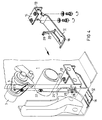
- FIG. 4 is a perspective view that serves to illustrate the attachment of a locking lever to a low-voltage circuit breaker.
- FIG. 1 a section of a control cabinet or similar switchgear is shown in simplified form, which contains a low-voltage circuit breaker 1 that is shown in part.
- a control panel 2 a control shaft 3 with a crank arm 4 and a lower cross member 5 are shown in particular.
- the circuit breaker 1 rests in the control cabinet on a base plate 6 in a manner not shown in detail.
- a door 7 is provided for closing the installation space of the circuit breaker 1.
- the door 7 has a cutout 10 for the passage of the control panel 2 of the circuit breaker 1.
- a locking device 11 which consists of several parts, which will be described below.
- a locking lever 12 which is attached to the cross member 5 in a vertically pivotable manner.
- a bearing bracket 13 is used for this purpose, which is attached with its one leg 14 to the middle leg 15 of the cross member 5 by means of a conventional screw connection.
- the other leg 16 of the bearing bracket 13 is longer than the parallel leg 17 of the Cross member 5, whereby the leg 17 acts with its lower edge as a bearing surface for the pivoting movement of the locking lever 12.
- the locking lever 12 rests on the front side of the other leg 20 of the cross member 5 in the idle state.
- a door-side end part 18 of the locking lever 12 has the shape of a bracket due to a design to be described, which bracket can overlap a locking lug 21 attached to the door 7, as shown in broken lines in FIG.
- the locking lever 12 is held by an opening spring 22 designed as a tension spring, the upper end of which is hooked into an opening 23 of the crank arm 4 located on the selector shaft 3.
- the opening spring 22 has an elongated end 24 with a hook-like end part 25 which is suspended in an opening 29 which is located in a widened end part 28 of an angled extension 26 of the locking lever 12.
- the cross member 5 is provided with a corresponding opening 27 which has a wider section for the passage of the end part 28 and a subsequent narrower section, as can be seen in particular from FIG.
- a closing spring 30 designed as a helical compression spring is arranged between the central part 15 of the cross member 5 and the locking lever 12.
- a support plate 31 is provided for the lower end of this spring.
- the opening spring 22 is designed to be stronger than the closing spring 30, such that the force of the closing spring 30 in the position of the parts shown in FIG. 1 is overcome by the opening spring 22 and the locking lever 12 is thereby held in the rest position shown.
- the switching shaft 30 closes the switching contacts of the circuit breaker 1 in a clockwise direction, the holding force acting on the locking lever 12 is reduced, so that the closing spring 30 now comes into effect and the locking lever 12 is dot-dashed shown closed position transferred.
- the bow-shaped front end part 18 of the locking lever 12 overlaps the locking lug 21 on the door 7.
- the locking lever 12 is a sheet metal part, which is shown in the extended state in FIG.
- recesses 32 are provided in a symmetrical arrangement at the end of the locking lever 12 provided for this purpose.
- the bearing lever 13 has an opening 33 in its leg 16 which has a narrower section 34 and a further section 35.
- the narrower section 34 corresponds to the width of the locking lever 12 in the region of the recesses 32, while the wider section 35 corresponds to the overall width of the locking lever 12.
- the locking lever 12 for attachment to the bearing bracket 13 can first be inserted into the wider part 35 of the opening 33 and then displaced in such a way that the recesses 32 reach the area of the material projections 36, which result from the transition between the wider section 35 to the narrower section 34 are formed.
- the position of the recess 33 in the leg 16 and the dimensioning of the leg 17 of the cross member 5 ensure that the locking lever remains in engagement with the projections 36 when the bearing bracket 13 in the position shown in FIG. 1 with the cross member 5 connected is.
- extension 26 is formed by a punch and a subsequent approximately right-angled bend.
- front bow-like end 18 of the locking lever 12 is formed by the punching process.
- FIG. 4 shows how the locking device can be attached to the circuit breaker 1.
- the locking lever 12 is inserted with its rear end into the opening of the bearing bracket 13 in the manner already described plugged in.
- This arrangement is mounted on the cross member 5 in such a way that the bearing bracket 13 rests on the middle part 15 of the cross member 5 and the extension 26 passes through the opening 27 in the middle part 15. Due to the slight displacement of the locking lever 12 during assembly, the widened end part 28 of the extension 26 passes over the narrower section of the opening 27, as a result of which the vertical pivoting path of the locking lever is restricted.
- the opening spring 22 can be hooked with its upper end into the opening 23 of the crank arm 4 and with its opposite hook-like end part 25 into the opening 29 at the end of the extension 26.
- the locking device is hereby functional, provided that a locking lug 21 has been attached to the door (not shown in FIG. 4) according to FIG. 1.
- the closing spring 30 is omitted, since the locking lever 12 already tries to assume the closed position according to the dash-dotted position in FIG. 1 due to gravity. This happens in particular when the opening spring 22 should break or a faulty or erroneously selected opening spring is used.
- the locking device can be overcome by an authorized operator by using an auxiliary tool.
- a small opening 8 is made in the door 7, which can also be closed in a known manner by a cover slide.
- a tool inserted through the opening 8 pushes against the obliquely angled end part 18 and lifts it, as a result of which the locking lug 21 is released. Subsequent closing of the door 7 is readily possible due to the inclined position of the end part 18.
Landscapes
- Patch Boards (AREA)
- Keying Circuit Devices (AREA)
- Relay Circuits (AREA)
- Coupling Device And Connection With Printed Circuit (AREA)
- Details Of Connecting Devices For Male And Female Coupling (AREA)
- Details Of Television Scanning (AREA)
- Emergency Protection Circuit Devices (AREA)
- Coin-Freed Apparatuses For Hiring Articles (AREA)
Abstract
Description
Die Erfindung betrifft einen Schaltschrank oder eine Schaltanlage mit einem Niederspannungs-Schaltgerät mit Schaltkontakten und einer Tür als Abschluß des Einbauraumes des Schaltgerätes sowie mit einer in Abhängigkeit von der Stellung der Schaltwelle des Schaltgerätes wirkenden Verriegelungseinrichtung, die eine an der Innenseite der Tür angebrachte Schließnase und einen mit der Schließnase zusammenwirkenden Riegelhebel umfaßt. Eine solche Verriegelungseinrichtung ist durch die DE-B-1 160 067 bekannt geworden. Für die Sicherheit des Bedienungspersonals einer solchen Schaltanlage ist es wesentlich, daß die Tür des Einbauraumes des Schaltgerätes nicht geöffnet werden kann, solange das Schaltgerät eingeschaltet ist. In diesem Fall besteht nämlich die Gefahr der Berührung spannungführender Teile. Darüberhinaus kann eine Gefährdung gegeben sein, wenn das Schaltgerät ein Leistungsschalter ist und dieser aufgrund eines für den Bedienenden nicht erkennbaren Vorganges ausgelöst wird und hierbei Schaltgase ausgestoßen werden. Durch die Erfindung soll eine einfach installierbare Einrichtung zum Verriegeln der Tür der Schaltanlage geschaffen werden, die eine zwangsläufige Zuhaltung der Tür gewährleistet, solange sich das Schaltgerät in der Einschaltstellung befindet und die bei einer mechanischen Störung selbsttätig in die Schließlage überführt wird oder in dieser verharrt.The invention relates to a control cabinet or a switchgear with a low-voltage switchgear with switch contacts and a door as a termination of the installation space of the switchgear and with a locking device acting as a function of the position of the switchgear shaft of the switchgear, which has a locking lug attached to the inside of the door and one includes locking lever cooperating with the locking lug. Such a locking device is known from DE-B-1 160 067. For the safety of the operating personnel of such a switchgear, it is essential that the door of the installation space of the switchgear cannot be opened as long as the switchgear is switched on. In this case there is a risk of touching live parts. In addition, there may be a hazard if the switching device is a circuit breaker and this is triggered due to a process that is not recognizable to the operator and switching gases are expelled in the process. The invention is intended to provide an easily installable device for locking the switchgear door, which ensures an inevitable locking of the door as long as the switchgear is in the switch-on position and which is automatically transferred to the closed position in the event of a mechanical fault or remains in it.
Gemäß der Erfindung ist hierzu der Riegelhebel an einem unteren Querträger des Schaltgerätes vertikal schwenkbar gelagert und durch eine Öffnungsfeder entgegen der Wirkungsrichtung der Schwerkraft beim Öffnen der Schaltkontakte des Schaltgerätes von der Schließstellung in eine Öffnungsstellung bewegbar. Die Öffnungsfeder bildet hierbei eine elastische Kupplung zwischen der Schaltwelle und dem Riegelhebel. Ein Versagen dieser Kupplung aus beliebigen Grund kann sich nur im sicheren Sinn, d. h. im Sinn der Verriegelung der Tür der Schaltanlage auswirken, weil dann der Riegelhebel aufgrund der Schwerkraft absinkt und die Schließnase der Tür erfaßt.According to the invention, for this purpose the locking lever is vertically pivotably mounted on a lower crossmember of the switching device and can be moved from the closed position into an open position by an opening spring against the direction of action of gravity when the switching contacts of the switching device are opened. The opening spring forms an elastic coupling between the selector shaft and the locking lever. Failure of this clutch for any reason can only occur in sure sense, ie affect in the sense of locking the door of the switchgear, because then the locking lever drops due to gravity and detects the locking lug of the door.
Zwischen dem Riegelhebel und dem Querträger des Schaltgerätes kann eine zusätzliche Schließfeder angeordnet sein, um den Riegelhebel noch sicherer in die Schließstellung zu überführen. Dabei ist die Öffnungsfeder zweckmäßig so zu bemessen, daß sie die Schließfeder beim Ausschalten des Schaltgerätes vollständig überwindet.An additional closing spring can be arranged between the locking lever and the crossmember of the switching device in order to move the locking lever even more securely into the closed position. The opening spring is expediently dimensioned so that it completely overcomes the closing spring when the switching device is switched off.
Die Anbringung des Riegelhebels an dem Schaltgerät, insbesondere die nachträgliche Anbringung, kann dadurch erleichtert sein, daß als Schwenklager für den Riegelhebel ein an dem Querträger lösbar anzubringender Lagerwinkel vorgesehen ist, der eine Einstecköffnung für das Ausnehmungen versehene Ende des Riegelhebels besitzt. Der Lagerwinkel und der Riegelhebel sind daher einfach zusammenzufügen, was vor dem Anbau der Teile an den Querträger des Schaltgerätes erfolgen kann.The attachment of the locking lever to the switching device, in particular the subsequent attachment, can be facilitated by the fact that a pivot bracket for the locking lever is a bearing bracket that can be detachably attached to the cross member and that has an insertion opening for the recessed end of the locking lever. The bearing bracket and the locking lever are therefore easy to put together, which can be done before the parts are attached to the cross member of the switchgear.
Die Einstecköffnung des Lagerwinkels kann T-förmig ausgebildet sein und kann einen breiteren, der Breite des Riegelhebels entsprechenden Abschnitt sowie einen schmaleren, der Breite des Riegelhebels im Bereich der Ausnehmungen entsprechend bemessenen Abschnitt aufweisen, wobei der Riegelhebel durch einen Schenkel des Querträgers des Schaltgerätes im Bereich des schmaleren Abschnittes der Öffnung des Tragwinkels gehalten wird. Die beiden Teile sind daher auf einfache Weise zusammenzufügen und wieder zu trennen, solange sie noch nicht an dem Querträger angebracht sind. Durch die angegebene Bemessung wird erreicht, daß die Lagerflächen für den Riegelhebel auf dessen einer Seite durch eine Kante der Einstecköffnung des Tragwinkels und die gegenüberliegende Lagerfläche durch die Kante des Schenkels des Querträgers gebildet wird.The insertion opening of the bearing bracket can be T-shaped and can have a wider section corresponding to the width of the locking lever and a narrower section corresponding to the width of the locking lever in the area of the recesses, the locking lever being in the area by a leg of the crossbeam of the switching device of the narrower section of the opening of the support bracket is held. The two parts are therefore easy to assemble and separate as long as they are not yet attached to the cross member. The specified dimensioning ensures that the bearing surfaces for the locking lever is formed on one side by an edge of the insertion opening of the support bracket and the opposite bearing surface by the edge of the leg of the cross member.
Es empfiehlt sich, den Riegelhebel als Blechteil zu gestalten. Ferner kann der Riegelhebel einen durch Freistanzen und Herausbiegen gebildeten Fortsatz aufweisen, der als Widerlager für die Öffnungsfeder dient. Durch die erwähnte Freistanzung kann zugleich ein bügelartiges Endteil zum Übergreifen der Schließnase gebildet sein. Ferner kann durch eine Abschrägung des bügelartigen Endteiles für einen zuverlässigen Eingriff mit der Schließnase und für eine einfache Handhabung bei einer befugten Überwindung der Verriegelungseinrichtung gesorgt sein.It is advisable to design the locking lever as a sheet metal part. Furthermore, the locking lever can have an extension formed by punching out and bending out, which serves as an abutment for the opening spring. Due to the above-mentioned punching, a bow-like end part can also be formed for gripping over the locking nose. Furthermore, bevelling of the bow-like end part can ensure reliable engagement with the locking lug and simple handling when the locking device is authorized to be overcome.
Der Fortsatz des Riegelhebels kann einen verbreiterten Endteil besitzen, während in dem Querträger eine abgestufte Öffnung mit einem breiteren, dem Endteil angepaßten Abschnitt und einem anschließenden schmaleren Abschnitt angebracht ist. Dies ermöglicht es, den Fortsatz in ähnlicher Weise durch die Öffnung des Querträgers einzuführen, wie dies für die Anbringung des Riegelhebels an dem Lagerwinkel beschrieben wurde. Der verbreiterte Endteil des Fortsatzes wirkt dabei als Anschlag an dem Querträger, da der Endteil durch den schmaleren Abschnitt der Öffnung in dem Querträger nicht hindurchtreten kann.The extension of the locking lever can have a widened end part, while in the cross member a stepped opening with a wider section adapted to the end part and a subsequent narrower section is provided. This makes it possible to insert the extension through the opening of the cross member in a manner similar to that described for the attachment of the locking lever to the bearing bracket. The widened end part of the extension acts as a stop on the cross member, since the end part cannot pass through the narrower section of the opening in the cross member.
Die Öffnungsfeder für den Riegelhebel kann vorzugsweise eine Zugfeder sein, die mit ihrem einen Ende an einem Kurbelarm der Schaltwelle angreift und deren anderes Ende einen gestreckten Abschnitt mit einem hakenartigen Endteil besitzt, der in eine Öffnung am Ende des Fortsatzes des Riegelhebels eingehängt ist. Durch die Verwendung einer Zugfeder mit einem gestreckten Endabschnitt wird erreicht, daß die Zugfeder als einziges Teil zur Verbindung der Schaltwelle mit dem Riegelhebel benötigt wird anstelle einer gleichfalls in Betracht kommenden, jedoch aufwendigeren Kombination einer Feder mit einer Zugstange oder einem ähnlichen Teil.The opening spring for the locking lever can preferably be a tension spring which engages with one end on a crank arm of the selector shaft and the other end of which has an elongated section with a hook-like end part which is suspended in an opening at the end of the extension of the locking lever. By using a tension spring with an elongated end section it is achieved that the tension spring is required as the only part for connecting the selector shaft to the locking lever instead of an equally possible, but more complex combination of a spring with a tension rod or a similar part.
Die Erfindung wird im folgenden anhand des in den Figuren dargestellten Ausführungsbeispieles näher erläutert.The invention is explained below with reference to the embodiment shown in the figures.
Die Figur 1 zeigt im Schnitt die im Zusammenhang mit der Erfindung wesentlichen Teile eines Niederspannungs-Leistungsschalters und einer Schaltanlage.FIG. 1 shows in section the essential parts of a low-voltage circuit breaker and a switchgear in connection with the invention.
Ein Riegelhebel ist in der Figur 2 als teilweise fertiggestelltes Blechteil gezeigt.A locking lever is shown in Figure 2 as a partially finished sheet metal part.
In der Figur 3 ist ein für den Riegelhebel vorgesehener Lagerwinkel dargestellt.FIG. 3 shows a bearing bracket provided for the locking lever.
Die Figur 4 ist eine perspektivische Darstellung, die zur Veranschaulichung der Anbringung eines Riegelhebels an einem Niederspannungs-Leistungsschalter dient.FIG. 4 is a perspective view that serves to illustrate the attachment of a locking lever to a low-voltage circuit breaker.
In der Figur 1 ist vereinfacht ein Ausschnitt aus einem Schaltschrank oder einer ähnlichen Schaltanlage dargestellt, die einen teilweise gezeigten Niederspannungs-Leistungsschalter 1 enthält. Von diesem sind insbesondere ein Bedienungspult 2, eine Schaltwelle 3 mit einem Kurbelarm 4 sowie ein unterer Querträger 5 gezeigt. Der Leistungsschalter 1 ruht in dem Schaltschrank in nicht näher dargestellter Weise auf einer Bodenplatte 6. Eine Tür 7 ist zum Verschließen des Einbauraumes des Leistungsschalters 1 vorgesehen. Die Tür 7 besitzt einen Ausschnitt 10 zum Durchtritt des Bedienungspultes 2 des Leistungsschalters 1.In FIG. 1, a section of a control cabinet or similar switchgear is shown in simplified form, which contains a low-
Um sicher zu stellen, daß die Tür 7 nicht geöffnet werden kann, wenn der Leistungsschalter 1 eingeschaltet ist, ist eine Verriegelungseinrichtung 11 vorgesehen, die aus mehreren, im folgenden noch zu beschreibenden Teilen besteht. Von Bedeutung ist insbesondere ein Riegelhebel 12, der vertikal schwenkbar an dem Querträger 5 angebracht ist. Hierzu dient ein Lagerwinkel 13, der mit seinem einen Schenkel 14 mittels einer üblichen Schraubverbindung an dem mittleren Schenkel 15 des Querträgers 5 befestigt ist. Der andere Schenkel 16 des Lagerwinkels 13 ist länger als der parallel verlaufende Schenkel 17 des Querträgers 5, wodurch der Schenkel 17 mit seiner Unterkante als Lagerfläche für die Schwenkbewegung des Riegelhebels 12 wirkt. Nahe seinem vorderen Ende liegt der Riegelhebel 12 im Ruhezustand an der Stirnseite des anderen Schenkels 20 des Querträgers 5 an. Ein türseitiger Endteil 18 des Riegelhebels 12 hat aufgrund einer noch zu beschreibenden Gestaltung die Form eines Bügels, der eine an der Tür 7 angebrachte Schließnase 21 zu übergreifen vermag, wie in der Figur 1 strichpunktiert gezeigt ist.In order to ensure that the door 7 cannot be opened when the
In der ausgezogen gezeigten Ruhestellung wird der Riegelhebel 12 durch eine als Schraubenzugfeder ausgebildete Öffnungsfeder 22 gehalten, deren oberes Ende in eine Öffnung 23 des auf der Schaltwelle 3 befindlichen Kurbelarmes 4 eingehängt ist. An ihrem der Öffnung 23 gegenüberliegenden Ende besitzt die Öffnungsfeder 22 ein gestrecktes Ende 24 mit einem hakenartigen Endteil 25, das in eine Öffnung 29 eingehängt ist, die sich in einem verbreiterten Endteil 28 eines abgewinkelten Fortsatzes 26 des Riegelhebels 12 befindet. Für den Durchtritt des Fortsatzes 26 ist der Querträger 5 mit einer entsprechenden Öffnung 27 versehen, die einen breiteren Abschnitt für den Durchtritt des Endteiles 28 und einen anschließenden schmaleren Abschnitt aufweist, wie insbesondere der Figur 4 zu entnehmen ist. Ferner ist zwischen dem Mittelteil 15 des Querträgers 5 und dem Riegelhebel 12 eine als Schraubendruckfeder ausgebildete Schließfeder 30 angeordnet. Für das untere Ende dieser Feder ist ein Auflageteller 31 vorgesehen. Die Öffnungsfeder 22 ist stärker als die Schließfeder 30 ausgebilet, derart, daß die Kraft der Schließfeder 30 in der in der Figur 1 gezeigten Stellung der Teile durch die Öffnungsfeder 22 überwunden und dadurch der Riegelhebel 12 in der dargestellten Ruhelage gehalten wird. Sobald die Schaltwelle 30 zum Schließen der Schaltkontakte des Leistungsschalters 1 eine Schwenkbewegung im Uhrzeigersinn ausführt, verringert sich die auf den Riegelhebel 12 wirkende Haltekraft, so daß nun die Schließfeder 30 zur Wirkung gelangt und den Riegelhebel 12 in die strichpunktiert gezeigte Schließstellung überführt. In dieser übergreift das bügelförmige vordere Endteil 18 des Riegelhebels 12 die Schließnase 21 an der Tür 7.In the rest position shown in the extended position, the
Der Riegelhebel 12 ist ein Blechteil, das in der Figur 2 im gestreckten Zustand gezeigt ist. Zur Lagerung an dem Lagerwinkel 13 sind an dem hierzu vorgesehenen Ende des Riegelhebels 12 in symmetrischer Anordnung Ausnehmungen 32 vorgesehen. Der Lagerhebel 13 besitzt gemäß der Figur 3 in seinem Schenkel 16 eine Öffnung 33, die einen schmaleren Abschnitt 34 und einen weiteren Abschnitt 35 aufweist. Der schmalere Abschnitt 34 entspricht dabei der Breite des Riegelhebels 12 im Bereich der Ausnehmungen 32, während der breitere Abschnitt 35 der Gesamtbreite des Riegelhebels 12 entspricht. Auf diese Weise kann der Riegelhebel 12 zur Anbringung an dem Lagerwinkel 13 zunächst in den breiteren Teil 35 der Öffnung 33 eingesteckt und dann derart verschoben werden, daß die Ausnehmungen 32 in den Bereich der Materialvorsprünge 36 gelangen, die durch den Übergang zwischen dem breiteren Abschnitt 35 zu dem schmaleren Abschnitt 34 gebildet sind. Durch die Lage der Ausnehmung 33 in dem Schenkel 16 und die Bemessung des Schenkels 17 des Querträgers 5 ist dafür gesorgt, daß der Riegelhebel in Eingriff mit den Vorsprüngen 36 bleibt, wenn der Lagerwinkel 13 in der in der Figur 1 gezeigten Stellung mit dem Querträger 5 verbunden ist.The
Aus der Figur 2 ist ferner zu entnehmen, daß der Fortsatz 26 durch eine Freistanzung und eine nachfolgende etwa rechtwinklige Biegung gebildet ist. Zugleich wird durch den Stanzvorgang das vordere bügelartige Ende 18 des Riegelhebels 12 gebildet.From Figure 2 it can also be seen that the
In der Figur 4 ist gezeigt, wie sich die Verriegelungseinrichtung an dem Leistungsschalter 1 anbringen läßt. Zunächst wird der Riegelhebel 12 in der bereits beschriebenen Weise mit seinem hinteren Ende in die Öffnung des Lagerwinkels 13 eingesteckt. Diese Anordnung wird an dem Querträger 5 in der Weise montiert, daß der Lagerwinkel 13 auf dem Mittelteil 15 des Querträgers 5 aufliegt und der Fortsatz 26 durch die Öffnung 27 in dem Mittelteil 15 durchtritt. Durch die geringe Verschiebung des Riegelhebels 12 bei der Montage gelangt dabei der verbreiterte Endteil 28 des Fortsatzes 26 über den schmaleren Abschnitt der Öffnung 27, wodurch der vertikale Schwenkweg des Riegelhebels beschränkt ist. Nun kann die Öffnungsfeder 22 mit ihrem oberen Ende in die Öffnung 23 des Kurbelarmes 4 und mit ihrem gegenüberliegenden hakenartigen Endteil 25 in die Öffnung 29 am Ende des Fortsatzes 26 eingehängt werden. Hiermit ist die Verriegelungseinrichtung funktionsfähig, sofern an der in der Figur 4 nicht sichtbaren Tür entsprechend der Figur 1 eine Schließnase 21 angebracht wurde. Bei dem Ausführungsbeispiel gemäß der Figur 4 ist die Schließfeder 30 fortgelassen, da der Riegelhebel 12 bereits aufgrund der Schwerkraft bestrebt ist, die Schließstellung gemäß der strichpunktierten Stellung in Figur 1 einzunehmen. Dies geschieht insbesondere auch dann, wenn die Öffnungsfeder 22 brechen sollte oder eine fehlerhafte oder irrtümlich gewählte Öffnungsfeder eingesetzt wird.FIG. 4 shows how the locking device can be attached to the
Wie dies an sich bekannt ist, kann die Verriegelungseinrichtung durch eine hierzu befugte Bedienungsperson überwunden werden, indem ein Hilfswerkzeug benutzt wird. Hierzu ist in der Tür 7 eine kleine Öffnung 8 angebracht, die noch, in ebenfalls bekannter Weise, durch einen Abdeckschieber verschließbar sein kann. Wie man erkennt, stößt ein durch die Öffnung 8 eingeführtes Werkzeug gegen das schräg abgewinkelte Endteil 18 und hebt dieses an, wodurch die Schließnase 21 freigegeben wird. Ein nachfolgendes Schließen der Tür 7 ist aufgrund der Schrägstellung des Endteiles 18 ohne weiteres möglich.As is known per se, the locking device can be overcome by an authorized operator by using an auxiliary tool. For this purpose, a
Claims (8)
- Switching cabinet or switching installation with a low-voltage switching device (1) with switching contacts and a door (7) to close off the accommodation for the switching device (1) and with an interlock device (11) acting as a function of the position of the switching operating shaft (3) of the switching device (1), and comprising a catch (21) mounted on the inside of the door (7) and a locking lever (12) acting in conjunction with the catch (21), characterized in that the locking lever (12) is mounted vertically hinged near to a lower cross bearer (5) of the switching device (1) and in that an opening spring (22) may be moved into an opening position from the closed position against the direction of action of gravity when the switching contacts of the switching device (1) are opened.
- Switching cabinet in accordance with claim 1, characterized in that an additional closing spring (30) is mounted between the locking lever (12) and the cross bearer (5) of the switching device (1).
- Switching cabinet in accordance with claim 2, characterized in that a bearing bracket (13) which can be removably mounted on the cross bearer (5) having an insertion aperture (33) for the end of the locking lever (12) provided with recesses (32) is provided as the pivot bearing for the locking lever (12).
- Switching cabinet in accordance with claim 3, characterized in that the insertion aperture (33) of the bearing bracket (13) is formed in the shape of a T and has a broader section (35) corresponding to the width of the locking lever (12) and a narrower section (34) dimensioned in accordance with the width of the locking lever (12) in the region of the recesses (32), with the locking lever (12) being retained by an arm (17) of the cross bearer (5) of the switching device (1) in the region of the narrower cut-out (34) of the aperture (33) in the bearing bracket (13).
- Switching cabinet in accordance with one of the preceding claims, characterized in that the locking lever (12) consists of metal plate and has an extension (26) formed by free stamping and bending, serving as the abutment for the opening spring (22).
- Switching cabinet in accordance with claim 5, characterized in that the extension (26) of the locking lever (12) has a broadened end piece (28) and in that a graduated aperture (27) with widened section matching the end piece (28) of the extension (26) and an adjacent narrower section is provided in the cross bearer (5).
- Switching cabinet in accordance with one of the preceding claims, characterized in that the locking lever (12) has a chamfered forward bow-shaped end piece (18) to engage with the catch (21).
- Switching cabinet in accordance with one of the preceding claims, characterized in that the opening spring (22) is a tension spring, one end of which engages with a crank arm (4) on the operating shaft (3) and the other end of which has an extended section (24) with a hook-shaped end piece (25) which is hooked into an aperture (28) at the end of the extension (26) on the locking lever (12).
Applications Claiming Priority (2)
| Application Number | Priority Date | Filing Date | Title |
|---|---|---|---|
| DE8805458U DE8805458U1 (en) | 1988-04-20 | 1988-04-20 | Control cabinet with a low-voltage circuit breaker |
| DE8805458U | 1988-04-20 |
Publications (3)
| Publication Number | Publication Date |
|---|---|
| EP0338969A2 EP0338969A2 (en) | 1989-10-25 |
| EP0338969A3 EP0338969A3 (en) | 1991-04-03 |
| EP0338969B1 true EP0338969B1 (en) | 1994-10-26 |
Family
ID=6823343
Family Applications (1)
| Application Number | Title | Priority Date | Filing Date |
|---|---|---|---|
| EP89730100A Expired - Lifetime EP0338969B1 (en) | 1988-04-20 | 1989-04-11 | Switch gear cubicle with a low tension switch apparatus |
Country Status (4)
| Country | Link |
|---|---|
| EP (1) | EP0338969B1 (en) |
| AT (1) | ATE113406T1 (en) |
| DE (2) | DE8805458U1 (en) |
| NO (1) | NO174649C (en) |
Families Citing this family (1)
| Publication number | Priority date | Publication date | Assignee | Title |
|---|---|---|---|---|
| DE102010025240A1 (en) * | 2010-06-26 | 2011-12-29 | Eaton Industries Gmbh | Locking device for a cabinet door |
Family Cites Families (4)
| Publication number | Priority date | Publication date | Assignee | Title |
|---|---|---|---|---|
| DE1037549B (en) * | 1952-09-25 | 1958-08-28 | Siemens Ag | Disconnectable power socket with mutual locking between switch and socket |
| US3028459A (en) * | 1959-02-19 | 1962-04-03 | Fed Pacific Electric Co | Switch and enclosure therefor |
| US3194907A (en) * | 1963-06-28 | 1965-07-13 | Gen Electric | Interlock mechanism for an enclosed electric switch |
| US3534186A (en) * | 1969-08-06 | 1970-10-13 | Giddings & Lewis | Door interlock system for electrical control cabinets |
-
1988
- 1988-04-20 DE DE8805458U patent/DE8805458U1/en not_active Expired
-
1989
- 1989-04-11 DE DE58908548T patent/DE58908548D1/en not_active Expired - Fee Related
- 1989-04-11 AT AT89730100T patent/ATE113406T1/en not_active IP Right Cessation
- 1989-04-11 EP EP89730100A patent/EP0338969B1/en not_active Expired - Lifetime
- 1989-04-20 NO NO891637A patent/NO174649C/en unknown
Also Published As
| Publication number | Publication date |
|---|---|
| NO174649B (en) | 1994-02-28 |
| EP0338969A3 (en) | 1991-04-03 |
| EP0338969A2 (en) | 1989-10-25 |
| NO891637D0 (en) | 1989-04-20 |
| NO891637L (en) | 1989-10-23 |
| DE8805458U1 (en) | 1989-08-17 |
| DE58908548D1 (en) | 1994-12-01 |
| NO174649C (en) | 1994-06-08 |
| ATE113406T1 (en) | 1994-11-15 |
Similar Documents
| Publication | Publication Date | Title |
|---|---|---|
| DE3336207C3 (en) | Electrical switch with control lever stop when contacts are welded together | |
| DE3885989T2 (en) | Encapsulated switchboard. | |
| EP2140521B1 (en) | Installation switchgear having a spring-loaded terminal arrangement | |
| EP0226532B1 (en) | Electrical switching cubicle with a racking drive for a movable switching apparatus | |
| DE2823422A1 (en) | DEVICE FOR ENGAGING AND RELEASING PRINTED CIRCUIT CARDS | |
| DE29913698U1 (en) | Multi-pole switch fuse arrangement for busbar systems | |
| DE2600333B2 (en) | Resettable circuit breaker | |
| EP0235492B1 (en) | Slide-in frame with a shutter plate for a disconnecting arrangement | |
| DE20214209U1 (en) | Double circuit switch design with overload protection | |
| DE4420580C1 (en) | Switchgear with a device dependent on the switching position for retracting and extending relative to a slide-in frame | |
| EP0892420B1 (en) | Locking mechanism for an electrical excesscurrent switch for motor protection | |
| DE10250214B3 (en) | Device for fixing a circuit breaker in a slide-in frame | |
| EP0338969B1 (en) | Switch gear cubicle with a low tension switch apparatus | |
| DE2705330C2 (en) | Electrical switch, in particular motor protection switch | |
| EP3045644A1 (en) | Device for preventing the locking of a door | |
| DE3880653T2 (en) | Switches, in particular for use as automatic switches. | |
| EP0143927B1 (en) | Device for returning the contact carrier of an electromagnetic switching device, especially of a protective circuit breaker | |
| DE69301278T2 (en) | Locking device for load switches with hinged lid | |
| DE2551858C2 (en) | Limit switch | |
| DE10061783C1 (en) | Interlocking device for electrical switching devices incorporates safety function preventing incorrect operation upon contact welding | |
| AT1162U1 (en) | POWER SWITCHGEAR WITH A HOUSING AND WITH A LID | |
| DE1588944C3 (en) | BRACKET FOR A REPLACEABLE FUSE | |
| DE29800957U1 (en) | Switchgear with safety function | |
| DE29614028U1 (en) | Snap switch with housing | |
| DE3425996C2 (en) |
Legal Events
| Date | Code | Title | Description |
|---|---|---|---|
| PUAI | Public reference made under article 153(3) epc to a published international application that has entered the european phase |
Free format text: ORIGINAL CODE: 0009012 |
|
| AK | Designated contracting states |
Kind code of ref document: A2 Designated state(s): AT BE CH DE FR GB IT LI NL SE |
|
| PUAL | Search report despatched |
Free format text: ORIGINAL CODE: 0009013 |
|
| 17P | Request for examination filed |
Effective date: 19901220 |
|
| AK | Designated contracting states |
Kind code of ref document: A3 Designated state(s): AT BE CH DE FR GB IT LI NL SE |
|
| 17Q | First examination report despatched |
Effective date: 19940202 |
|
| GRAA | (expected) grant |
Free format text: ORIGINAL CODE: 0009210 |
|
| AK | Designated contracting states |
Kind code of ref document: B1 Designated state(s): AT BE CH DE FR GB IT LI NL SE |
|
| REF | Corresponds to: |
Ref document number: 113406 Country of ref document: AT Date of ref document: 19941115 Kind code of ref document: T |
|
| REF | Corresponds to: |
Ref document number: 58908548 Country of ref document: DE Date of ref document: 19941201 |
|
| ITF | It: translation for a ep patent filed | ||
| GBT | Gb: translation of ep patent filed (gb section 77(6)(a)/1977) |
Effective date: 19941222 |
|
| ET | Fr: translation filed | ||
| PGFP | Annual fee paid to national office [announced via postgrant information from national office to epo] |
Ref country code: GB Payment date: 19950320 Year of fee payment: 7 |
|
| PGFP | Annual fee paid to national office [announced via postgrant information from national office to epo] |
Ref country code: NL Payment date: 19950817 Year of fee payment: 7 Ref country code: BE Payment date: 19950817 Year of fee payment: 7 |
|
| PLBE | No opposition filed within time limit |
Free format text: ORIGINAL CODE: 0009261 |
|
| STAA | Information on the status of an ep patent application or granted ep patent |
Free format text: STATUS: NO OPPOSITION FILED WITHIN TIME LIMIT |
|
| 26N | No opposition filed | ||
| PGFP | Annual fee paid to national office [announced via postgrant information from national office to epo] |
Ref country code: SE Payment date: 19960410 Year of fee payment: 8 |
|
| PG25 | Lapsed in a contracting state [announced via postgrant information from national office to epo] |
Ref country code: GB Effective date: 19960411 |
|
| PG25 | Lapsed in a contracting state [announced via postgrant information from national office to epo] |
Ref country code: BE Effective date: 19960430 |
|
| BERE | Be: lapsed |
Owner name: SIEMENS A.G. Effective date: 19960430 |
|
| PG25 | Lapsed in a contracting state [announced via postgrant information from national office to epo] |
Ref country code: NL Effective date: 19961101 |
|
| GBPC | Gb: european patent ceased through non-payment of renewal fee |
Effective date: 19960411 |
|
| NLV4 | Nl: lapsed or anulled due to non-payment of the annual fee |
Effective date: 19961101 |
|
| PGFP | Annual fee paid to national office [announced via postgrant information from national office to epo] |
Ref country code: AT Payment date: 19970326 Year of fee payment: 9 |
|
| PG25 | Lapsed in a contracting state [announced via postgrant information from national office to epo] |
Ref country code: SE Effective date: 19970412 |
|
| PGFP | Annual fee paid to national office [announced via postgrant information from national office to epo] |
Ref country code: CH Payment date: 19970715 Year of fee payment: 9 |
|
| EUG | Se: european patent has lapsed |
Ref document number: 89730100.8 |
|
| PG25 | Lapsed in a contracting state [announced via postgrant information from national office to epo] |
Ref country code: AT Free format text: LAPSE BECAUSE OF NON-PAYMENT OF DUE FEES Effective date: 19980411 |
|
| PG25 | Lapsed in a contracting state [announced via postgrant information from national office to epo] |
Ref country code: LI Free format text: LAPSE BECAUSE OF NON-PAYMENT OF DUE FEES Effective date: 19980430 Ref country code: CH Free format text: LAPSE BECAUSE OF NON-PAYMENT OF DUE FEES Effective date: 19980430 |
|
| REG | Reference to a national code |
Ref country code: CH Ref legal event code: PL |
|
| PGFP | Annual fee paid to national office [announced via postgrant information from national office to epo] |
Ref country code: FR Payment date: 20010420 Year of fee payment: 13 |
|
| PGFP | Annual fee paid to national office [announced via postgrant information from national office to epo] |
Ref country code: DE Payment date: 20010620 Year of fee payment: 13 |
|
| PG25 | Lapsed in a contracting state [announced via postgrant information from national office to epo] |
Ref country code: DE Free format text: LAPSE BECAUSE OF NON-PAYMENT OF DUE FEES Effective date: 20021101 |
|
| PG25 | Lapsed in a contracting state [announced via postgrant information from national office to epo] |
Ref country code: FR Free format text: LAPSE BECAUSE OF NON-PAYMENT OF DUE FEES Effective date: 20021231 |
|
| REG | Reference to a national code |
Ref country code: FR Ref legal event code: ST |
|
| PG25 | Lapsed in a contracting state [announced via postgrant information from national office to epo] |
Ref country code: IT Free format text: LAPSE BECAUSE OF NON-PAYMENT OF DUE FEES Effective date: 20050411 |