EP0338957A1 - Computergesteuerte Schnittstelle für 8 mm-Format-Kamerarekorder/Videorekorder und Zusatzgeräte - Google Patents
Computergesteuerte Schnittstelle für 8 mm-Format-Kamerarekorder/Videorekorder und Zusatzgeräte Download PDFInfo
- Publication number
- EP0338957A1 EP0338957A1 EP89440032A EP89440032A EP0338957A1 EP 0338957 A1 EP0338957 A1 EP 0338957A1 EP 89440032 A EP89440032 A EP 89440032A EP 89440032 A EP89440032 A EP 89440032A EP 0338957 A1 EP0338957 A1 EP 0338957A1
- Authority
- EP
- European Patent Office
- Prior art keywords
- video
- interface
- serial
- parallel
- computer
- Prior art date
- Legal status (The legal status is an assumption and is not a legal conclusion. Google has not performed a legal analysis and makes no representation as to the accuracy of the status listed.)
- Granted
Links
Images

Classifications
-
- H—ELECTRICITY
- H04—ELECTRIC COMMUNICATION TECHNIQUE
- H04N—PICTORIAL COMMUNICATION, e.g. TELEVISION
- H04N5/00—Details of television systems
- H04N5/222—Studio circuitry; Studio devices; Studio equipment
-
- H—ELECTRICITY
- H04—ELECTRIC COMMUNICATION TECHNIQUE
- H04N—PICTORIAL COMMUNICATION, e.g. TELEVISION
- H04N23/00—Cameras or camera modules comprising electronic image sensors; Control thereof
- H04N23/60—Control of cameras or camera modules
- H04N23/66—Remote control of cameras or camera parts, e.g. by remote control devices
-
- Y—GENERAL TAGGING OF NEW TECHNOLOGICAL DEVELOPMENTS; GENERAL TAGGING OF CROSS-SECTIONAL TECHNOLOGIES SPANNING OVER SEVERAL SECTIONS OF THE IPC; TECHNICAL SUBJECTS COVERED BY FORMER USPC CROSS-REFERENCE ART COLLECTIONS [XRACs] AND DIGESTS
- Y10—TECHNICAL SUBJECTS COVERED BY FORMER USPC
- Y10S—TECHNICAL SUBJECTS COVERED BY FORMER USPC CROSS-REFERENCE ART COLLECTIONS [XRACs] AND DIGESTS
- Y10S358/00—Facsimile and static presentation processing
- Y10S358/906—Hand-held camera with recorder in a single unit
Definitions
- the present invention relates to an interface (FIG. 1), an apparatus which allows the simultaneous control by computer of one or more camcorders (cameras and video recorders) and 8 mm video recorders with counter and remote control socket, and of various remote control accessories such as a switch.
- This invention relates to the fields of electronics, computers and video.
- this interface does not require any electronic or electrical intervention inside the devices used, except those possibly provided by the manufacturer.
- the access time to the images on the video cassette is of the order of a few seconds, which certainly makes it one of the systems, or even the fastest interactive computer-video system after the video disc.
- This interface consists of a set of electronic cards which can be internal or external to a computer, and which allow, thanks to the appropriate software, to simultaneously control the 8mm camcorders and video recorders and the accessories described above.
- 8mm camcorders and VCRs must have a meter and be equipped with a plug or remote control.
- the computer it must be provided either with a card fitted with an RS232 type serial signal output socket, or with a parallel input / output interface card (minimum 16 lines), preferably TTL level.
- the first function of this interface is to be able to simultaneously remote control all the functions of one or more camcorders (cameras and video recorders) or 8mm video recorders, and all the accessories described above from a computer, either in direct mode, either in programmed mode.
- the second function of this interface is to be able to select by computer video and sound images, contained on one or more cassettes of camcorders or video recorders 8m to allow the user to: - view or transfer the selected images, from one or more 8mm videocassettes, and associate them with images, text, graphics, or computer generated images obtained by the computer or another source.
- These images can each be viewed on their own screen or on a common screen thanks to: - or a video switch integrated as an accessory to the invention, ensuring the selection of the image and the sound to view or use, - either by using an image overlay interface, not part of the patent described here, - put in the computer memory the selection of one or more video sequences coming from one or more 8mm video cassettes, to call them in any order at any time to then view them, integrate them to an application or copy them from one VCR to another.
- the object of the invention is to adapt the parallel or serial electronic signals coming from a computer, to the particular protocol of the remote control signals of the devices to be controlled described above.
- the bi-directional serial signal which allows to control the 8mm camcorder / video recorder (s) interactively, is made up of a set of 8 words minimum, each comprising 1 start bit and 8 data bits of about 100 ⁇ s. Each word has a duration between 1100 and 1800 ⁇ s.
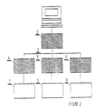
- the interface consists of several sub-assemblies which can be ordered according to Figure 2: - a serial / parallel-parallel / serial converter card (2), characterized in that it comprises, on the one hand, a serial-parallel converter which transforms the signals of the serial output of RS232 type, of any computer provided with this socket, in parallel signals of 8 lines or more, usable by the interface to remote control 8mm camcorders and video recorders and accessories, and on the other hand a parallel / serial converter converting parallel information (8 or more), coming from the interface and which contain the counter information of the camcorders and 8 mm video recorders, in serial RS232 type signals going to the computer.
- a serial / parallel-parallel / serial converter card (2) characterized in that it comprises, on the one hand, a serial-parallel converter which transforms the signals of the serial output of RS232 type, of any computer provided with this socket, in parallel signals of 8 lines or more, usable by the interface to remote control 8mm camcorders and video record
- All of the parallel information is grouped together on a control bus 3 of the interface which therefore comprises at least 16 lines in parallel.
- Said card is designed around a universal asynchronous transmitter / receiver circuit (UART AY3 1015 or equivalent circuit) and its control logic.
- a clock consisting of a quartz oscillator and a frequency divider selectable cadence the asynchronous transmitter / receiver.
- the transmission speed (number of bauds), the number of data bits, stops and parities are selectable by a switching device.
- Buffers with 3-state logic are used to connect the parallel inputs and outputs to the interface control bus. This makes it possible to electrically disconnect the card 2, if one wishes to connect directly to the control bus parallel inputs / outputs coming from a computer card.
- a resistance-capacitor circuit ensures zeroing, when the assembly is powered up.
- a voltage adapter device makes it possible to transform the RS232 levels into TTL levels and vice versa, - a control bus 3, characterized in that it comprises at least 16 parallel input / output control wires, - a motherboard 4, composed of the following subsets: - a stabilized power supply, characterized by its function of transforming the mains voltage into stabilized DC voltages, necessary for the operation of all the circuits making up the device.
- the DC voltage supply could also be taken from a source external to the interface, - an 8 mm camcorder / VCR selector to be controlled, characterized by a device which, from information sent on the command bus, selects, using analog switches (type CD 4066 or similar), the serial signal from the 8 mm camcorder or video recorder to be remote controlled 7, - a clock, characterized by an oscillator delivering a square signal with adjustable frequency, or controlled by quartz, which may include a frequency divider, for better time stability of the signal produced.
- a source external to the interface - an 8 mm camcorder / VCR selector to be controlled, characterized by a device which, from information sent on the command bus, selects, using analog switches (type CD 4066 or similar), the serial signal from the 8 mm camcorder or video recorder to be remote controlled 7, - a clock, characterized by an oscillator delivering a square signal with adjustable frequency, or controlled by quartz, which may include a frequency divider, for better time stability of the signal
- This clock is synchronized by the start bits of the serial signal of 8 mm camcorders and video recorders, it clock the different circuits of the motherboard 4, - a parallel / serial converter characterized by a device which makes it possible to transform the parallel signals of the control bus into serial signals of remote control of the video recorders / camcorders 8 mm.
- 8-bit serial coding which is part of the first 2 words of this signal, allows remote control of all the functions (playback, rewind, stop, pause, ...) of 8mm camcorders / video recorders.
- this circuit could include a serial / parallel converter, characterized by its decoding function in the serial signal of words 2, 3 and 4, indicating the operating state of the 8 mm camcorders / video recorders controlled, into a parallel signal sent on the command bus, - a serial / parallel converter, characterized by its function of decoding words 6, 7 and 8 from the serial signal of 8 mm camcorders / video recorders into a parallel signal containing the counter signals.
- words 7 and 8 include the multi-plexed information of the counter and word 6 the algorithm for coding the information of words 7 and 8.
- the information of words 7 and 8, or information of the counter, are stored successively in memories, according to the algorithm delivered by the information of word 6, these memories each having their own address may be read alternately by the interface control bus. All of these circuits are made with conventional logic doors and circuits, but could be replaced by a microprocessor system ensuring the same function (8052 AH, ...), - interfaces of the remote-controlled outputs 6, characterized in that they make it possible to transform the control signals, coming from the control bus, into activating signals, either open collector transistors, or electromechanical or electronic relays, or equivalent systems , such as : opto-couplers ...
- These interfaces allow remote control of accessories or other devices 9, which 1 could be connected to 1 interface, - a video switch 5, used to select the signals from one of the video and sound sources 8 to be viewed on a television or monitor.
- This switch is characterized by the use of analog switches (type CD 4066 or similar), operating their switching on the signals normally present on a SCART socket (red, green, blue, slow switching, sound, ). The switching is remotely controlled from the information sent on the control bus by the computer.
- All of the electronic circuits are produced on one or more printed circuits. They can be housed in one or more boxes, or remain in the state in order to be introduced into a particular device (computer, video recorder, ).
- This interface with the appropriate software allows 1 user: - to select in advance, on one or more 8 mm video cassettes, sequences of images and sounds to present them during lectures or conferences, - video and sound editing of filmed documents, - integrate your own images and sounds into computer software (questions asked by the computer and depending on the answer, presentation of the corresponding images, or questions by 1 image from the video recorder and analysis of answers by the computer ,. ..) - to associate, to embed VCR images with other images, (subtitling, credits, ...) - make animation movies on video, ...
Landscapes
- Engineering & Computer Science (AREA)
- Multimedia (AREA)
- Signal Processing (AREA)
- Television Signal Processing For Recording (AREA)
- Studio Devices (AREA)
- Selective Calling Equipment (AREA)
- Details Of Television Systems (AREA)
- Steering-Linkage Mechanisms And Four-Wheel Steering (AREA)
- Fittings On The Vehicle Exterior For Carrying Loads, And Devices For Holding Or Mounting Articles (AREA)
- Traffic Control Systems (AREA)
- Closed-Circuit Television Systems (AREA)
- Two-Way Televisions, Distribution Of Moving Picture Or The Like (AREA)
Priority Applications (1)
| Application Number | Priority Date | Filing Date | Title |
|---|---|---|---|
| AT89440032T ATE101465T1 (de) | 1988-04-18 | 1989-04-18 | Computergesteuerte schnittstelle fuer 8 mm-format- kamerarekorder/videorekorder und zusatzgeraete. |
Applications Claiming Priority (2)
| Application Number | Priority Date | Filing Date | Title |
|---|---|---|---|
| FR8805265 | 1988-04-18 | ||
| FR8805265A FR2630230B1 (fr) | 1988-04-18 | 1988-04-18 | Interface de pilotage de magnetoscopes/camescopes 8 mm par ordinateur |
Publications (2)
| Publication Number | Publication Date |
|---|---|
| EP0338957A1 true EP0338957A1 (de) | 1989-10-25 |
| EP0338957B1 EP0338957B1 (de) | 1994-02-09 |
Family
ID=9365516
Family Applications (1)
| Application Number | Title | Priority Date | Filing Date |
|---|---|---|---|
| EP89440032A Expired - Lifetime EP0338957B1 (de) | 1988-04-18 | 1989-04-18 | Computergesteuerte Schnittstelle für 8 mm-Format-Kamerarekorder/Videorekorder und Zusatzgeräte |
Country Status (6)
| Country | Link |
|---|---|
| US (1) | US4985783A (de) |
| EP (1) | EP0338957B1 (de) |
| AT (1) | ATE101465T1 (de) |
| CA (1) | CA1305784C (de) |
| DE (1) | DE68912959D1 (de) |
| FR (1) | FR2630230B1 (de) |
Cited By (3)
| Publication number | Priority date | Publication date | Assignee | Title |
|---|---|---|---|---|
| GB2249231A (en) * | 1990-09-11 | 1992-04-29 | Concourse Communications Ltd | Audio-visual reproduction |
| EP0634865A1 (de) * | 1993-07-14 | 1995-01-18 | Eastman Kodak Company | Anordnung zur Videovorführung mit mehreren Abspielgeräten |
| EP0659017A3 (de) * | 1993-12-15 | 1997-07-23 | Eastman Kodak Co | Bewegliche elektronische Kamera zum Liefern von wahlfreier Parametereinstellung aus einem Computer. |
Families Citing this family (9)
| Publication number | Priority date | Publication date | Assignee | Title |
|---|---|---|---|---|
| US5231501A (en) * | 1989-05-25 | 1993-07-27 | Asahi Kogaku Kogyo Kabushiki Kaisha | Still video apparatus |
| US5293357A (en) * | 1990-09-10 | 1994-03-08 | The Superguide Corporation | Method and apparatus for controlling a television program recording device |
| GB2251704B (en) * | 1991-01-10 | 1994-07-20 | Sony Broadcast & Communication | Video camera control apparatus |
| US5581614A (en) * | 1991-08-19 | 1996-12-03 | Index Systems, Inc. | Method for encrypting and embedding information in a video program |
| US5543937A (en) * | 1993-05-14 | 1996-08-06 | Matsushita Electric Industrial Co. Ltd. | Apparatus for recording and playing back digital data |
| DE4328010C3 (de) * | 1993-08-20 | 2003-05-28 | Actebis Computerhandelsgmbh | Vorrichtung für die Aufzeichnung, Wiedergabe und Bearbeitung von Bild- und Tonsignalen |
| JPH08275098A (ja) * | 1995-04-03 | 1996-10-18 | Konica Corp | ビデオカメラ |
| KR100190529B1 (ko) * | 1996-08-12 | 1999-06-01 | 윤종용 | Vtr을 내장한 컴퓨터시스템 |
| FR3093838B1 (fr) * | 2019-03-14 | 2022-04-29 | St Microelectronics Sa | Circuit de communication de données |
Citations (1)
| Publication number | Priority date | Publication date | Assignee | Title |
|---|---|---|---|---|
| US4578718A (en) * | 1983-06-16 | 1986-03-25 | Bell & Howell Company | Control arrangement and method for video tape recorder |
Family Cites Families (5)
| Publication number | Priority date | Publication date | Assignee | Title |
|---|---|---|---|---|
| AU540275B2 (en) * | 1979-09-27 | 1984-11-08 | Sony Corporation | V.t.r. synchronizing system |
| JPS5870474A (ja) * | 1981-10-20 | 1983-04-26 | Sony Corp | 編集装置 |
| US4473853A (en) * | 1982-07-28 | 1984-09-25 | Sony Corporation | Controller for a videotape recorder, and a method therefor |
| US4839745A (en) * | 1984-06-25 | 1989-06-13 | Kirsch Technologies, Inc. | Computer memory back-up |
| US4837638A (en) * | 1987-08-06 | 1989-06-06 | Fullwood John W | Video tape editing system with vertical interval time code |
-
1988
- 1988-04-18 FR FR8805265A patent/FR2630230B1/fr not_active Expired - Lifetime
-
1989
- 1989-04-17 CA CA000596905A patent/CA1305784C/en not_active Expired - Lifetime
- 1989-04-17 US US07/338,778 patent/US4985783A/en not_active Expired - Fee Related
- 1989-04-18 AT AT89440032T patent/ATE101465T1/de not_active IP Right Cessation
- 1989-04-18 EP EP89440032A patent/EP0338957B1/de not_active Expired - Lifetime
- 1989-04-18 DE DE89440032T patent/DE68912959D1/de not_active Expired - Lifetime
Patent Citations (1)
| Publication number | Priority date | Publication date | Assignee | Title |
|---|---|---|---|---|
| US4578718A (en) * | 1983-06-16 | 1986-03-25 | Bell & Howell Company | Control arrangement and method for video tape recorder |
Non-Patent Citations (2)
| Title |
|---|
| S.M.P.T.E. JOURNAL, vol. 95, no. 7, juillet 1986, pages 736-740, White Plains, New York, US; P. SCHMALE: "Coach: A tool for centralized maintenance" * |
| WIRELESS WORLD, vol. 89, no. 1574, novembre 1983, pages 44-48, Sheepen Place, Olchester, GB; P. BARKER: "Video disc programming for interactive video" * |
Cited By (3)
| Publication number | Priority date | Publication date | Assignee | Title |
|---|---|---|---|---|
| GB2249231A (en) * | 1990-09-11 | 1992-04-29 | Concourse Communications Ltd | Audio-visual reproduction |
| EP0634865A1 (de) * | 1993-07-14 | 1995-01-18 | Eastman Kodak Company | Anordnung zur Videovorführung mit mehreren Abspielgeräten |
| EP0659017A3 (de) * | 1993-12-15 | 1997-07-23 | Eastman Kodak Co | Bewegliche elektronische Kamera zum Liefern von wahlfreier Parametereinstellung aus einem Computer. |
Also Published As
| Publication number | Publication date |
|---|---|
| ATE101465T1 (de) | 1994-02-15 |
| CA1305784C (en) | 1992-07-28 |
| EP0338957B1 (de) | 1994-02-09 |
| FR2630230A1 (fr) | 1989-10-20 |
| FR2630230B1 (fr) | 1990-12-07 |
| US4985783A (en) | 1991-01-15 |
| DE68912959D1 (de) | 1994-03-24 |
Similar Documents
| Publication | Publication Date | Title |
|---|---|---|
| US5260837A (en) | Portable television camera-recorder and method for operating same | |
| US4604668A (en) | Portable television camera and recording unit | |
| EP0338957B1 (de) | Computergesteuerte Schnittstelle für 8 mm-Format-Kamerarekorder/Videorekorder und Zusatzgeräte | |
| US4819101A (en) | Portable television camera and recording unit | |
| US20070086778A1 (en) | Digital camera system and digital camera | |
| US20040208492A1 (en) | Video/audio data recording/reproducing apparatus | |
| US6934467B1 (en) | Transcoding multimedia data shuttle and archive | |
| US20040246346A1 (en) | Photographing apparatus for automatically setting compression format and method thereof | |
| EP0487330A2 (de) | Bildverarbeitungssystem | |
| GB2220115A (en) | Interactive video systems | |
| FR2842371A3 (fr) | Dispositif de commande de terminaux de radio et de television et a modulation de frequence a emission/reception | |
| FR2642536A1 (fr) | Appareil photographique electronique a image fixe comportant un dispositif de commande eloignee | |
| KR100919978B1 (ko) | 통신 상태를 디스플레이하는 디지털 카메라 및 그 제어 방법 | |
| KR200343485Y1 (ko) | 텔레비전의 영상 재생 장치 | |
| FR2813740A1 (fr) | Appareil de reception d'emissions audiovisuelles | |
| EP0201431B1 (de) | System zur Einfügung und Wiedergabe von Daten durch Benutzung des Zeitkodesignals eines auf einem Videobandgerät aufgezeichneten Programms | |
| FR2753329A1 (fr) | Dispositif de mixage d'une sequence son avec une sequence video | |
| US6549417B1 (en) | Information processing apparatus | |
| EP0755592A1 (de) | Verfahren zur identifikation von bildquellen für zuschauerermittelungszwecke und vorrichtung zur durchführung des verfahrens | |
| KR100297237B1 (ko) | 복합미디어장치 | |
| EP1758389B1 (de) | Projektionsvorrichtung mit der Fähigkeit, Bilder und Töne synchron in eine Audio- und Videodatei zur synchronen Audio-Video-Wiedergabe zu kodieren | |
| KR20050097799A (ko) | 휴대용 멀티미디어 전자 장치 | |
| KR100215308B1 (ko) | 프로그레시브 씨씨디를 사용하는 디지탈 스틸 카메라 | |
| JP2902650B2 (ja) | 画像再生処理装置 | |
| KR20020092538A (ko) | 네트웍이 가능한 에이브이시스템 |
Legal Events
| Date | Code | Title | Description |
|---|---|---|---|
| PUAI | Public reference made under article 153(3) epc to a published international application that has entered the european phase |
Free format text: ORIGINAL CODE: 0009012 |
|
| AK | Designated contracting states |
Kind code of ref document: A1 Designated state(s): AT BE CH DE ES FR GB GR IT LI LU NL SE |
|
| 17P | Request for examination filed |
Effective date: 19900306 |
|
| 17Q | First examination report despatched |
Effective date: 19910902 |
|
| GRAA | (expected) grant |
Free format text: ORIGINAL CODE: 0009210 |
|
| AK | Designated contracting states |
Kind code of ref document: B1 Designated state(s): AT BE CH DE ES FR GB GR IT LI LU NL SE |
|
| PG25 | Lapsed in a contracting state [announced via postgrant information from national office to epo] |
Ref country code: IT Free format text: LAPSE BECAUSE OF FAILURE TO SUBMIT A TRANSLATION OF THE DESCRIPTION OR TO PAY THE FEE WITHIN THE PRE;WARNING: LAPSES OF ITALIAN PATENTS WITH EFFECTIVE DATE BEFORE 2007 MAY HAVE OCCURRED AT ANY TIME BEFORE 2007. THE CORRECT EFFECTIVE DATE MAY BE DIFFERENT FROM THE ONE RECORDED.SCRIBED TIME-LIMIT Effective date: 19940209 Ref country code: GB Effective date: 19940209 Ref country code: ES Free format text: THE PATENT HAS BEEN ANNULLED BY A DECISION OF A NATIONAL AUTHORITY Effective date: 19940209 Ref country code: GR Free format text: LAPSE BECAUSE OF FAILURE TO SUBMIT A TRANSLATION OF THE DESCRIPTION OR TO PAY THE FEE WITHIN THE PRESCRIBED TIME-LIMIT Effective date: 19940209 Ref country code: DE Effective date: 19940209 Ref country code: NL Effective date: 19940209 Ref country code: AT Effective date: 19940209 Ref country code: SE Effective date: 19940209 |
|
| REF | Corresponds to: |
Ref document number: 101465 Country of ref document: AT Date of ref document: 19940215 Kind code of ref document: T |
|
| REF | Corresponds to: |
Ref document number: 68912959 Country of ref document: DE Date of ref document: 19940324 |
|
| PG25 | Lapsed in a contracting state [announced via postgrant information from national office to epo] |
Ref country code: CH Effective date: 19940430 Ref country code: BE Effective date: 19940430 Ref country code: LU Free format text: LAPSE BECAUSE OF NON-PAYMENT OF DUE FEES Effective date: 19940430 Ref country code: LI Effective date: 19940430 |
|
| NLV1 | Nl: lapsed or annulled due to failure to fulfill the requirements of art. 29p and 29m of the patents act | ||
| GBV | Gb: ep patent (uk) treated as always having been void in accordance with gb section 77(7)/1977 [no translation filed] |
Effective date: 19940209 |
|
| BERE | Be: lapsed |
Owner name: FALCK FRANCIS Effective date: 19940430 |
|
| PLBE | No opposition filed within time limit |
Free format text: ORIGINAL CODE: 0009261 |
|
| STAA | Information on the status of an ep patent application or granted ep patent |
Free format text: STATUS: NO OPPOSITION FILED WITHIN TIME LIMIT |
|
| PG25 | Lapsed in a contracting state [announced via postgrant information from national office to epo] |
Ref country code: FR Effective date: 19941229 |
|
| REG | Reference to a national code |
Ref country code: CH Ref legal event code: PL |
|
| 26N | No opposition filed | ||
| REG | Reference to a national code |
Ref country code: FR Ref legal event code: ST |