EP0338902A1 - Faseroptischer Versetzungssensor - Google Patents
Faseroptischer Versetzungssensor Download PDFInfo
- Publication number
- EP0338902A1 EP0338902A1 EP89401034A EP89401034A EP0338902A1 EP 0338902 A1 EP0338902 A1 EP 0338902A1 EP 89401034 A EP89401034 A EP 89401034A EP 89401034 A EP89401034 A EP 89401034A EP 0338902 A1 EP0338902 A1 EP 0338902A1
- Authority
- EP
- European Patent Office
- Prior art keywords
- fiber
- displacement sensor
- sensor according
- coupling
- optical
- Prior art date
- Legal status (The legal status is an assumption and is not a legal conclusion. Google has not performed a legal analysis and makes no representation as to the accuracy of the status listed.)
- Granted
Links
- 238000006073 displacement reaction Methods 0.000 title claims abstract description 49
- 239000013307 optical fiber Substances 0.000 title claims abstract description 25
- 230000008878 coupling Effects 0.000 claims abstract description 92
- 238000010168 coupling process Methods 0.000 claims abstract description 92
- 238000005859 coupling reaction Methods 0.000 claims abstract description 92
- 239000000835 fiber Substances 0.000 claims abstract description 86
- 230000007935 neutral effect Effects 0.000 claims abstract description 10
- 230000010287 polarization Effects 0.000 claims description 25
- 230000003287 optical effect Effects 0.000 claims description 16
- 230000000694 effects Effects 0.000 claims description 9
- 230000001939 inductive effect Effects 0.000 claims description 4
- 238000010438 heat treatment Methods 0.000 claims description 2
- 238000005259 measurement Methods 0.000 abstract description 23
- 238000000034 method Methods 0.000 description 5
- VYPSYNLAJGMNEJ-UHFFFAOYSA-N Silicium dioxide Chemical compound O=[Si]=O VYPSYNLAJGMNEJ-UHFFFAOYSA-N 0.000 description 2
- 230000010363 phase shift Effects 0.000 description 2
- 230000008901 benefit Effects 0.000 description 1
- 230000000295 complement effect Effects 0.000 description 1
- 238000001816 cooling Methods 0.000 description 1
- 230000007547 defect Effects 0.000 description 1
- 230000001934 delay Effects 0.000 description 1
- 238000010586 diagram Methods 0.000 description 1
- 238000010891 electric arc Methods 0.000 description 1
- 230000004907 flux Effects 0.000 description 1
- 239000011521 glass Substances 0.000 description 1
- 230000003993 interaction Effects 0.000 description 1
- 230000008569 process Effects 0.000 description 1
- 230000001902 propagating effect Effects 0.000 description 1
- 230000002441 reversible effect Effects 0.000 description 1
- 239000000377 silicon dioxide Substances 0.000 description 1
- 238000012800 visualization Methods 0.000 description 1
Images

Classifications
-
- G—PHYSICS
- G01—MEASURING; TESTING
- G01D—MEASURING NOT SPECIALLY ADAPTED FOR A SPECIFIC VARIABLE; ARRANGEMENTS FOR MEASURING TWO OR MORE VARIABLES NOT COVERED IN A SINGLE OTHER SUBCLASS; TARIFF METERING APPARATUS; MEASURING OR TESTING NOT OTHERWISE PROVIDED FOR
- G01D5/00—Mechanical means for transferring the output of a sensing member; Means for converting the output of a sensing member to another variable where the form or nature of the sensing member does not constrain the means for converting; Transducers not specially adapted for a specific variable
- G01D5/26—Mechanical means for transferring the output of a sensing member; Means for converting the output of a sensing member to another variable where the form or nature of the sensing member does not constrain the means for converting; Transducers not specially adapted for a specific variable characterised by optical transfer means, i.e. using infrared, visible, or ultraviolet light
- G01D5/32—Mechanical means for transferring the output of a sensing member; Means for converting the output of a sensing member to another variable where the form or nature of the sensing member does not constrain the means for converting; Transducers not specially adapted for a specific variable characterised by optical transfer means, i.e. using infrared, visible, or ultraviolet light with attenuation or whole or partial obturation of beams of light
- G01D5/34—Mechanical means for transferring the output of a sensing member; Means for converting the output of a sensing member to another variable where the form or nature of the sensing member does not constrain the means for converting; Transducers not specially adapted for a specific variable characterised by optical transfer means, i.e. using infrared, visible, or ultraviolet light with attenuation or whole or partial obturation of beams of light the beams of light being detected by photocells
- G01D5/344—Mechanical means for transferring the output of a sensing member; Means for converting the output of a sensing member to another variable where the form or nature of the sensing member does not constrain the means for converting; Transducers not specially adapted for a specific variable characterised by optical transfer means, i.e. using infrared, visible, or ultraviolet light with attenuation or whole or partial obturation of beams of light the beams of light being detected by photocells using polarisation
Definitions
- the invention relates to a fiber optic displacement sensor and in particular to a birefringent optical fiber sensor allowing displacement measurements of the order of 50 to 100 mm with a relative precision reaching 10 ⁇ 3.
- This type of sensor can be used for linear displacement measurements as well as angular displacements.
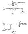
- a source 10 emits a beam of polarized light in a reference arm 11 and a measurement arm 12.
- the arms 11 and 12 are coupled to a reading system and allow a interferometric measurement.
- the arm 11 of the interferometric assembly serves as a reference.
- a transducer element 13 is located in the measurement arm 12.
- the optical fiber is generally interrupted and coupled to an external system itself sensitive to displacement.
- These sensors seem more particularly suitable for small displacement measurements (a few hundred micrometers).
- Other interferometric or non-interferometric sensors use a sensitive element placed at the end of the fiber (Fizeau micro interferometers or system varying the flux transmitted or reflected).
- Such a sensor is shown in FIG. 2 with a source 10 emitting a light beam in an optical fiber 14. The light is reflected by an element 15 sensitive to movement towards a fiber 16 and a detector 17.
- FIG. 2 With a source 10 emitting a light beam in an optical fiber 14. The light is reflected by an element 15 sensitive to movement towards a fiber 16 and a detector 17.
- such sensors make it possible to measure only small displacements.
- the invention relates to a sensor allowing displacement measurements of large amplitudes, reaching ten centimeters for example with high relative precision (10 ⁇ 3 for example).
- the senor can be located at a distance (several hundred meters for example) from the interferometric measurement system without the faults inherent in the bonding fiber having an influence on the measurement.
- the system of the invention makes it possible to multiplex several sensors on the same measurement fiber, thus allowing several measurements of the same type or not.
- the invention therefore relates to a fiber optic displacement sensor, characterized in that it comprises: - an optical source of light linearly polarized along an axis of polarization; a birefringent optical fiber, one input face of which is coupled to the optical source with a birefringence axis aligned with the axis of polarization of the light emitted by the optical source, this optical fiber having at least two localized coupling points, fixed and spaced by a determined distance; - at least one mobile coupling means making it possible to induce coupling, at a mobile coupling point of the fiber, between the two axes of polarization of the fiber; - an analysis means coupled to the fiber output and making it possible to detect interference due to the different couplings induced in the fiber.
- This sensor mainly consists of a single-mode optical fiber 2 with linear polarization conservation on which two coupling points A and B have been made between the two axes of slow and rapid propagation of the birefringent fiber.
- the two coupling points A and B are fixed and delimit a segment LM of fiber useful for the measurement to determine the relative positions of a third mobile coupling point M located on this segment. Measuring the relative distances separating the mobile coupling point from the fixed coupling points makes it possible to measure the absolute displacement of the mobile coupling point.
- the variations in temperature cause more or less significant variations in the birefringence of the fibers, which modifies the differences in optical path of the polarized waves which propagate there, thus virtually modifying the length separating two consecutive coupling points. Measuring the two differences in adjacent and complementary optical paths defined by the three coupling points makes it possible to measure length by overcoming temperature problems. Fibers with linear polarization conservation which are very little sensitive to temperature can be produced.
- a single mode fiber with linear polarization conservation such as fiber 2 is by creating a strong elasto-optical birefringence from an area creating intrinsic stresses, in a single mode fiber.
- a classic example of such a fiber with the following structure two highly doped bars are placed on each side of the heart. At fiberizing, the different glasses are first viscous and then solidify. By cooling down to room temperature the doped bars which have a coefficient of thermal expansion much higher than that of the rest of the structure, contract and therefore place the region of the heart in extension stress. By elasto-optical effect this constraint creates birefringence.
- Birefringent fibers can be obtained with a heart of elliptical shape.
- the dependence of birefringence as a function of temperature is less in these fibers.
- This birefringence is often defined by the beat length L B , ie the length at the end of which the polarizations along the two neutral axes of the fiber, orthogonal, are phase shifted by 2 ⁇ Radians.
- This length is typically of the order of 1 to 5 mm.
- Fiber 2 therefore has two neutral axes X and Y.
- one of the axes, X for example, corresponds to the slow propagation axis and the other axis (Y) corresponds to the rapid propagation axis.
- Source 1 emits a beam of linearly polarized light and is coupled to fiber 2 so that light either polarized, at the input of the fiber in a polarization direction Py E which is parallel to a neutral axis of the fiber.
- this direction of polarization Py E is directed along the axis Y which is, for example, the fast axis of the fiber.
- the fixed coupling points A and B can be produced in different ways.
- An interesting method is to twist the fiber elastically and then heat it locally using an electric arc, a blowtorch, or a laser source. The torsion is relaxed at the heating point, thus creating a rotation of the neutral axes and therefore a localized coupling, without inducing losses since the core of the fiber is not interrupted.
- These coupling points can be created by other methods provided that they are created at fixed points, well located and that they do not destroy the continuity of the core of this fiber.
- the mobile coupling point M can be created by an inducing device secured to the mobile element whose displacement is to be measured.
- An interesting solution is the use of the Faraday effect, which locally induces a polarization rotation equivalent to a coupling point. This solution has the advantage of being non-contact and reversible.
- the Faraday rotation is obtained using an electromagnet (or a permanent magnet), whose air gap of the order of a few hundred micrometers makes it possible to obtain field lines collinear with the optical fiber.
- the interferometric re-reading method used and described below does not do not require strong coupling points, which makes it possible to use usual magnetic fields.
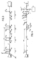
- Figure 5 illustrates this Faraday rotation by an angle ⁇ of the polarization.
- a polarized wave according to EO y direction undergoes a rotation angle ⁇ over a length subjected to the magnetic field H.
- the E1 polarized wave is then divided into a polarized wave and polarized wave E1y E1X according to the two neutral axes of fiber 1.
- the source 1 therefore emits, in the fiber 2, a wave train, whose polarization Py E , in the zone ZA before reaching the coupling point A, is directed along the fast axis Y.
- the primary wave train (Py M2 ) is ahead of the second coupled wave train (Px M2 ), which is ahead of the first train of d 'coupled wave (Px A2 ).
- the wave train Py M2 gives rise to the place primary wave train Py BO and a coupled wave train Px BO .
- the primary wave train Py B3 is ahead of the third coupled wave train Px B3 created at the second fixed coupling point B, which is ahead of the second coupled wave train Px M3 which was created at the mobile coupling point M, this second coupled wave train Px M3 itself being ahead of the first coupled wave train Px A3 which was created at the first point fixed coupling A.
- the detector 3 thus receives these four wave trains. It detects the positions in time of these different wave trains and deduces therefrom the relative position of the second coupled wave train Px M3 relative to the first coupled wave train Px A3 and to the third coupled wave train Px B3 . This relative position gives the relative position of the mobile coupling point M with respect to the two fixed coupling points A and B, which makes it possible to locate the point M on the length of optical fiber LM.
- the detector 3 makes it possible to carry out a measurement of the interferometric type.
- the linear birefringence B of an optical fiber is given by means of the beat length Lb (fiber length necessary to obtain a phase shift of 2 ⁇ between the two modes of propagation of crossed polarizations).
- Lb beat length necessary to obtain a phase shift of 2 ⁇ between the two modes of propagation of crossed polarizations.
- a light source having a low coherence (of the order of a few tens of wavelengths for example) is provided, which makes it possible to measure displacements of the order of a few tens of beat lengths.
- the visualization (in the sense of interferometric measurement) of the three coupling points necessary for the measurement of the sensor is obtained by the use of a light source having a low coherence.
- FIG. 4 shows a detailed embodiment of the displacement sensor according to the invention.
- Source 1 emits a linearly polarized wave Py in fiber 1. This wave undergoes a first coupling at the fixed coupling point A, then a second coupling at the mobile coupling point M, and finally a third coupling at the fixed coupling point B. The effect of these different couplings is as described in relation to FIG. 3.
- the primary and coupled wave trains are readjusted according to the same state of polarization on a fiber 2 ′ of offset to the detector 3.
- the disturbing effects which can influence the fiber 2 ′ have no effect on the delays induced, in the fiber element 2, on the coupled wave trains.
- a polarizer 4 coupled to the fiber 2 ′ and placed at the input of the detector 3 then makes it possible to eliminate the disturbing effects.
- the polarizer 4 thus transmits four wave trains whose polarization directions Py B4 , Px B4 , Px M4 and Px A4 are parallel.
- wave trains are sent to a Michelson type interferometer having a semi-reflecting input mirror 5 which retransmits the light coming from the polarizer 3 to a mirror 6 and a mirror 7. After reflection by these mirrors 6 and 7, the wave trains are returned to a measurement arm 9 where they interfere.
- a measuring device 8 makes it possible to measure the interference between the wave trains reflected by the two mirrors 6 and 7.
- the mirror 6 is movable in translation in the direction of the light beam coming from the semi-reflecting mirror 5.
- the optical paths comprising the mirrors 6 and 7 can therefore be of different lengths and their offset makes it possible to bring the wave trains of coincidence. way to create interference.
- FIG. 6 represents, by way of example, on line a, the wave trains retransmitted by the mirror 6 and, on line b, the wave trains retransmitted by the mirror 7.
- the difference in length of the optical paths in the interferometer is linked to the delay between the two primary (Py B4 ) and coupled (Px B4 ) wave trains.
- the location of the other Px A4 and Px M4 coupled wave trains is done in the same way.
- the relative position of the Px M4 coupled wave train with respect to the Px A4 wave trains and Px B4 provides the relative position of the mobile coupling point M with respect to the fixed coupling points A and B.
- a movable mirror 6 has been provided, however any means making it possible to make the length of the optical path variable in at least one arm of the interferometer could be suitable.
- the displacement sensor of the invention therefore uses the properties of single-mode optical fibers with linear polarization conservation and those linked to the presence of points of controlled and longitudinally distributed polarization couplings. Access to the displacement measurement is obtained by an interferometric type reading.
- An elementary sensor consists of a segment of birefringent single-mode optical fiber bounded by two intrinsic coupling points (to the fiber) and of a mobile coupling point located on this segment.
- the extrinsic mobile coupling point is non-contact and is, for example, induced by the Faraday effect.
- the reading process is interferometric, and the light source used has poor coherence. It is important that the coherence length of the source in the optical fiber 2 is less than the distance which separates two adjacent coupling points. In particular in the context of measuring the displacement of the mobile point M, the coherence length of the source 1 should be less than the minimum distance that can separate this mobile point M from the nearest fixed point A or B.
- the distance separating the two fixed coupling points A and B must be greater than twice the coherence length of the source increased by the maximum distance by which the mobile point M must be able to move.
- the invention is also applicable to a sensor in which the point M is not located between the points A and B.
- the distance separating the fixed points A and B as well as that separating the mobile point M from the fixed point ( A or B) the closest must be greater than the coherence length of the source.
- the interferometric reading of the relative positions of the mobile coupling point with respect to the fixed coupling points makes it possible to measure the displacement and to overcome any possible effect of the temperature on the birefringence of the fiber used.
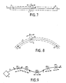
- the sensor of the invention is applicable to a linear displacement sensor as shown in FIG. 7.
- the fiber 2 is rectilinear between the fixed coupling points A and B.
- the device 4 causing a coupling at the point M of the fiber 2 is movable rectilinearly according to arrow Z.
- the sensor of the invention therefore measures a linear displacement.
- the sensor of the invention is also applicable to an angular displacement sensor as shown in FIG. 8.
- the fiber is bent between the fixed coupling points A and B.
- the device 4 causing coupling at the point M of the fiber 2 is movable along the axis of the fiber as indicated by arrow Z.
- the sensor of the invention therefore measures an angular displacement which can be translated, if necessary into an angle of rotation.
- the sensor of the invention can also be applied to a sensor comprising several movable coupling points.
- a sensor comprising several movable coupling points.
- Each portion of fiber delimited by these fixed coupling points may include a single mobile coupling point M1, M2 , M3 or even several mobile coupling points, such as M4 and M5 for the portion between the fixed coupling points D and E.
- the coherence length of the source 1 in the fiber 2 must be less than the distance between two adjacent fixed or mobile coupling points of the fiber 2.
- the sensor of the invention thus presents, in addition to the relative precision of the displacement measurement for example (10 ⁇ 3), a possibility of multiplexing measurements. In addition, it allows the sensor (a portion of fiber located between the fixed coupling points A and B) to be moved at a great distance (several hundred meters) from detector 3 (interferometer).
Landscapes
- Physics & Mathematics (AREA)
- General Physics & Mathematics (AREA)
- Length Measuring Devices By Optical Means (AREA)
- Optical Transform (AREA)
- Instruments For Measurement Of Length By Optical Means (AREA)
- Optical Couplings Of Light Guides (AREA)
Applications Claiming Priority (2)
| Application Number | Priority Date | Filing Date | Title |
|---|---|---|---|
| FR8805347A FR2630537B1 (fr) | 1988-04-22 | 1988-04-22 | Capteur de deplacement a fibre optique |
| FR8805347 | 1988-04-22 |
Publications (2)
| Publication Number | Publication Date |
|---|---|
| EP0338902A1 true EP0338902A1 (de) | 1989-10-25 |
| EP0338902B1 EP0338902B1 (de) | 1992-06-03 |
Family
ID=9365567
Family Applications (1)
| Application Number | Title | Priority Date | Filing Date |
|---|---|---|---|
| EP89401034A Expired - Lifetime EP0338902B1 (de) | 1988-04-22 | 1989-04-14 | Faseroptischer Versetzungssensor |
Country Status (5)
| Country | Link |
|---|---|
| US (1) | US4926040A (de) |
| EP (1) | EP0338902B1 (de) |
| JP (1) | JPH01318903A (de) |
| DE (1) | DE68901681T2 (de) |
| FR (1) | FR2630537B1 (de) |
Cited By (1)
| Publication number | Priority date | Publication date | Assignee | Title |
|---|---|---|---|---|
| FR2656095A1 (fr) * | 1989-12-19 | 1991-06-21 | Thomson Csf | Capteur a fibre optique. |
Families Citing this family (5)
| Publication number | Priority date | Publication date | Assignee | Title |
|---|---|---|---|---|
| AT397307B (de) * | 1990-03-02 | 1994-03-25 | Tabarelli Werner | Interferometer insbesondere zur längenmessung |
| FR2683053B1 (fr) * | 1991-10-29 | 1994-10-07 | Thomson Csf | Fibre optique et procede de fabrication. |
| FR2706606B1 (fr) * | 1993-06-15 | 1995-07-21 | Thomson Csf | Capteur à fibre optique reconfigurable. |
| FR2706607B1 (fr) * | 1993-06-15 | 1995-07-21 | Thomson Csf | Capteur de température multipoints reconfigurable. |
| US7120323B2 (en) * | 2000-08-02 | 2006-10-10 | Kvh Industries, Inc. | Reduction of linear birefringence in circular-cored single-mode fiber |
Citations (3)
| Publication number | Priority date | Publication date | Assignee | Title |
|---|---|---|---|---|
| US4342907A (en) * | 1977-12-12 | 1982-08-03 | Pedro B. Macedo | Optical sensing apparatus and method |
| EP0143583A2 (de) * | 1983-11-30 | 1985-06-05 | The Board Of Trustees Of The Leland Stanford Junior University | Faseroptischer Modenkoppler |
| GB2184539A (en) * | 1985-12-20 | 1987-06-24 | Rosemount Ltd | Light attenuation sensing apparatus |
Family Cites Families (4)
| Publication number | Priority date | Publication date | Assignee | Title |
|---|---|---|---|---|
| JPS5621004A (en) * | 1979-07-30 | 1981-02-27 | Toshiba Corp | Optical sensing system |
| US4572949A (en) * | 1982-04-14 | 1986-02-25 | The Board Of Trustees Of The Leland Stanford Junior University | Fiber optic sensor for detecting very small displacements of a surface |
| US4652744A (en) * | 1982-04-14 | 1987-03-24 | The Board Of Trustees Of The Leland Stanford Junior University | Fiber optic sensor for detecting very small displacements of a surface |
| US4753529A (en) * | 1986-06-23 | 1988-06-28 | Litton Systems, Inc. | Apparatus and method for precision adjustment of interferometer pathlength difference |
-
1988
- 1988-04-22 FR FR8805347A patent/FR2630537B1/fr not_active Expired - Lifetime
-
1989
- 1989-04-14 EP EP89401034A patent/EP0338902B1/de not_active Expired - Lifetime
- 1989-04-14 DE DE8989401034T patent/DE68901681T2/de not_active Expired - Lifetime
- 1989-04-18 US US07/339,792 patent/US4926040A/en not_active Expired - Fee Related
- 1989-04-21 JP JP1103327A patent/JPH01318903A/ja active Pending
Patent Citations (3)
| Publication number | Priority date | Publication date | Assignee | Title |
|---|---|---|---|---|
| US4342907A (en) * | 1977-12-12 | 1982-08-03 | Pedro B. Macedo | Optical sensing apparatus and method |
| EP0143583A2 (de) * | 1983-11-30 | 1985-06-05 | The Board Of Trustees Of The Leland Stanford Junior University | Faseroptischer Modenkoppler |
| GB2184539A (en) * | 1985-12-20 | 1987-06-24 | Rosemount Ltd | Light attenuation sensing apparatus |
Non-Patent Citations (1)
| Title |
|---|
| IBM TECHNICAL DISCLOSURE BULLETIN, vol. 27, no. 6, novembre 1984, page 3622, New York, US; R.T. HODGSON et al.: "Position sensor using fiber-optic interferometer" * |
Cited By (3)
| Publication number | Priority date | Publication date | Assignee | Title |
|---|---|---|---|---|
| FR2656095A1 (fr) * | 1989-12-19 | 1991-06-21 | Thomson Csf | Capteur a fibre optique. |
| EP0434504A1 (de) * | 1989-12-19 | 1991-06-26 | Thomson-Csf | Fiberoptischer Messwandler |
| US5064270A (en) * | 1989-12-19 | 1991-11-12 | Thomson-Csf | Optical fiber sensor |
Also Published As
| Publication number | Publication date |
|---|---|
| FR2630537A1 (fr) | 1989-10-27 |
| EP0338902B1 (de) | 1992-06-03 |
| FR2630537B1 (fr) | 1990-07-13 |
| JPH01318903A (ja) | 1989-12-25 |
| US4926040A (en) | 1990-05-15 |
| DE68901681T2 (de) | 1992-12-10 |
| DE68901681D1 (de) | 1992-07-09 |
Similar Documents
| Publication | Publication Date | Title |
|---|---|---|
| US11002594B2 (en) | Method and apparatus for distributed sensing | |
| CA2612385C (en) | Fiber optic temperature and pressure sensor and system incorporating same | |
| AU777637B2 (en) | Fiber-optic current sensor | |
| US6847453B2 (en) | All fiber autocorrelator | |
| US5359405A (en) | Hybrid fiber optic sensor including a lead out optical fiber having a remote reflective end | |
| EP0434504A1 (de) | Fiberoptischer Messwandler | |
| US5946429A (en) | Time-division multiplexing of polarization-insensitive fiber optic michelson interferometric sensor | |
| FR2626367A1 (fr) | Capteur de temperature multipoints a fibre optique | |
| EP1175599B1 (de) | Verfahren und vorrichtung zur erhöhung des dynamikbereichs, der empfindlichkeit, der genauigkeit und der auflösung in faseroptischen sensorsystemen | |
| EP0120737B1 (de) | Faseroptischer Wasserschallempfänger | |
| CN105588661B (zh) | 一种利用保偏光纤光栅实现单点及区域温度同时测量的装置 | |
| EP0078731B1 (de) | Interferometrische Magnetfeldmessvorrichtung und Strommessgerät mit dieser Vorrichtung | |
| Yu et al. | Distributed measurement of polarization characteristics for a multifunctional integrated optical chip: A review | |
| EP0338902B1 (de) | Faseroptischer Versetzungssensor | |
| CN100338449C (zh) | 反射型保偏光纤温度传感器 | |
| Rao et al. | Principles of fiber-optic interferometry | |
| Yuan et al. | Range extension of the optical delay line in white light interferometry | |
| RU2147728C1 (ru) | Интерферометрическое устройство для бесконтактного измерения толщины | |
| Yuan et al. | Design of a fiber-optic quasi-distributed strain sensors ring network based on a white-light interferometric multiplexing technique | |
| Yuan et al. | Enhancement of multiplexing capability of low-coherence interferometric fiber sensor array by use of a loop topology | |
| dos Reis | Study and Development of an Interrogation System for Fabry Perot Cavity Sensors | |
| Sinha et al. | Acoustically scanned low-coherence interrogated simultaneous measurement of absolute strain and temperature using highly birefringent fibers | |
| JPS60129632A (ja) | 光フアイバ−センサ | |
| JPS6055305A (ja) | ツインコア光フアイバ | |
| Wang et al. | Advances in sapphire optical fiber sensors |
Legal Events
| Date | Code | Title | Description |
|---|---|---|---|
| PUAI | Public reference made under article 153(3) epc to a published international application that has entered the european phase |
Free format text: ORIGINAL CODE: 0009012 |
|
| AK | Designated contracting states |
Kind code of ref document: A1 Designated state(s): DE GB IT NL SE |
|
| 17P | Request for examination filed |
Effective date: 19900117 |
|
| 17Q | First examination report despatched |
Effective date: 19910110 |
|
| GRAA | (expected) grant |
Free format text: ORIGINAL CODE: 0009210 |
|
| AK | Designated contracting states |
Kind code of ref document: B1 Designated state(s): DE GB IT NL SE |
|
| ITF | It: translation for a ep patent filed | ||
| REF | Corresponds to: |
Ref document number: 68901681 Country of ref document: DE Date of ref document: 19920709 |
|
| GBT | Gb: translation of ep patent filed (gb section 77(6)(a)/1977) | ||
| PLBE | No opposition filed within time limit |
Free format text: ORIGINAL CODE: 0009261 |
|
| STAA | Information on the status of an ep patent application or granted ep patent |
Free format text: STATUS: NO OPPOSITION FILED WITHIN TIME LIMIT |
|
| PG25 | Lapsed in a contracting state [announced via postgrant information from national office to epo] |
Ref country code: GB Effective date: 19930414 |
|
| PG25 | Lapsed in a contracting state [announced via postgrant information from national office to epo] |
Ref country code: SE Effective date: 19930415 |
|
| 26N | No opposition filed | ||
| PG25 | Lapsed in a contracting state [announced via postgrant information from national office to epo] |
Ref country code: NL Effective date: 19931101 |
|
| GBPC | Gb: european patent ceased through non-payment of renewal fee |
Effective date: 19930414 |
|
| NLV4 | Nl: lapsed or anulled due to non-payment of the annual fee | ||
| PG25 | Lapsed in a contracting state [announced via postgrant information from national office to epo] |
Ref country code: DE Effective date: 19940101 |
|
| EUG | Se: european patent has lapsed |
Ref document number: 89401034.7 Effective date: 19931110 |
|
| PG25 | Lapsed in a contracting state [announced via postgrant information from national office to epo] |
Ref country code: IT Free format text: LAPSE BECAUSE OF NON-PAYMENT OF DUE FEES;WARNING: LAPSES OF ITALIAN PATENTS WITH EFFECTIVE DATE BEFORE 2007 MAY HAVE OCCURRED AT ANY TIME BEFORE 2007. THE CORRECT EFFECTIVE DATE MAY BE DIFFERENT FROM THE ONE RECORDED. Effective date: 20050414 |