EP0338537A2 - Unitized multi-layered gasket and method of making same - Google Patents
Unitized multi-layered gasket and method of making same Download PDFInfo
- Publication number
- EP0338537A2 EP0338537A2 EP89107044A EP89107044A EP0338537A2 EP 0338537 A2 EP0338537 A2 EP 0338537A2 EP 89107044 A EP89107044 A EP 89107044A EP 89107044 A EP89107044 A EP 89107044A EP 0338537 A2 EP0338537 A2 EP 0338537A2
- Authority
- EP
- European Patent Office
- Prior art keywords
- gasket
- sections
- layered
- section
- folded
- Prior art date
- Legal status (The legal status is an assumption and is not a legal conclusion. Google has not performed a legal analysis and makes no representation as to the accuracy of the status listed.)
- Granted
Links
Images


Classifications
-
- F—MECHANICAL ENGINEERING; LIGHTING; HEATING; WEAPONS; BLASTING
- F16—ENGINEERING ELEMENTS AND UNITS; GENERAL MEASURES FOR PRODUCING AND MAINTAINING EFFECTIVE FUNCTIONING OF MACHINES OR INSTALLATIONS; THERMAL INSULATION IN GENERAL
- F16J—PISTONS; CYLINDERS; SEALINGS
- F16J15/00—Sealings
- F16J15/02—Sealings between relatively-stationary surfaces
- F16J15/06—Sealings between relatively-stationary surfaces with solid packing compressed between sealing surfaces
- F16J15/08—Sealings between relatively-stationary surfaces with solid packing compressed between sealing surfaces with exclusively metal packing
- F16J15/0818—Flat gaskets
- F16J15/0825—Flat gaskets laminated
-
- F—MECHANICAL ENGINEERING; LIGHTING; HEATING; WEAPONS; BLASTING
- F16—ENGINEERING ELEMENTS AND UNITS; GENERAL MEASURES FOR PRODUCING AND MAINTAINING EFFECTIVE FUNCTIONING OF MACHINES OR INSTALLATIONS; THERMAL INSULATION IN GENERAL
- F16J—PISTONS; CYLINDERS; SEALINGS
- F16J15/00—Sealings
- F16J15/02—Sealings between relatively-stationary surfaces
- F16J15/06—Sealings between relatively-stationary surfaces with solid packing compressed between sealing surfaces
- F16J15/08—Sealings between relatively-stationary surfaces with solid packing compressed between sealing surfaces with exclusively metal packing
- F16J15/0818—Flat gaskets
- F16J2015/0837—Flat gaskets with an edge portion folded over a second plate or shim
-
- F—MECHANICAL ENGINEERING; LIGHTING; HEATING; WEAPONS; BLASTING
- F16—ENGINEERING ELEMENTS AND UNITS; GENERAL MEASURES FOR PRODUCING AND MAINTAINING EFFECTIVE FUNCTIONING OF MACHINES OR INSTALLATIONS; THERMAL INSULATION IN GENERAL
- F16J—PISTONS; CYLINDERS; SEALINGS
- F16J15/00—Sealings
- F16J15/02—Sealings between relatively-stationary surfaces
- F16J15/06—Sealings between relatively-stationary surfaces with solid packing compressed between sealing surfaces
- F16J15/08—Sealings between relatively-stationary surfaces with solid packing compressed between sealing surfaces with exclusively metal packing
- F16J15/0818—Flat gaskets
- F16J2015/0843—Flat gaskets with an edge portion folded over the plate itself
-
- F—MECHANICAL ENGINEERING; LIGHTING; HEATING; WEAPONS; BLASTING
- F16—ENGINEERING ELEMENTS AND UNITS; GENERAL MEASURES FOR PRODUCING AND MAINTAINING EFFECTIVE FUNCTIONING OF MACHINES OR INSTALLATIONS; THERMAL INSULATION IN GENERAL
- F16J—PISTONS; CYLINDERS; SEALINGS
- F16J15/00—Sealings
- F16J15/02—Sealings between relatively-stationary surfaces
- F16J15/06—Sealings between relatively-stationary surfaces with solid packing compressed between sealing surfaces
- F16J15/08—Sealings between relatively-stationary surfaces with solid packing compressed between sealing surfaces with exclusively metal packing
- F16J15/0818—Flat gaskets
- F16J2015/085—Flat gaskets without fold over
-
- Y—GENERAL TAGGING OF NEW TECHNOLOGICAL DEVELOPMENTS; GENERAL TAGGING OF CROSS-SECTIONAL TECHNOLOGIES SPANNING OVER SEVERAL SECTIONS OF THE IPC; TECHNICAL SUBJECTS COVERED BY FORMER USPC CROSS-REFERENCE ART COLLECTIONS [XRACs] AND DIGESTS
- Y10—TECHNICAL SUBJECTS COVERED BY FORMER USPC
- Y10S—TECHNICAL SUBJECTS COVERED BY FORMER USPC CROSS-REFERENCE ART COLLECTIONS [XRACs] AND DIGESTS
- Y10S277/00—Seal for a joint or juncture
- Y10S277/924—Deformation, material removal, or molding for manufacture of seal
-
- Y—GENERAL TAGGING OF NEW TECHNOLOGICAL DEVELOPMENTS; GENERAL TAGGING OF CROSS-SECTIONAL TECHNOLOGIES SPANNING OVER SEVERAL SECTIONS OF THE IPC; TECHNICAL SUBJECTS COVERED BY FORMER USPC CROSS-REFERENCE ART COLLECTIONS [XRACs] AND DIGESTS
- Y10—TECHNICAL SUBJECTS COVERED BY FORMER USPC
- Y10T—TECHNICAL SUBJECTS COVERED BY FORMER US CLASSIFICATION
- Y10T29/00—Metal working
- Y10T29/49—Method of mechanical manufacture
- Y10T29/49229—Prime mover or fluid pump making
- Y10T29/49297—Seal or packing making
Definitions
- This invention generally relates to gasket assemblies and, more particularly, to a unitized gasket, especially for internal combustion engines, formed of multi-layered construction and a process for making same.
- mating surfaces or pairs of surfaces to be sealed such as an automotive engine block and a mating surface on an exhaust manifold
- Multi-layer gasket assemblies are becoming more popular for use with automobile engines.
- Such a gasket assembly is comprised of two or more layered gasket pieces which are typically welded or riveted to each other.
- Each gasket piece may be similar in size and overall configuration to other gasket pieces used in the same assembly.
- Each piece can, however, include details which distinguish it from the other gasket pieces. That is, albeit similarly outlined or configured, one gasket piece may have one or more embossments provided thereon while another similarly outlined gasket piece in the same gasket assembly may have different embossments or other features provided thereon. Additionally, for example, one gasket piece in the assembly may be substantially flat while another gasket piece in the same assembly can include a flow tube extending from a source opening provided in that gasket piece.
- Production of multi-layered gaskets typically comprises multiple steps or manufacturing processes.
- these individual gasket pieces are separately processed, as by heat treating, etc.
- the individualized gasket pieces are layered in a specific order and are, subsequently, assembled in that order.
- the individual pieces forming the gasket assembly are usually held together as an assemblage, as with rivets or spot welding. After the separate gasket pieces are joined together as a complete assembly, the resultant gasket is inspected for accuracy and compliance.
- each piece comprising the gasket assembly is layered in its proper order. Otherwise, the gasket assembly is likely to fail. Because the pieces comprising the gasket assembly may all be similar in size and overall configuration, assembly of the gasket can easily be done incorrectly. That is, gasket pieces may be arranged in an improperly layered order. Alternatively, and because the gasket pieces are individually manufactured, placed together, and then assembled, two of the same gasket pieces may be inadvertently assembled together. A myriad of other inadvertent yet incorrect combinations of gasket pieces is conceivable. Although inadvertent, such improper combinations or arrangements of the various gasket pieces can result in gasket failure.
- a multi-layered gasket comprising a gasket body including multiple interconnected gasket sections.
- the gasket body includes at least two gasket sections, with each gasket section defining a service opening and at least one relatively small aperture.
- a peripheral edge of a first of the gasket sections is interconnected with a peripheral edge of a second of the gasket sections in a manner allowing the first gasket section to be folded into an overlying engaging relationship with the second gasket section, with the aperture and service openings being in alignment.
- first and second gasket sections are integrally formed, as of metal, and are general coextensive. Moreover, at least one of the gasket sections defines a projecting embossment encircling the service opening defined by the gasket section.
- One or more bridges which can be integral extensions of one of the gasket sections, serve to interconnect the gasket sections.
- the gasket body includes a third gasket section. Bendable metallic bridges interconnect this third gasket section with the gasket body.
- the three gasket sections can be integrally formed along with the bridges interconnecting the gasket sections.
- Each gasket section can also include indicia for indicating an overlying relationship order for the gasket sections.
- the three gasket sections can be folded into an overlying relationship with each other in an accordion-like fashion with the apertures in the overlying sections being substantially aligned with each other.
- the various gasket sections are each foldable along fold lines defined by the gasket body at peripheral edges of the gasket sections after the sections are folded upon each other.
- one or more bendable closing tabs extend from at least one of the gasket sections. If so desired, such closing tabs can be integrally formed with one of the gasket sections. Such closing tabs can be manipulated to retain such gasket sections in an overlying engaging relationship relative to one another.
- a method for making such a gasket involves providing multiple interconnected gasket sections with each gasket section defining a service opening and a relatively small aperture.
- a preferred method involves providing at least two interconnected gasket sections.
- An alternative method involves providing at least three interconnected gasket sections.
- the gasket sections may be integrally formed of metal.
- Making a unitized multi-layered gasket according to the present invention further involves folding a first of the gasket sections into an overlying engaging relationship with a second of the gasket sections.
- the gasket sections are folded along a fold line defined at a peripheral edge of each gasket section after one gasket section is folded upon the other gasket section.
- the sections are preferably folded in an accordion relationship relative to each other.
- the making of a multi-layered gasket can further involve providing an encircling embossment about each of the service openings on at least one of the gasket sections.
- the encircling embossments are formed on the gasket sections before they are folded upon each other.
- steps involved with a method of forming a unitized gasket according to the present invention involve providing bendable closing tabs on at least one of the gasket sections and closing the tabs. Closing the tabs serves to retain the gasket sections in the folded accordion relationship relative to each other.
- each gasket Because the gasket sections are interconnected to each other, they cannot become separated from each other. As such, the above-contemplated design assures repeatability and also proper gasket construction. That is, because the sections comprising the gasket are inseparable from one another, only the proper pieces are incorporated in each gasket assembly. Therefore, each gasket will repeatably be comprised of the same component pieces.
- each gasket section is interconnected, the layered orientation of each gasket section is fixed with respect to the other gasket sections. Because each section is folded or bent upon its adjacent gasket section, a proper layering order is assured.
- the gasket sections may be provided with indicia indicating an overlying relationship order for the gasket sections.
- the manufacturing method involved with the present invention is most efficient and minimizes human error and labor involvement.
- a continuous roll of gasket material may be fed into a machine and a finished gasket would be automatically processed and formed thereby avoiding the possibility of inadvertent assemblage.
- the contemplated design minimizes in-process inventory, labor, material handling, and warehousing costs.
- the gasket sections are, as is contemplated, integrally formed by a progressive die assembly from a single sheet of rolled stock, there is also a savings of set-up time for the machinery used to stamp or blank out the gasket sections.
- the design contemplated by the instant invention would require only one die assembly.
- die cost would also be lower when only one die assembly is used as compared to multiple die assemblies which would be required if separate gasket blanks were to be used in making a gasket.
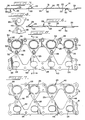
- FIGURE 1 a unitized multi-layered gasket 10 arranged in an unfolded configuration.
- the gasket 10 When assembled in its operative condition, the gasket 10 is adapted to be disposed, in known manner, between a pair of surfaces to be sealed, such as between an engine block and a multiported manifold of an internal combustion engine and is compressed therebetween.
- the gasket 10 comprises a gasket body 12 including multiple gasket sections 14, 16 and 18. Although three gasket sections are illustrated, it will be appreciated and understood that more than three gasket sections could be provided without departing from the spirit and scope of this invention. In the preferred embodiment, each gasket section is formed of metal.
- Each gasket section has certain features which are common amongst them. Those features which are common will be described referring to gasket section 14 but with the understanding that the other gasket sections include the same or similar features.
- Each gasket section defines a first, generally planar main surface 20 (FIG. 1) and a second generally planar main surface 22 (FIG. 2). Surfaces 20 and 22 are generally parallel to each other. Where, as here, there are at least three gasket sections, it is preferred that each gasket section be about 0.2032 mm (about 0.008 inch) thick, but the gasket sections may range in thickness from about 0.127 mm (about 0.005 inch) to about 0.508 mm (about 0.020 inch).
- each gasket section defines one or more relatively large, clear-through service openings 24 and one or more relatively small apertures 26.
- the smaller apertures 26 may define bolt holes through which clamping bolts (not shown) may pass.
- the gasket body 12 is preferably die cut or blanked out, such as with a stamping machine, punch press, or other suitable form of equipment to provide the requisite configuration to the gasket body 12.
- multiple gasket sections 14, 16 and 18 are integrally formed from a single sheet of material during the stamping or punching process. As such, each section is of the same material but can be different in shape. The sections may be continuous or may be segmental.
- gasket section 14 defines encircling embossments 28 arranged about each service opening 24.
- Embossments 28 are formed in a known manner as by pressing them into the planar sheet of which gasket section 14 may be formed.
- the sealing embossments may be of varying depths and dimensions depending upon gasket's use.
- embossments 28 comprise a projecting portion or projection 30 extending outwardly from the main or major surface 22, and a corresponding indentation, recess or cavity 32 which extends inward from major or main surface 20.
- gasket section 14 further defines encircling embossments 34 arranged about certain of the bolt holes 26.
- the embossments 34 are formed in a known manner as by pressing them into the planar sheet from which the gasket section may be formed.
- the sealing embossments 34 may be of varying depths and dimensions depending upon the gasket's use.
- embossment 34 comprises a projecting portion or projection 36 extending outwardly from major or main surface 22, and a corresponding indentation, recess, or cavity 38 which extends inward from major or main surface 20.
- embossments 34 are of similar construction.
- gasket section 16 defines encircling embossments 29 arranged about each service opening 24. Embossments 29 are formed in a similar manner to embossments 28 as by pressing them into a planar sheet of which gasket section 16 may be formed.
- embossments 29 comprise a projecting portion or projection 31 extending outwardly from the main or major surface 20, and a corresponding indentation, recess, or cavity 33 which extends inwardly from major or main surface 22.
- the embossments 29 are arranged on gasket section 16 in an inverse manner to the embossments 28 arranged on gasket section 14. As such, and as seen in FIGURE 6, when one gasket section is folded upon the other, embossments 28 and 29 are arranged in a complementary fashion.
- gasket section 18 defines a series of flow tube formations 40 which are provided to improve the flow of exhaust gases through service openings 24.
- the flow tube formations 40 comprise a bent rim 42 extending around each service opening 24 provided in section 18. As seen in FIGURE 3, each tube formation 40 extends substantially transversely away from the main or major surface 22 of gasket section 18.
- the projection 42 is formed as an integral part of gasket section 18.
- gasket section 18 further defines one or more bendable closing tabs 43 provided on an outwardly extending edge thereof.
- the bendable tabs 43 are integrally formed with the gasket section from which they protrude but such tabs could comprise separate elements.
- bendable tabs 43 could alternatively or additionally be provided on an outwardly extending edge of gasket section 14. With either embodiment, the bendable tabs 43 laterally extend away from the gasket section to which they are attached a sufficient distance to allow them to be manipulated and/or bent around the other gasket layers to secure or retain all of the layered sections in a folded engaging relationship with each other.
- the gasket sections comprising the gasket body are interconnected to each other.
- the present invention contemplates interconnecting the gasket sections in any suitable manner allowing the gasket sections to be folded into an overlying and engaging relationship with one another.
- one or more bendable connections can be used to interconnect the gasket sections to each other.
- opposed peripheral edges on gasket sections 14, 16 and 18, respectively are interconnected by a plurality of bendable bridges 48.
- relatively small bridges 48 are formed in a zone of adjacency between gasket sections 14 and 16.
- the die assemblies for punching the gasket sections are designed to configure the gasket sections to correspond to the particular application with which they find use.
- the die assemblies can be designed to provide the bridges 48 between adjacent areas of the gasket sections.
- the bridges 48 are formed as integral extensions between gasket sections.
- the bendable connections 48 between the gasket section allow one interconnected gasket section 14 to be layered or folded into an overlying engaging relationship with another interconnected gasket section 16. Because the gasket sections are interconnected, they are not separated from one another when folded upon each other. That is, the bendable bridges 48 provided at the peripheral edges of the gasket sections 14 and 16 allow gasket section 14 to be folded while maintaining integrity between gasket sections. As seen in FIGURE 6, when gasket sections 14 and 16 are folded upon each other, the respective service openings 24, the respective embossments 28 and 29, as well as the respective apertures 26 are all arranged in substantial alignment.
- the other gasket section 18 can likewise be folded into an overlying engaging relationship with the other gasket sections 14, 16, preferably in an accordion-like fashion.
- the flow tubes 40 formed as an integral part of gasket 18, transversely extend through the service openings 24 in the other gasket sections 14 and 16. That is, when the multiple gasket pieces are folded upon each other, a distal end of projection 42 extends through all layers of the gasket.
- Each gasket section may further include indicia 50 (FIGURE 8) which can be stamped or otherwise provided thereon.
- the indicia 50 are provided for indicating the desired overlying relationship order for the gasket sections.
- Associated notches 52 may be used to view the indicia when the gasket sections are folded.
- each bendable tab 43 is folded over from its extended position, indicated by dash lines in FIG. 11, to interface with gasket section 14.
- the folded tabs 43 maintain and retain the gasket sections in their overlying and engaging relationship relative one another during packing, storage and installation.
- a method of manufacture involves providing multiple interconnected gasket sections, with each gasket section defining at least one service opening and at least one relatively small aperture.
- a preferred method involves providing at least two interconnected gasket sections.
- An alternative method involves providing at least three interconnected gasket sections all of which are integrally formed of metal.
- closing tabs 43 are manipulated to retain the gasket sections in either folded relationship relative to each other.
- a preferred method of manufacture may further involve providing an embossment on at least one of the gasket sections.
- the embossment encircles the service opening defined by the gasket section.
- the embossing operation, if any, is performed on the gasket section before the gasket sections are folded upon each other.
- the embossments 28′, 29′ defined by gasket sections 14′, 16′, respectively are formed with the projecting portion of each embossment 28′, 29′ extending away from main or major surface 22′ of each gasket section and the indentation, recess, or cavity of each embossment extending inwardly from main or major surface 20′ of each gasket section.
- the projections of each embossment will extend in opposite directions and a compressible space will be provided between oppositely directed, and confronting, indentations of each embossment.
- each of the gasket sections comprising the unitized gasket are interconnected to each other, they cannot become separated from each other. Therefore, the gasket will always include a proper combination and sequence of only interconnected gasket sections. Furthermore, the gasket sections may be interconnected in a manner defining the order with which they are to be folded upon each other. As such, each gasket section will have a proper orientation relative another gasket section and relative to the unitized gasket assembly. In effect, the unitized contemplated multi-layered gasket assembly avoids the possibility of human error and inadvertent assemblage.
Abstract
Description
- This invention generally relates to gasket assemblies and, more particularly, to a unitized gasket, especially for internal combustion engines, formed of multi-layered construction and a process for making same.
- Although the mating surfaces or pairs of surfaces to be sealed, such as an automotive engine block and a mating surface on an exhaust manifold, appear to be smooth and flat, most frequently they are not sufficiently smooth to provide an effective seal. Accordingly, a gasket is required to be placed between them to provide an effective seal against escaping fluids, such as gas vapors.
- Multi-layer gasket assemblies are becoming more popular for use with automobile engines. Such a gasket assembly is comprised of two or more layered gasket pieces which are typically welded or riveted to each other. Each gasket piece may be similar in size and overall configuration to other gasket pieces used in the same assembly. Each piece can, however, include details which distinguish it from the other gasket pieces. That is, albeit similarly outlined or configured, one gasket piece may have one or more embossments provided thereon while another similarly outlined gasket piece in the same gasket assembly may have different embossments or other features provided thereon. Additionally, for example, one gasket piece in the assembly may be substantially flat while another gasket piece in the same assembly can include a flow tube extending from a source opening provided in that gasket piece.
- Production of multi-layered gaskets typically comprises multiple steps or manufacturing processes. First, because each piece comprising the gasket assembly may be uniquely designed, individualized gasket pieces are mass produced, as by a stamping or blanking process. That is, steel or other suitable gasket material is continuously fed to a machine which stamps or blanks out individual gasket pieces having specific configurations. In the next step, these individual gasket pieces are separately processed, as by heat treating, etc. Then, the individualized gasket pieces are layered in a specific order and are, subsequently, assembled in that order. The individual pieces forming the gasket assembly are usually held together as an assemblage, as with rivets or spot welding. After the separate gasket pieces are joined together as a complete assembly, the resultant gasket is inspected for accuracy and compliance.
- It is critical that each piece comprising the gasket assembly is layered in its proper order. Otherwise, the gasket assembly is likely to fail. Because the pieces comprising the gasket assembly may all be similar in size and overall configuration, assembly of the gasket can easily be done incorrectly. That is, gasket pieces may be arranged in an improperly layered order. Alternatively, and because the gasket pieces are individually manufactured, placed together, and then assembled, two of the same gasket pieces may be inadvertently assembled together. A myriad of other inadvertent yet incorrect combinations of gasket pieces is conceivable. Although inadvertent, such improper combinations or arrangements of the various gasket pieces can result in gasket failure.
- In view of the above, and in accordance with the present invention, there is provided a multi-layered gasket comprising a gasket body including multiple interconnected gasket sections. In a preferred form, the gasket body includes at least two gasket sections, with each gasket section defining a service opening and at least one relatively small aperture. A peripheral edge of a first of the gasket sections is interconnected with a peripheral edge of a second of the gasket sections in a manner allowing the first gasket section to be folded into an overlying engaging relationship with the second gasket section, with the aperture and service openings being in alignment.
- In one form, the first and second gasket sections are integrally formed, as of metal, and are general coextensive. Moreover, at least one of the gasket sections defines a projecting embossment encircling the service opening defined by the gasket section. One or more bridges, which can be integral extensions of one of the gasket sections, serve to interconnect the gasket sections.
- In another form of the invention, the gasket body includes a third gasket section. Bendable metallic bridges interconnect this third gasket section with the gasket body. Alternatively, the three gasket sections can be integrally formed along with the bridges interconnecting the gasket sections. Each gasket section can also include indicia for indicating an overlying relationship order for the gasket sections. The three gasket sections can be folded into an overlying relationship with each other in an accordion-like fashion with the apertures in the overlying sections being substantially aligned with each other. The various gasket sections are each foldable along fold lines defined by the gasket body at peripheral edges of the gasket sections after the sections are folded upon each other.
- In a preferred form of the invention, one or more bendable closing tabs extend from at least one of the gasket sections. If so desired, such closing tabs can be integrally formed with one of the gasket sections. Such closing tabs can be manipulated to retain such gasket sections in an overlying engaging relationship relative to one another.
- In accordance with the present invention, a method for making such a gasket involves providing multiple interconnected gasket sections with each gasket section defining a service opening and a relatively small aperture. A preferred method involves providing at least two interconnected gasket sections. An alternative method involves providing at least three interconnected gasket sections. The gasket sections may be integrally formed of metal.
- Making a unitized multi-layered gasket according to the present invention further involves folding a first of the gasket sections into an overlying engaging relationship with a second of the gasket sections. The gasket sections are folded along a fold line defined at a peripheral edge of each gasket section after one gasket section is folded upon the other gasket section.
- In those embodiments where three interconnected gasket sections are provided, the sections are preferably folded in an accordion relationship relative to each other.
- The making of a multi-layered gasket can further involve providing an encircling embossment about each of the service openings on at least one of the gasket sections. The encircling embossments are formed on the gasket sections before they are folded upon each other.
- Other steps involved with a method of forming a unitized gasket according to the present invention involve providing bendable closing tabs on at least one of the gasket sections and closing the tabs. Closing the tabs serves to retain the gasket sections in the folded accordion relationship relative to each other.
- Because the gasket sections are interconnected to each other, they cannot become separated from each other. As such, the above-contemplated design assures repeatability and also proper gasket construction. That is, because the sections comprising the gasket are inseparable from one another, only the proper pieces are incorporated in each gasket assembly. Therefore, each gasket will repeatably be comprised of the same component pieces.
- Moreover, because the gasket sections are interconnected, the layered orientation of each gasket section is fixed with respect to the other gasket sections. Because each section is folded or bent upon its adjacent gasket section, a proper layering order is assured. In this regard, and if desired, the gasket sections may be provided with indicia indicating an overlying relationship order for the gasket sections.
- The manufacturing method involved with the present invention is most efficient and minimizes human error and labor involvement. Thus, a continuous roll of gasket material may be fed into a machine and a finished gasket would be automatically processed and formed thereby avoiding the possibility of inadvertent assemblage. As will be understood, the contemplated design minimizes in-process inventory, labor, material handling, and warehousing costs. If the gasket sections are, as is contemplated, integrally formed by a progressive die assembly from a single sheet of rolled stock, there is also a savings of set-up time for the machinery used to stamp or blank out the gasket sections. Rather than having to use multiple presses and die assemblies for producing multiple separate blanks, the design contemplated by the instant invention would require only one die assembly. Clearly, die cost would also be lower when only one die assembly is used as compared to multiple die assemblies which would be required if separate gasket blanks were to be used in making a gasket.
- Other features and advantages of the present invention will become readily apparent from in the following detailed description, the appended drawings, and the accompanying claims.
-
- FIGURE 1 is a top plan view of a unitized multi-layered gasket embodying principles of the present invention and showing the gasket prior to folding;
- FIGURE 2 is a bottom plan view of the gasket of FIGURE 1;
- FIGURE 3 is a cross-sectional view taken along line 3-3 of FIGURE 1;
- FIGURE 4 is an enlarged view of an area encircled in FIGURE 1;
- FIGURE 5 is a top plan view of the gasket of FIGURE 1 having a first gasket section folded into an overlying and engaging relationship relative to another gasket section of the gasket;
- FIGURE 6 is a bottom plan view of the gasket shown in FIGURE 5;
- FIGURE 7 is a cross-sectional view taken substantially along line 7-7 of FIGURE 5;
- FIGURE 8 is a top plan view of the gasket of FIGURE 1 wherein each gasket section is accordion folded;
- FIGURE 9 is a bottom plan view of the gasket of FIGURE 8;
- FIGURE 10 is a cross-sectional view taken substantially along line 10-10 of FIGURE 8;
- FIGURE 11 is an enlarged fragmentary cross-sectional view taken substantially along line 11-11 of FIGURE 8; and
- FIGURE 12 is a view like FIGURE 10 but of a further embodiment of this invention.
- While the present invention is susceptible of embodiment in various forms, there is shown in the drawings a presently preferred embodiment hereinafter described, with the understanding that the present disclosure is to be considered as an exemplification of the invention and is not intended to limit the invention to the specific embodiment illustrated.
- Referring now to the drawings, wherein like reference numerals indicate like parts throughout the several views, there is shown in FIGURE 1 a unitized
multi-layered gasket 10 arranged in an unfolded configuration. When assembled in its operative condition, thegasket 10 is adapted to be disposed, in known manner, between a pair of surfaces to be sealed, such as between an engine block and a multiported manifold of an internal combustion engine and is compressed therebetween. The details of the engine per se, which may be of various forms, form no part of the present invention, except that a gasket embodying the principles of the present invention will be configured as dictated by the particular engine with which it is to be used, and will be proportioned to accommodate to the openings and surfaces in the block and manifold with which the gasket assembly is to be used and which the gasket assembly is to seal. - Referring now to FIGURES 1 and 2, the
gasket 10 comprises agasket body 12 includingmultiple gasket sections - Each gasket section has certain features which are common amongst them. Those features which are common will be described referring to
gasket section 14 but with the understanding that the other gasket sections include the same or similar features. Each gasket section defines a first, generally planar main surface 20 (FIG. 1) and a second generally planar main surface 22 (FIG. 2).Surfaces service openings 24 and one or more relativelysmall apertures 26. Thesmaller apertures 26 may define bolt holes through which clamping bolts (not shown) may pass. - The
gasket body 12 is preferably die cut or blanked out, such as with a stamping machine, punch press, or other suitable form of equipment to provide the requisite configuration to thegasket body 12. In the preferred form of the invention,multiple gasket sections - As illustrated,
gasket section 14 defines encirclingembossments 28 arranged about eachservice opening 24.Embossments 28 are formed in a known manner as by pressing them into the planar sheet of whichgasket section 14 may be formed. The sealing embossments may be of varying depths and dimensions depending upon gasket's use. - As is best shown in FIGURE 3, embossments 28 comprise a projecting portion or
projection 30 extending outwardly from the main ormajor surface 22, and a corresponding indentation, recess orcavity 32 which extends inward from major ormain surface 20. - As illustrated,
gasket section 14 further defines encirclingembossments 34 arranged about certain of the bolt holes 26. Theembossments 34 are formed in a known manner as by pressing them into the planar sheet from which the gasket section may be formed. The sealingembossments 34 may be of varying depths and dimensions depending upon the gasket's use. - As is best shown in FIGURE 3,
embossment 34 comprises a projecting portion or projection 36 extending outwardly from major ormain surface 22, and a corresponding indentation, recess, orcavity 38 which extends inward from major ormain surface 20. Each of theembossments 34 are of similar construction. - As illustrated,
gasket section 16 defines encirclingembossments 29 arranged about eachservice opening 24.Embossments 29 are formed in a similar manner to embossments 28 as by pressing them into a planar sheet of whichgasket section 16 may be formed. - As best shown in FIGURE 3, embossments 29 comprise a projecting portion or
projection 31 extending outwardly from the main ormajor surface 20, and a corresponding indentation, recess, orcavity 33 which extends inwardly from major ormain surface 22. Theembossments 29 are arranged ongasket section 16 in an inverse manner to theembossments 28 arranged ongasket section 14. As such, and as seen in FIGURE 6, when one gasket section is folded upon the other, embossments 28 and 29 are arranged in a complementary fashion. - As illustrated,
gasket section 18 defines a series offlow tube formations 40 which are provided to improve the flow of exhaust gases throughservice openings 24. Theflow tube formations 40 comprise abent rim 42 extending around eachservice opening 24 provided insection 18. As seen in FIGURE 3, eachtube formation 40 extends substantially transversely away from the main ormajor surface 22 ofgasket section 18. Theprojection 42 is formed as an integral part ofgasket section 18. - Returning to FIGURE 1,
gasket section 18 further defines one or morebendable closing tabs 43 provided on an outwardly extending edge thereof. Preferably, thebendable tabs 43 are integrally formed with the gasket section from which they protrude but such tabs could comprise separate elements. Moreover, it should be appreciated thatbendable tabs 43 could alternatively or additionally be provided on an outwardly extending edge ofgasket section 14. With either embodiment, thebendable tabs 43 laterally extend away from the gasket section to which they are attached a sufficient distance to allow them to be manipulated and/or bent around the other gasket layers to secure or retain all of the layered sections in a folded engaging relationship with each other. - In accordance with this invention, the gasket sections comprising the gasket body are interconnected to each other. The present invention contemplates interconnecting the gasket sections in any suitable manner allowing the gasket sections to be folded into an overlying and engaging relationship with one another.
- To effect these ends, one or more bendable connections can be used to interconnect the gasket sections to each other. In the preferred embodiment, and as best seen in FIGURE 1, opposed peripheral edges on
gasket sections bendable bridges 48. As best illustrated in FIGURE 4, relativelysmall bridges 48 are formed in a zone of adjacency betweengasket sections - During the stamping or punching process, multiple gasket sections, integrally formed, are provided in an adjacent side-by-side manner from a single metal sheet. As is conventional, the die assemblies for punching the gasket sections are designed to configure the gasket sections to correspond to the particular application with which they find use. Moreover, the die assemblies can be designed to provide the
bridges 48 between adjacent areas of the gasket sections. In the preferred embodiment, thebridges 48 are formed as integral extensions between gasket sections. - As best illustrated in FIGURES 5, 6 and 7, the
bendable connections 48 between the gasket section allow oneinterconnected gasket section 14 to be layered or folded into an overlying engaging relationship with anotherinterconnected gasket section 16. Because the gasket sections are interconnected, they are not separated from one another when folded upon each other. That is, thebendable bridges 48 provided at the peripheral edges of thegasket sections gasket section 14 to be folded while maintaining integrity between gasket sections. As seen in FIGURE 6, whengasket sections respective service openings 24, the respective embossments 28 and 29, as well as therespective apertures 26 are all arranged in substantial alignment. - Moreover, the folding of one gasket section upon the other creates a fold line defined at the peripheral edge of the gasket sections after one gasket section is folded upon the other gasket section.
- Thereafter, and as seen in FIGURES 8, 9 and 10, the
other gasket section 18 can likewise be folded into an overlying engaging relationship with theother gasket sections third gasket section 18 is folded into an engaging relationship with the other gasket sections, theflow tubes 40, formed as an integral part ofgasket 18, transversely extend through theservice openings 24 in theother gasket sections projection 42 extends through all layers of the gasket. - Each gasket section may further include indicia 50 (FIGURE 8) which can be stamped or otherwise provided thereon. The
indicia 50 are provided for indicating the desired overlying relationship order for the gasket sections.Associated notches 52 may be used to view the indicia when the gasket sections are folded. - As seen in FIGURE 11, after the gasket sections comprising the gasket are folded, as in an accordion-like fashion, one upon the other, the distal or free end of each
bendable tab 43 is folded over from its extended position, indicated by dash lines in FIG. 11, to interface withgasket section 14. The foldedtabs 43 maintain and retain the gasket sections in their overlying and engaging relationship relative one another during packing, storage and installation. - In accordance with this invention, a method of manufacture involves providing multiple interconnected gasket sections, with each gasket section defining at least one service opening and at least one relatively small aperture. A preferred method involves providing at least two interconnected gasket sections. An alternative method involves providing at least three interconnected gasket sections all of which are integrally formed of metal.
- These multiple interconnected gasket sections are then folded upon each other. That is, a first of the gasket sections is folded into an overlying engaging relationship with a second of the gasket sections along a fold line defined at a peripheral edge of each gasket section after one gasket section is folded upon the other gasket section. When three interconnected gasket sections are provided, they are preferably folded in an accordion-like relationship relative to each other.
- Having folded the gasket sections into an overlying engaging relationship relative one another, closing
tabs 43 are manipulated to retain the gasket sections in either folded relationship relative to each other. - A preferred method of manufacture may further involve providing an embossment on at least one of the gasket sections. The embossment encircles the service opening defined by the gasket section. The embossing operation, if any, is performed on the gasket section before the gasket sections are folded upon each other.
- In another preferred form of the invention as shown in FIG. 12, and to enhance sealing, the
embossments 28′, 29′ defined bygasket sections 14′, 16′, respectively, are formed with the projecting portion of each embossment 28′, 29′ extending away from main ormajor surface 22′ of each gasket section and the indentation, recess, or cavity of each embossment extending inwardly from main ormajor surface 20′ of each gasket section. As such, and whengasket section 14′ is folded into an overlying engaging relation withgasket section 16′, the projections of each embossment will extend in opposite directions and a compressible space will be provided between oppositely directed, and confronting, indentations of each embossment. - Because each of the gasket sections comprising the unitized gasket are interconnected to each other, they cannot become separated from each other. Therefore, the gasket will always include a proper combination and sequence of only interconnected gasket sections. Furthermore, the gasket sections may be interconnected in a manner defining the order with which they are to be folded upon each other. As such, each gasket section will have a proper orientation relative another gasket section and relative to the unitized gasket assembly. In effect, the unitized contemplated multi-layered gasket assembly avoids the possibility of human error and inadvertent assemblage.
- From the foregoing, it will be observed that numerous modifications and variations can be effected without departing from the true spirit and scope of the novel concept of the present invention. It will be appreciated that the present disclosure is intended as an exemplification of the invention, and is not intended to limit the invention to the specific embodiment illustrated. The disclosure is intended to cover by the appended claims all such modifications as fall within the scope of the claims.
Claims (20)
a gasket body (12) defining at least three interconnected gasket sections (14,16,18), each of said sections defining a service (24) opening and a relatively small aperture (26), said gasket sections being interconnected in a manner allowing said gasket sections to be folded into an overlying engaging relationship with other in an accordion-like fashion with said apertures (26) being substantially aligned with each other, and wherein said gasket sections are each foldable along fold lines defined by said gasket body (12) at peripheral edges of said gasket sections after the sections are folded upon each other.
providing at least two interconnected gasket sections each defining a service opening and a relatively small aperture; and
folding a first of said gasket sections into an overlying engaging relationship with a second of said gasket sections along a fold line defined at a peripheral edge of each gasket section after one gasket section is folded upon the other gasket section.
Applications Claiming Priority (2)
| Application Number | Priority Date | Filing Date | Title |
|---|---|---|---|
| US184143 | 1988-04-21 | ||
| US07/184,143 US4813691A (en) | 1988-04-21 | 1988-04-21 | Unitized multi-layered gasket and method of making same |
Publications (3)
| Publication Number | Publication Date |
|---|---|
| EP0338537A2 true EP0338537A2 (en) | 1989-10-25 |
| EP0338537A3 EP0338537A3 (en) | 1990-03-14 |
| EP0338537B1 EP0338537B1 (en) | 1993-02-03 |
Family
ID=22675730
Family Applications (1)
| Application Number | Title | Priority Date | Filing Date |
|---|---|---|---|
| EP89107044A Expired - Lifetime EP0338537B1 (en) | 1988-04-21 | 1989-04-19 | Unitized multi-layered gasket and method of making same |
Country Status (4)
| Country | Link |
|---|---|
| US (1) | US4813691A (en) |
| EP (1) | EP0338537B1 (en) |
| JP (1) | JP2536925B2 (en) |
| DE (1) | DE68904676T2 (en) |
Cited By (5)
| Publication number | Priority date | Publication date | Assignee | Title |
|---|---|---|---|---|
| EP0473306A1 (en) * | 1990-08-13 | 1992-03-04 | NIPPON GASKET COMPANY Ltd. | Metal gasket for manifold |
| EP0552948A1 (en) * | 1992-01-22 | 1993-07-28 | Ishikawa Gasket Co. Ltd. | A protecting member for a gasket |
| EP0579396A1 (en) * | 1992-06-26 | 1994-01-19 | Ishikawa Gasket Co. Ltd. | Metal laminate gasket with a plate connecting device |
| DE19800076A1 (en) * | 1998-01-02 | 1999-07-08 | Volkswagen Ag | Intake / exhaust manifold gasket |
| EP1166915A3 (en) * | 2000-06-30 | 2003-04-16 | ElringKlinger AG | Device and method for producing gaskets |
Families Citing this family (37)
| Publication number | Priority date | Publication date | Assignee | Title |
|---|---|---|---|---|
| US5232228A (en) * | 1989-05-30 | 1993-08-03 | Ishikawa Gasket Co., Ltd. | Method of identifying thickness of a gasket and a gasket with a plate information device |
| GB2243882B (en) * | 1990-04-25 | 1993-09-01 | Metalrax Group Plc | Gaskets |
| GB2248658B (en) * | 1990-10-09 | 1994-08-17 | T & N Technology Ltd | Gaskets |
| US5403532A (en) * | 1990-11-14 | 1995-04-04 | Stecher; Friedhelm | Production process for a gasket and tool for performing the process |
| US5118121A (en) * | 1991-01-22 | 1992-06-02 | Hellman Sr Robert R | Compound gasket useful for high temperature, high pressure service |
| JPH0587246A (en) * | 1991-09-25 | 1993-04-06 | Nippon Reinz Co Ltd | Manufacture of metal gasket |
| US5163691A (en) * | 1991-09-30 | 1992-11-17 | General Motors Corporation | Stacked seal with improved manufacture |
| US5210943A (en) * | 1991-10-15 | 1993-05-18 | Fel-Pro Incorporated | Method of verifying the correct sequence of assembly of a multilayer gasket |
| US5364109A (en) * | 1992-11-13 | 1994-11-15 | Chrysler Corporation | Sealing gasket with hard interior backbone and integral crush limiters |
| US5375851A (en) * | 1993-08-24 | 1994-12-27 | Fel-Pro Incorporated | Multi-layer metal gasket with positioning apertures and method of making same |
| US5549307A (en) * | 1994-10-17 | 1996-08-27 | Fel-Pro Incorporated | Multi-layer metal gasket with double beaded combustion seal |
| US5669613A (en) * | 1995-07-14 | 1997-09-23 | Flexitallic Inc. | Sealing gasket arrangement |
| US5735533A (en) * | 1997-01-03 | 1998-04-07 | Eg&G Pressure Science, Inc. | Cavity depth increasing retainer |
| US5735532A (en) * | 1997-01-03 | 1998-04-07 | Eg&G Pressure Science, Inc. | Seal compression limiting retainer |
| US5713582A (en) * | 1997-01-03 | 1998-02-03 | Eg&G Pressure Science, Inc. | Seal retainer |
| US5730448A (en) * | 1997-01-03 | 1998-03-24 | Eg&G Pressure Science, Inc. | Seal retainer plate |
| US6003877A (en) * | 1997-05-20 | 1999-12-21 | Dana Corporation | Insulated heat exhaust gasket |
| DE29720941U1 (en) * | 1997-11-26 | 1998-03-19 | Gillet Heinrich Gmbh | Motor flange |
| JP3113642B2 (en) * | 1999-02-01 | 2000-12-04 | 石川ガスケット株式会社 | Metal laminated gasket |
| US6845984B2 (en) * | 2000-11-27 | 2005-01-25 | Michael Doyle | Keeper for positioning ring seals |
| US6578282B2 (en) * | 2001-02-26 | 2003-06-17 | Cummins Engine Company, Inc. | Disposable cylinder head bolt torque sequence template |
| US6926286B2 (en) * | 2002-03-28 | 2005-08-09 | Nichias Corporation | Gasket holding device |
| US20050028344A1 (en) * | 2002-08-22 | 2005-02-10 | Mark Jeffries | Process for manufacturing a faceplate with a gasket member |
| JP4237081B2 (en) * | 2004-03-08 | 2009-03-11 | 石川ガスケット株式会社 | Gasket for multi-cylinder engine |
| US7070187B2 (en) * | 2004-11-09 | 2006-07-04 | Federal-Mogul World Wide, Inc | Gasket assembly |
| US20060237463A1 (en) * | 2005-04-21 | 2006-10-26 | Tony Riviezzo | Component seal for plastic tanks |
| US20070215140A1 (en) * | 2006-03-16 | 2007-09-20 | Kopp John G | Flu supporting system and method of manufacture and application |
| US20070215141A1 (en) * | 2006-03-16 | 2007-09-20 | Kopp John G | Break-apart assembly for supporting an exhaust flue |
| US7490600B2 (en) * | 2006-04-01 | 2009-02-17 | Kopp John G | Break-apart assembly for supporting an exhaust flue and providing a cumbustible materials top and a fire stop |
| DE102006014386A1 (en) * | 2006-03-29 | 2007-10-11 | Elringklinger Ag | Flat gasket, in particular cylinder head gasket |
| DE202006018649U1 (en) * | 2006-12-09 | 2007-03-08 | Heinrich Gillet Gmbh | Collecting flange e.g. for cylinder heads of internal combustion engines, has collecting housing, tube connection flange and for each cylinder single flange is provided having attachment mechanism |
| US9869409B2 (en) * | 2013-01-15 | 2018-01-16 | Vistadeltek, Llc | Gasket retainer for surface mount fluid component |
| US10502321B2 (en) | 2014-01-14 | 2019-12-10 | Compart Systems Pte, Ltd. | Gasket retainer for surface mount fluid component |
| US9822880B2 (en) * | 2014-09-12 | 2017-11-21 | Hanon Systems | Watertight seal design for vehicle evaporator tubes and valve |
| RU2675635C1 (en) * | 2017-07-12 | 2018-12-21 | Общество с ограниченной ответственностью "ИЛЬМА" | Sealing assembly and method for assembling thereof |
| USD952433S1 (en) | 2019-05-08 | 2022-05-24 | Jeffrey Del Rossa | Jig for repairing exhaust manifolds |
| USD932874S1 (en) | 2020-07-09 | 2021-10-12 | Jeffrey Del Rossa | Jig for repairing exhaust manifolds |
Citations (3)
| Publication number | Priority date | Publication date | Assignee | Title |
|---|---|---|---|---|
| US2034610A (en) * | 1934-01-22 | 1936-03-17 | Dickson Gasket Company | Gasket |
| US4387904A (en) * | 1981-02-26 | 1983-06-14 | Nicholson Terence P | Gaskets |
| US4648607A (en) * | 1986-03-04 | 1987-03-10 | Ishikawa Gasket Co. Ltd. | Steel laminate gasket with assembly order identification device |
Family Cites Families (12)
| Publication number | Priority date | Publication date | Assignee | Title |
|---|---|---|---|---|
| US1819694A (en) * | 1926-10-11 | 1931-08-18 | Int Harvester Co | Gasket |
| US1788041A (en) * | 1930-09-26 | 1931-01-06 | Detroit Gasket & Mfg Co | Gasket |
| US2397597A (en) * | 1944-07-17 | 1946-04-02 | Goetze Gasket & Packing Co Inc | Gasket |
| GB1305366A (en) * | 1971-05-28 | 1973-01-31 | ||
| JPS5172857A (en) * | 1974-12-20 | 1976-06-24 | Hitachi Ltd | BEROOZUGATAKO ONSHIIRU |
| US4196913A (en) * | 1976-07-14 | 1980-04-08 | Kosaku Ueda | Gaskets |
| JPS5574861U (en) * | 1978-11-17 | 1980-05-23 | ||
| US4400000A (en) * | 1982-04-15 | 1983-08-23 | Felt Products Mfg. Co. | Head gasket assembly for diesel engines |
| JPH0622135Y2 (en) * | 1986-01-13 | 1994-06-08 | 石川ガスケット株式会社 | Metal stack type manifold gasket |
| US4767124A (en) * | 1986-07-29 | 1988-08-30 | Ishikawa Gasket Co., Ltd. | Gasket for an internal combustion engine |
| US4676515A (en) * | 1986-11-20 | 1987-06-30 | Felt Products Mfg. Co. | Composite embossed sandwich gasket with graphite layer |
| US4739999A (en) * | 1987-04-20 | 1988-04-26 | Ishikawa Gasket Co., Ltd. | Steel laminate gasket |
-
1988
- 1988-04-21 US US07/184,143 patent/US4813691A/en not_active Expired - Lifetime
-
1989
- 1989-04-19 EP EP89107044A patent/EP0338537B1/en not_active Expired - Lifetime
- 1989-04-19 DE DE8989107044T patent/DE68904676T2/en not_active Expired - Fee Related
- 1989-04-20 JP JP1101506A patent/JP2536925B2/en not_active Expired - Fee Related
Patent Citations (3)
| Publication number | Priority date | Publication date | Assignee | Title |
|---|---|---|---|---|
| US2034610A (en) * | 1934-01-22 | 1936-03-17 | Dickson Gasket Company | Gasket |
| US4387904A (en) * | 1981-02-26 | 1983-06-14 | Nicholson Terence P | Gaskets |
| US4648607A (en) * | 1986-03-04 | 1987-03-10 | Ishikawa Gasket Co. Ltd. | Steel laminate gasket with assembly order identification device |
Cited By (11)
| Publication number | Priority date | Publication date | Assignee | Title |
|---|---|---|---|---|
| EP0473306A1 (en) * | 1990-08-13 | 1992-03-04 | NIPPON GASKET COMPANY Ltd. | Metal gasket for manifold |
| EP0552948A1 (en) * | 1992-01-22 | 1993-07-28 | Ishikawa Gasket Co. Ltd. | A protecting member for a gasket |
| US5375856A (en) * | 1992-01-22 | 1994-12-27 | Ishikawa Gasket Co., Ltd. | Protecting member for a gasket |
| EP0579396A1 (en) * | 1992-06-26 | 1994-01-19 | Ishikawa Gasket Co. Ltd. | Metal laminate gasket with a plate connecting device |
| US5368316A (en) * | 1992-06-26 | 1994-11-29 | Ishikawa Gasket Co., Ltd. | Metal laminate gasket with a plate connecting device |
| DE19800076A1 (en) * | 1998-01-02 | 1999-07-08 | Volkswagen Ag | Intake / exhaust manifold gasket |
| DE19800076B4 (en) * | 1998-01-02 | 2008-12-11 | Volkswagen Ag | Intake / exhaust manifold gasket |
| EP1166915A3 (en) * | 2000-06-30 | 2003-04-16 | ElringKlinger AG | Device and method for producing gaskets |
| EP1396298A2 (en) * | 2000-06-30 | 2004-03-10 | ElringKlinger AG | Method for producing multi-layered gaskets |
| EP1396298A3 (en) * | 2000-06-30 | 2004-06-16 | ElringKlinger AG | Method for producing multi-layered gaskets |
| US6957486B2 (en) | 2000-06-30 | 2005-10-25 | Elring Klinger Ag | Device and process for the production of gasket layers |
Also Published As
| Publication number | Publication date |
|---|---|
| US4813691A (en) | 1989-03-21 |
| JP2536925B2 (en) | 1996-09-25 |
| DE68904676T2 (en) | 1993-05-27 |
| DE68904676D1 (en) | 1993-03-18 |
| EP0338537A3 (en) | 1990-03-14 |
| EP0338537B1 (en) | 1993-02-03 |
| JPH02209673A (en) | 1990-08-21 |
Similar Documents
| Publication | Publication Date | Title |
|---|---|---|
| US4813691A (en) | Unitized multi-layered gasket and method of making same | |
| EP1811162A1 (en) | Metal gasket for cylinder head | |
| US8281475B2 (en) | Sheet metal joint | |
| CA1337911C (en) | Gasket having multiple regions of different densities and thicknesses and method of manufacturing same | |
| US20070090609A1 (en) | Gasket | |
| JP3260594B2 (en) | Metal-laminated gasket with engaging member | |
| US6044537A (en) | Method of making a metal gasket | |
| US5979905A (en) | Metal sealing gasket | |
| US5141237A (en) | Steel laminate gasket with a plate information device | |
| JP3305537B2 (en) | Metal laminated gasket with engagement device | |
| US4765634A (en) | Metal gasket for a cylinder head on an internal combustion engine | |
| US5193822A (en) | Gasket with reinforcing core | |
| US7207572B2 (en) | Gasket | |
| JPH083752Y2 (en) | Metal laminated gasket | |
| EP0809052A1 (en) | Metal laminate gasket with mutual laminating portions | |
| EP1931884B1 (en) | Sheet metal joint | |
| JP3874995B2 (en) | Cylinder head gasket | |
| JPH0258501B2 (en) | ||
| JP3064186U (en) | Metal laminate gasket | |
| JP2887731B2 (en) | Metal gasket | |
| WO2020028605A1 (en) | Self-forming gasket assembly and methods of construction and assembly thereof | |
| JP4116142B2 (en) | gasket | |
| US20230392689A1 (en) | Gasket and method for producing a gasket | |
| US4990396A (en) | Gasket having multiple regions of different densities and thicknesses | |
| KR0114904Y1 (en) | Multi-layered metal gasket |
Legal Events
| Date | Code | Title | Description |
|---|---|---|---|
| PUAI | Public reference made under article 153(3) epc to a published international application that has entered the european phase |
Free format text: ORIGINAL CODE: 0009012 |
|
| AK | Designated contracting states |
Kind code of ref document: A2 Designated state(s): CH DE ES FR GB IT LI SE |
|
| PUAL | Search report despatched |
Free format text: ORIGINAL CODE: 0009013 |
|
| AK | Designated contracting states |
Kind code of ref document: A3 Designated state(s): CH DE ES FR GB IT LI SE |
|
| 17P | Request for examination filed |
Effective date: 19900430 |
|
| 17Q | First examination report despatched |
Effective date: 19910422 |
|
| GRAA | (expected) grant |
Free format text: ORIGINAL CODE: 0009210 |
|
| AK | Designated contracting states |
Kind code of ref document: B1 Designated state(s): CH DE ES FR GB IT LI SE |
|
| PG25 | Lapsed in a contracting state [announced via postgrant information from national office to epo] |
Ref country code: IT Free format text: LAPSE BECAUSE OF FAILURE TO SUBMIT A TRANSLATION OF THE DESCRIPTION OR TO PAY THE FEE WITHIN THE PRE;WARNING: LAPSES OF ITALIAN PATENTS WITH EFFECTIVE DATE BEFORE 2007 MAY HAVE OCCURRED AT ANY TIME BEFORE 2007. THE CORRECT EFFECTIVE DATE MAY BE DIFFERENT FROM THE ONE RECORDED.SCRIBED TIME-LIMIT Effective date: 19930203 Ref country code: FR Effective date: 19930203 Ref country code: LI Effective date: 19930203 Ref country code: ES Free format text: THE PATENT HAS BEEN ANNULLED BY A DECISION OF A NATIONAL AUTHORITY Effective date: 19930203 Ref country code: SE Effective date: 19930203 Ref country code: CH Effective date: 19930203 |
|
| REF | Corresponds to: |
Ref document number: 68904676 Country of ref document: DE Date of ref document: 19930318 |
|
| REG | Reference to a national code |
Ref country code: CH Ref legal event code: PL |
|
| EN | Fr: translation not filed | ||
| PLBE | No opposition filed within time limit |
Free format text: ORIGINAL CODE: 0009261 |
|
| STAA | Information on the status of an ep patent application or granted ep patent |
Free format text: STATUS: NO OPPOSITION FILED WITHIN TIME LIMIT |
|
| 26N | No opposition filed | ||
| PGFP | Annual fee paid to national office [announced via postgrant information from national office to epo] |
Ref country code: GB Payment date: 19970410 Year of fee payment: 9 |
|
| PGFP | Annual fee paid to national office [announced via postgrant information from national office to epo] |
Ref country code: DE Payment date: 19970428 Year of fee payment: 9 |
|
| PG25 | Lapsed in a contracting state [announced via postgrant information from national office to epo] |
Ref country code: GB Free format text: LAPSE BECAUSE OF NON-PAYMENT OF DUE FEES Effective date: 19980419 |
|
| GBPC | Gb: european patent ceased through non-payment of renewal fee |
Effective date: 19980419 |
|
| PG25 | Lapsed in a contracting state [announced via postgrant information from national office to epo] |
Ref country code: DE Free format text: LAPSE BECAUSE OF NON-PAYMENT OF DUE FEES Effective date: 19990202 |