EP0338364B1 - System zur Bestimmung der Leitungsimpedanz für Herzschrittmacher - Google Patents
System zur Bestimmung der Leitungsimpedanz für Herzschrittmacher Download PDFInfo
- Publication number
- EP0338364B1 EP0338364B1 EP89106279A EP89106279A EP0338364B1 EP 0338364 B1 EP0338364 B1 EP 0338364B1 EP 89106279 A EP89106279 A EP 89106279A EP 89106279 A EP89106279 A EP 89106279A EP 0338364 B1 EP0338364 B1 EP 0338364B1
- Authority
- EP
- European Patent Office
- Prior art keywords
- impedance
- lead
- stimulation
- counter
- stimulation pulse
- Prior art date
- Legal status (The legal status is an assumption and is not a legal conclusion. Google has not performed a legal analysis and makes no representation as to the accuracy of the status listed.)
- Expired - Lifetime
Links
- 230000000638 stimulation Effects 0.000 claims description 46
- 239000003990 capacitor Substances 0.000 claims description 23
- 238000005259 measurement Methods 0.000 claims description 20
- 238000000034 method Methods 0.000 claims description 18
- 238000002847 impedance measurement Methods 0.000 claims description 17
- 230000008859 change Effects 0.000 claims description 11
- 238000005070 sampling Methods 0.000 claims description 7
- 238000001514 detection method Methods 0.000 claims description 4
- 230000002950 deficient Effects 0.000 claims 4
- 230000028161 membrane depolarization Effects 0.000 description 13
- 230000008602 contraction Effects 0.000 description 12
- 230000004936 stimulating effect Effects 0.000 description 12
- 230000000694 effects Effects 0.000 description 11
- 210000002837 heart atrium Anatomy 0.000 description 11
- 230000015556 catabolic process Effects 0.000 description 9
- 230000000747 cardiac effect Effects 0.000 description 8
- 230000004044 response Effects 0.000 description 7
- 230000006870 function Effects 0.000 description 6
- 238000012544 monitoring process Methods 0.000 description 6
- 102100026827 Protein associated with UVRAG as autophagy enhancer Human genes 0.000 description 5
- 101710102978 Protein associated with UVRAG as autophagy enhancer Proteins 0.000 description 5
- 230000001746 atrial effect Effects 0.000 description 5
- 239000008280 blood Substances 0.000 description 5
- 210000004369 blood Anatomy 0.000 description 5
- 238000006731 degradation reaction Methods 0.000 description 5
- 238000012360 testing method Methods 0.000 description 5
- 239000008186 active pharmaceutical agent Substances 0.000 description 4
- 239000004020 conductor Substances 0.000 description 4
- 238000010586 diagram Methods 0.000 description 4
- 230000001960 triggered effect Effects 0.000 description 4
- 230000005856 abnormality Effects 0.000 description 3
- 230000006378 damage Effects 0.000 description 3
- 230000003111 delayed effect Effects 0.000 description 3
- 238000009413 insulation Methods 0.000 description 3
- 210000005245 right atrium Anatomy 0.000 description 3
- 210000005241 right ventricle Anatomy 0.000 description 3
- 210000001519 tissue Anatomy 0.000 description 3
- 230000007547 defect Effects 0.000 description 2
- 230000009977 dual effect Effects 0.000 description 2
- 238000005516 engineering process Methods 0.000 description 2
- 230000004217 heart function Effects 0.000 description 2
- 210000005003 heart tissue Anatomy 0.000 description 2
- 230000000977 initiatory effect Effects 0.000 description 2
- 230000008569 process Effects 0.000 description 2
- 230000030074 regulation of atrial cardiomyocyte membrane repolarization Effects 0.000 description 2
- 208000002330 Congenital Heart Defects Diseases 0.000 description 1
- 208000001871 Tachycardia Diseases 0.000 description 1
- 241001325280 Tricardia watsonii Species 0.000 description 1
- 230000002159 abnormal effect Effects 0.000 description 1
- 230000009471 action Effects 0.000 description 1
- 230000003044 adaptive effect Effects 0.000 description 1
- 230000002547 anomalous effect Effects 0.000 description 1
- 230000003288 anthiarrhythmic effect Effects 0.000 description 1
- 239000003416 antiarrhythmic agent Substances 0.000 description 1
- 238000013459 approach Methods 0.000 description 1
- 210000001008 atrial appendage Anatomy 0.000 description 1
- 230000036471 bradycardia Effects 0.000 description 1
- 208000006218 bradycardia Diseases 0.000 description 1
- 230000003247 decreasing effect Effects 0.000 description 1
- 238000007599 discharging Methods 0.000 description 1
- 238000010292 electrical insulation Methods 0.000 description 1
- 230000007613 environmental effect Effects 0.000 description 1
- 238000011156 evaluation Methods 0.000 description 1
- 230000005831 heart abnormality Effects 0.000 description 1
- 238000010348 incorporation Methods 0.000 description 1
- 238000001990 intravenous administration Methods 0.000 description 1
- 238000002955 isolation Methods 0.000 description 1
- 230000007257 malfunction Effects 0.000 description 1
- 238000012856 packing Methods 0.000 description 1
- 230000000737 periodic effect Effects 0.000 description 1
- 230000004962 physiological condition Effects 0.000 description 1
- 230000009467 reduction Effects 0.000 description 1
- 230000002336 repolarization Effects 0.000 description 1
- 238000007493 shaping process Methods 0.000 description 1
- 230000002269 spontaneous effect Effects 0.000 description 1
- 230000006794 tachycardia Effects 0.000 description 1
- 230000001052 transient effect Effects 0.000 description 1
- 230000002861 ventricular Effects 0.000 description 1
Images

Classifications
-
- G—PHYSICS
- G01—MEASURING; TESTING
- G01R—MEASURING ELECTRIC VARIABLES; MEASURING MAGNETIC VARIABLES
- G01R27/00—Arrangements for measuring resistance, reactance, impedance, or electric characteristics derived therefrom
-
- A—HUMAN NECESSITIES
- A61—MEDICAL OR VETERINARY SCIENCE; HYGIENE
- A61N—ELECTROTHERAPY; MAGNETOTHERAPY; RADIATION THERAPY; ULTRASOUND THERAPY
- A61N1/00—Electrotherapy; Circuits therefor
- A61N1/18—Applying electric currents by contact electrodes
- A61N1/32—Applying electric currents by contact electrodes alternating or intermittent currents
- A61N1/36—Applying electric currents by contact electrodes alternating or intermittent currents for stimulation
- A61N1/362—Heart stimulators
- A61N1/37—Monitoring; Protecting
- A61N1/3706—Pacemaker parameters
Definitions
- This invention relates to body implantable systems for electrical stimulation of physiologic function and, more particularly, to electronic circuitry associated with pacemakers for monitoring implanted pacemaker operation and providing indications of detected departures from standard levels of selected parameters.
- cardiac pacemakers The technology of cardiac pacemakers has developed to a high level of sophistication of system performance.
- the current generation of cardiac pacemakers incorporate microprocessors and related circuitry to sense and stimulate heart activity under a variety of physiological conditions. These pacemakers may be programmed to control the heart in correcting or compensating for various heart abnormalities which may be encountered in individual patients.
- a detailed description of modern cardiac pacemaker technology is set forth in International Application Number WO-A 86-05698, entitled STIMULATED HEART INTERVAL MEASUREMENT, ADAPTIVE PACER AND METHOD OF OPERATION, assigned to the assignee hereof. The disclosure of that application is incorporated herein by reference.
- AV synchrony relates to the sequential timing relationship that exists between the contractions of the atria and the ventricles. In a given heart cycle or beat, these contractions are typically manifest or measure by sensing electrical signals or waves that are attendant with the depolarization of heart tissue, which depolarization immediately precedes (and for most purposes can be considered concurrent with) the contraction of the cardiac tissue.
- signals or waves can be viewed on an electrocardiogram and include a P-wave, representing the depolarization of the atria; the QRS wave (sometimes referred to as an R-wave, the predominant wave of the group), representing the depolarization of the ventricles; and the T-wave, representing the repolarization of the ventricles.
- a P-wave representing the depolarization of the atria
- the QRS wave sometimes referred to as an R-wave, the predominant wave of the group
- the T-wave representing the repolarization of the ventricles.
- SA node sinoatrial node
- This specialized structure is located in the upper portion of the right atrium wall.
- the SA node depolarizes spontaneously at an intrinsic rate of a little better than once each second (typically about 72 beats per minute).
- the rate of depolarization and, therefore, the heart rate are influenced by various physical factors, which may produce tachycardia or bradycardia depending upon the particular patient condition.
- the atrium contracts and forces the blood that has accumulated therein into the ventricle.
- a short time later (a time sufficient to allow the bulk of the blood in the atrium to flow through the one-way valve into the ventricle), the ventricle contracts, forcing the blood out of the ventricle to body tissue.
- a typical time interval between contraction of the atrium and contraction of the ventricle might be 60 ms; a typical time interval between contraction of the ventricle and the next contraction of the atrium might be 800 ms.
- Atrial contraction A
- V ventricle contraction
- next atrial contraction A
- the heart functions very efficiently as a pump in delivering life--sustaining blood to body tissue; where AV synchrony is absent, the heart functions as an inefficient pump (largely because the ventricle is contracting when it is not filled with blood).
- a demand-type pacemaker is one that provides a stimulation pulse only when the heart fails to produce a natural depolarization on its own within a prescribed escape interval. In a dual chamber pacemaker, this is realized by placing electrodes in both the right atrium and right ventricle of the heart. These electrodes are coupled through intravenous and/or epicardial leads to sense amplifiers housed in an implanted pacemaker. Electrical activity occurring in these chambers can thus be sensed. When electrical activity is sensed, the pacemaker assumes that a depolarization or contraction of the indicated chamber has occurred.
- a pulse generator also housed within the pacemaker housing, generates a stimulation pulse that is delivered to the indicated chamber, usually via the same lead or electrode as is used for sensing.
- This stimulation pulse causes or forces the desired depolarization and contraction of the indicated chamber to occur.
- the heart will either beat on its own (without stimulation from the pacemaker) at a rate that is at least just slightly faster than the stimulation rate defined by the escape interval, or the heart will be stimulated by the pacer at a rate controlled by the escape interval.
- the stimulation rate provided by the pacemaker is typically referred to as the "programmed rate.”
- Pacemakers have come to be classified according to type and functional mode of operation. For several years, a three-letter code has been used to describe the various types of pacemakers. In accordance with this code, the letter in the first position has been used to indicate the chamber being paced. Thus, V represents the ventricle, A represents the atrium, and D indicates that both the atrium and the ventricle are being paced. The letter in the second position for this code indicates the chamber being sensed. As with the chamber being paced, V, A and D when in the second position of the code indicate the chamber being sensed is the ventricle, the atrium or both the atrium and ventricle, respectively. In addition, O represents the lack of sensing.
- the letter in the third position in this three-letter code signifies the mode of response of the pacemaker.
- T represents triggered response
- I represents inhibited response
- D represents double response (atrial triggered and ventricle inhibited or atrial triggered/inhibited and ventricle inhibited).
- O indicates none and R indicates reversed (where the pacemaker is activated by a fast heart rate but does not respond to a slow heart rate--in other words, a specialized antiarrhythmic pacemaker).
- pacemakers include a sensor circuit that looks for electrical signals from spontaneous heart activity. On detection of such activity, the pacemaker stimulation action is modified, depending upon the functional mode or type of pacemaker. For example, in the VVI mode (ventricle paced and sensed, response inhibited mode), sensing of heart activity under certain time restrictions is interpreted as normal heart activity such that the stimulating action is inhibited.
- VVI mode cardiac paced and sensed, response inhibited mode
- One asserted pacemaker function analyzer for automatic evaluation and indication of the quality of performance of cardiac pacing systems is the subject of United States patent 4,527,567 of Fischler et al.
- the analyzer of that patent is said to provide a comprehensive examination of asynchronous, demand and demand-hysteresis pacemakers of all makes, including the state of the pacemaker's battery, the intactness of the electronic circuitry and of the electrodes, and the proper location of the electrodes in the heart.
- the manner in which this analysis is performed by the circuitry of that patent is entirely different from the operation of the lead impedance scanning system of the present invention.
- a failure of the pacemaker leads is detected by monitoring the lead impedance and establishing if the lead impedance is higher than a first reference level (broken lead) or lower than a second reference level (short).
- the lead impedance is monitored by sensing the voltage across a resistor through which the stimulation current flows and comparing this voltage to a reference voltage.
- the patient's tissue is stimulated via an auxiliary lead so that the state of failure may be sensed by the patient.
- a failure of one of the pacemaker leads is detected by measuring a high lead impedance. To measure the impedance, the time required to recharge the output capacitor after a stimulation to a predetermined voltage level is ascertained. Upon sensing a failure of one lead, a second lead is connected via select switches from the pacemaker to the patient's heart.
- the invention is defined in claim 1 and 13.
- arrangement in accordance with the present invention comprise electrical circuitry for monitoring signals transmitted via the pacemaker system leads and noting excessive variations in measured impedance in relation to a moving average of impedance measurements.
- the monitoring provides a measurement of lead impedance with the occurrence of every heart stimulation pulse.
- voltage level on a storage capacitor which is the source of heart stimulation pulses is sampled both before and after a stimulation pulse.
- the difference in voltage level between two such samples due to the partial discharge of the storage capacitor resulting from the delivery of the stimulation pulse, is used to determine the instantaneous lead impedance which is a function of this voltage difference.
- the derived value is compared with a moving average of stored lead impedance measurements and an error counter is incremented if the current value differs from the moving average by a predetermined amount.
- the output form the circuit of the pacemaker which is provided for sensing heart activity is used to monitor changes in sensed signals which may related to problems with leads involved in sensing.
- any detected abnormality in the sensing lead results in the incrementing of a second error counter.
- the lead failure in this case is indicated as abnormal (unphysiological) sensed signal slew rates.
- a lead fracture will momentarily provide step voltages or transient pulses with existing normal potentials between the body and conducting materials.
- the count levels stored in the first and second error counters may be transferred to an appropriate test readout in order that attention may be directed to the fact that a possible lead problem exists.
- FIG. 1 depicts the use of two bipolar leads 12 and 14, each being directed into a separate chamber of the right heart.
- a bipolar lead comprises a single filar that includes two electrically insulated conductors.
- the lead 14 includes a first conductor 16 that is electrically connected to a distal tip 18 of the lead. This distal tip is typically placed in a cavity of the right atrium 19 referred to as the atrial appendage 20.
- a known distance from the distal tip 18 an electrode ring 22 is electrically connected to the other conductor 24 of the bipolar lead 14.
- a distal tip 26 and a conductive ring 28 are associated with the bipolar lead 12 that is placed in the apex of the right ventricle 30.
- the manner in which the leads 12 and 14 are inserted into the heart, as well as the manner in which the pacemaker 10 is implanted in the body of a patient, are well known in the art.
- Fig. 1 may be considered to represent a rate-responsive pacer operating in the VVI mode if the bipolar lead 14 with its associated distal tip 18 and electrode ring 22 is eliminated from the figure so that only the bipolar lead 12 is left with its tip and ring 26, 28 inserted in the right ventricle 30, as shown in Fig. 1.
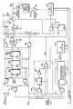
- FIG. 2 A block diagram of a circuit in accordance with the present invention is shown in Fig. 2.
- the circuit 40 is shown comprising a stimulation timing circuit 42 which contains the normal pacemaker timing and logic circuitry.
- the circuit 40 is coupled to control the actuation of a switch S1 upon the occurrence of a stimulation signal STIM.
- the source of the pacing output at terminal 46 is a capacitor C1 which is coupled to be charged by a charging circuit 44 and which delivers the pacing pulse to the output 46 through a series capacitor C4 when the switch S1 is closed.
- Resistor R2 is provided to complete the circuit to capacitor C4 when switch S1 is open.
- the stimulating impedance discriminator 54 maintains a moving average of lead impedance measurements according to Equation (1) and compares each new measurement with that average. If the measurement of lead impedance differs from the moving average by a predetermined value, an associated counter 56 is incremented to count the event as the occurrence of an error.
- a polarity detector 55 is shown connected to the stimulating impedance discriminator 54 to provide an indication for the readout logic stage 70 of the direction of change for any differences in measurement of lead impedance which are detected by the stimulating impedance discriminator 54.
- the polarity detector 55 provides an output indication of whether detected changes in lead impedance measurements involve an increase or decrease in impedance. This corresponds to an indication that lead degradation is in the direction of an open circuit (corresponding to measured increases in lead impedance) or in the direction of a short circuit (corresponding to a measured reduction in lead impedance).
- a sensing detector 60 is coupled to the terminal 46 to respond to sensed heart activity.
- the output of the sensing detector 60 is applied to a sensing impedance discriminator 62 which receives a delayed signal DS from a monostable delay circuit 64 that is triggered by the STIM output of the stimulation timing circuit 42. This serves to prevent indication of high slew rate signals from stimulation output origin.
- the output of the sensing impedance discriminator 62 is applied to a second counter 66.
- the sensing impedance discriminator 62 responds to the slope (slew) of the signal from the sensing detector 60 such that when a rate of change greater than 10 volts per second is detected, the count in the counter 66 is incremented.
- a second polarity detector 63 is shown coupled to the sensing impedance discriminator 62 with an output being directed to the readout logic stage 70, in much the same fashion and for the same purpose as the polarity detector 55 which is connected to the stimulating impedance discriminator 54.
- the detector 63 provides an output indication of increasing impedance where the slope of the signal from the sensing detector 60 is positive and an output indication of decreasing impedance where the slope of that signal is negative.
- additional diagnostic information is provided at the readout logic stage 70 in response to polarity detectors 55, 63 over and above the mere indication of a detected change in lead impedance.
- a readout logic stage 70 is coupled to the outputs of both counter stages 56 and 66 to provide an indication of the number of errors detected by the respective portions (stimulating signal and sensing signal) of the lead impedance analyzing circuit 40.
- the inputs designated by the letter C indicate connections from the various stages to a system clock (not shown).
- Fig. 3 represents the circuit 40 of Fig. 2 in more detailed schematic circuit form.
- like elements have been given corresponding designations to those shown in Fig. 2.
- the charging circuit 44 is represented as comprising a switch S2 and a capacitor C2, the latter having a small capacitance by comparison with C1.
- C2 quickly assumes the voltage level of C1 without producing noticeable change therein.
- the circuit of R1 and C3 serves to create a moving average of the voltage level of C1, since C3 has a much greater capacitance than C2.
- Switches S3 and S4 are connected to provide alternating charge and discharge pulses to one input terminal of a first comparator stage 80 which is connected to receive at its other input the moving average of C1 voltage level.
- the output of the comparator 80 is coupled to the first stage 82 of a three-bit shift register 88, having additional stages 84 and 86.
- the outputs of the individual stage 82, 84, 86 are applied to three-terminal NAND gates 90, 92 while the outputs of the first stage 82 are additionally applied to two-input NAND gates 94, 96 which control switches S3 and S4.
- the outputs of the NAND gates 90, 92 are applied to a further NAND gate 98, the output of which is applied to one input of AND gate 100.
- An active output from gate 98 signifies the occurrence of an event corresponding to the detection of three successive errors or anomalous impedance measurements.
- the output of AND gate 100 is coupled to a programmable down counter 102, which in turn is coupled to an up counter 104.
- the programmable down counter 102 is connected to be set to a predetermined value delivered over the data bus 110, the latter being connected to receive the count in the up counter 104.
- the monostable delay circuit 64 of Fig. 2 comprises a flip flop 120 coupled to receive the output of an NOR gate 122 and to provide an output through a buffer amplifier 124 to another NOR gate 126. This serves to provide a delayed signal DS following a stimulation pulse from the stimulation timing circuit 42 of Fig. 2 in phase with a clock signal.
- the sensing portion of the circuit comprises a sense amplifier 130 coupled to receive heart signals for terminal 46 and apply them through a high pass filter 132 to one input of a second comparator stage 134, the other input of which is coupled to a voltage reference Vref.
- the output of comparator stage 134 is applied to a flip flop 136, the output of which is applied, with the stimulation signal STIM, to an AND gate 138 which in turn is coupled to drive an up counter 140.
- the counter 140 is connected to provide data to the data bus 110.
- the delayed DS signal is developed.
- capacitor C2 is connected to capacitor C1 via switch S2, and the same voltage level is developed on both capacitors C1 and C2.
- Alternation of the switch S2 transfers charge samples in bucket and dipper fashion from capacitor C1 to capacitor C3 in the moving average circuit to provide a voltage at one input of the comparator 80.
- the stimulation pulse activates switch S1 to provide a pacing signal at terminal 46 from the capacitor C1.
- a momentary change of lead impedance in the lead connected to output terminal 46 creates a difference of potentials in capacitors C2 and C3 which is sensed by the comparator 80 and applied to the shift register 88 at input stage 82. If three consecutive deviation signals are applied to the shift register 88, gates 90, 92 and 98 are activated to develop a condition at the input to gate 100 signifying an event. This in phase with a clock pulse activates AND gate 100 to decrement the down counter 102. The counter 102 is set to a predetermined count value on receipt of a STIM signal. When the voltage difference between capacitor C2 and capacitor C3 exceeds a certain threshold value, the output of gate 98 is active long enough to develop the output from the programmable down counter 102, thereby incrementing the up counter 104.
- a rapidly changing input signal to the sense amplifier 130 produces a voltage level at the comparator 134 which is higher than Vref.
- the signal form the comparator 134 sets the flip flop 136 if the DS signal is low.
- the next stimulating pulse from the stage 42 (Fig. 2) will increment the second counter 140.
- the two counters 104 and 140 are read via the data bus 110. From the numbers read out of the counters 104 and 140, determinations of system performance, relative to the impedance condition of the pacer leads may be made.
- arrangements in accordance with the present invention monitor a prescribed pacemaker parameter related to the integrity of the implanted leads and keep a count according to the occurrences of a predetermined number of detected anomalies in succession.
- An anomaly is determined to be a deviation from the norm for that parameter by some predetermined amount. What constitutes the norm is determined from the operation of the system over time. Isolated anomalies corresponding to a single occurrence are disregarded, but if the particular anomaly persists over three heart beats, the occurrence of the event is recorded in a counter. Thus, at some later tine, such as during a routing patient checkup, for example, the contents of the counter may be noted so that a decision may be made with respect to whether or not the possible problem corresponding to the noted events needs to be corrected.
- the preferred embodiment of the invention advantageously provides two distinct related systems for noting anomalies with respect to the testing of lead impedance.
- One system is based upon measurement of output energy delivered to the stimulation circuit during pacing; the other system involves the measurement of lead impedance from the monitoring of sensed heart signals.
- An analysis of the count readouts in the independent counters of both systems may further enhance the process of determining the particular lead problem which is indicated, particularly from a correlation of the separate count readouts as in the case of a pacemaker system which uses the same lead for sensing and pacing.
Landscapes
- Health & Medical Sciences (AREA)
- Heart & Thoracic Surgery (AREA)
- Life Sciences & Earth Sciences (AREA)
- Radiology & Medical Imaging (AREA)
- Cardiology (AREA)
- Engineering & Computer Science (AREA)
- Biomedical Technology (AREA)
- Nuclear Medicine, Radiotherapy & Molecular Imaging (AREA)
- Biophysics (AREA)
- Animal Behavior & Ethology (AREA)
- General Health & Medical Sciences (AREA)
- Public Health (AREA)
- Veterinary Medicine (AREA)
- Physics & Mathematics (AREA)
- General Physics & Mathematics (AREA)
- Electrotherapy Devices (AREA)
Claims (22)
- Ein Apparat (40) zur Bestimmung der Leitungsimpedanz für eine implantierbaren Stimulierungsvorrichttung (10) mit:
Mitteln (54,62) zur Durchführung des Messens der Leitungsimpedanz während des Betriebs der Vorrichtung (10), wobei diese Mittel (54,62) Mittel (50) zum Bestimmen der während eines Stimulierungsimpulses an die Stimulierungselektrode (46) abgegebenen Energie enthalten;
Mitteln (80,134) zum Vergleichen dieser Impedanzmessungen mit mindestens einem vorgewählten Referenzwert; und
Mitteln (56), die auf die Detektion einer Meßabweichung, die von dem vorgewählten Referenzwert um einen vorbestimmten Betrag abweicht, ansprechen, um das Auftreten einer Änderung der Elektrodenimpedanz anzuzeigen, dadurch gekennzeichnet, daß der vorgewählte Referenzwert durch Mittel (R1,C3) zur Entwicklung eines beweglichen Mittelwertes der Impedanzmessungen gebildet wird. - Apparat nach Anspruch 1 mit einem Zähler (56) zum Zählen der Ereignisse, die zu den Meßabweichungen korrespondieren, für eine nachfolgende Analyse als Indikation einer möglicherweise defekten Elektrode und Mitteln (88), um den Zähler (56) unter vorbestimmten zu den Meßabweichungen in Beziehung stehenden Bedingungen fortzuschreiben.
- Apparat nach Anspruch 2, bei dem die Mittel (88) zum Fortschreiben des Zählers (56) Mittel (88) enthalten, die nur beim Vorliegen einer vorbestimmten Anzahl von aufeinanderfolgender Meßabweichungen ein Zählerfortschreibsignals bilden.
- Apparat nach Anspruch 3, bei dem die zuletztgenannten Mittel (88) ein Dreibit Schieberegister (88) aufweisen, das nur beim Vorliegen vor drei aufeinanderfolgenden Meßabweichungen ein Zählerfortschreibsignal bildet.
- Apparat nach einem der vorangehenden Ansprüche, der zusätzlich Mittel (55) zum Detektieren der Richtung der Änderung der Impedanz relativ zu dem Referenzwert enthält, um eine Indikation dieser detektierten Richtung der Änderung der Impedanz zu schaffen.
- Apparat nach irgendeinem der vorangehenden Ansprüche, wobei die Mittel (50) zum Bestimmen der Energie Abtastmittel (50) zum Abtasten des Energieniveaus der Quelle der Stimulierungsimpulse vor und nach der Abgabe eines Stimulierungsimpulses enthalten.
- Apparat nach Anspruch 6, wobei die Abtastspannungen der Abtastmittel (50) dazu benutzt werden, eine Messung der Impedanz in Übereinstimmung mit den folgenden Gleichungen zu schaffen:

wobeiR die Elektrodenimpedanz repräsentiert,Tp die Stimlierungsimpulsdauer ist,C1 die Speicherkondensatorquelle für den Stimulierungsimpuls ist,Vo die Quellenspannung ist unddV die Spannungsdifferenz zwischen zwei Abtastspannungen ist, die vor und nach der Abgabe eines Stimulierungsimpulses erfaßt wurden. - Apparat nach einem der vorangehenden Ansprüche, wobei die Mittel (54,62) zur Durchführung des Messens der Elektrodenimpedanz Mittel (62) zur Messung der Elektrodenimpedanz aus detektierten Herzsignalen enthält.
- Apparat nach Anspruch 8, wobei die Mittel (54,62) zur Durchführung des Messens der Elektrodenimpedanz Mittel (62) zum Bilden von Signalen aufweisen, die zu der Steigung der detektierten Herzsignale korrespondieren.
- Apparat nach Anspruch 9 zusätzlich mit einem Zähler (66) zum Zählen von Ereignissen, die zu Abweichungen der Herzsignalimpedanzmessungen korrespondieren, zur nachfolgenden Analyse als Indikation einer möglicherweise defekten Elektrode und Mitteln (62) zum Fortschreiben des Zählers (66) unter vorbestimmten mit den Meßabweichungen in Beziehung stehenden Bedingungen.
- Apparat nach Anspruch 10, wobei die Vergleichsmittel (80,134) einen Komparator (134) zum Vergleichen des Steigungssignals mit einem ausgewählten Spannungsreferenzwert (Vref) aufweisen und den Zähler (66) nur fortschreiben, wenn das Steigungssignal den Spannungsreferenzwert (Vref) überschreitet.
- Apparat nach Anspruch 11 weiterhin mit Mitteln (63) zur Indikation der Polarität des Steigungssignals, um die Richtung der Impedanzänderung zu zeigen.
- Verfahren zum Entdecken einer defekten Elektrode einer implantierbaren Stimulierungsvorrichtung mit den Schritten:
Durchführen von Elektrodenimpedanzmessungen während des Betriebs der Vorrichtung, wobei die an die Stimulierungselektrode abgegebene Energie während des Stimulierungsimpulses bestimmt wird;
Vergleichen dieser Impedanzmessungen mit mindestens einem vorgewählten Referenzwert; und
Wahrnehmen des Auftretens von Meßabweichungen, die von dem vorgewählten Referenzwert um einen vorbestimmten Betrag abweichen, gekennzeichnet durch
den Schritt der Entwicklung eines beweglichen Mittelwertes der Impedanzmessungen als vorgewählten Referenzwert für den Vergleich mit individuellen Impedanzmessungen. - Verfahren nach Anspruch 13 weiterhin mit dem Schritt, einen Zählwert mit vorbestimmter Zahl von aufeinanderfolgenden Meßabweichungen für die nachfolgende Analyse als eine Indikation einer defekten Elektrode zu bilden; wobei diese vorbestimmte Zahl unter vorbestimmten Konditionen in Beziehung zu des Meßabweichungen definiert ist.
- Verfahren nach Anspruch 14, wobei die vorbestimmte Zahl drei ist.
- Verfahren nach einem der vorangehenden Verfahrensansprüche weiterhin mit den Schritten, die Polarität der Meßabweichungen relativ zu dem Referenzwert zu detektieren und eine Indikation der Impedanzänderung zu schaffen.
- Verfahren nach einem der vorangehenden Verfahrensansprüche, wobei der Schritt der Bestimmung der an die Stimulierungselektrode abgegebenen Energie das Abtasten der Quelle der Stimulierung vor und nach der Abgabe eines Stimulierungsimpulses umfaßt.
- Verfahren nach Anspruch 17, wobei Proben des Abtastschrittes dazu verwendet werden, eine Messung der Impedanz in Übereinstimmung mit der folgenden Gleichung zu schaffen:

wobeiR die Elektrodenimpedanz repräsentiert,Tp die Stimulierungsimpulsdauer ist,C1 die Speicherkondensatorquelle für den Stimulierungsimpuls ist,Vo die Quellenspannung ist unddV die Spannungsdifferenz zwischen zwei Abtastspannungen ist, die vor und nach der Abgabe eines Stimulierungsimpulses erfaßt wurden. - Verfahren nach einem der vorangehenden Verfahrensansprüche, wobei der Schritt der Durchführung von Elektrodenimpedanzmessungen das Messen der Elektrodenimpedanz aus detektierten Herzsignalen umfaßt.
- Verfahren nach Anspruch 19, wobei der Schritt der Durchführung von Elektrodenimpedanzmessungen zusätzlich das Entwickeln von Signalen umfaßt, die mit der Steigung der detektierten Herzsignalwellenform korrespondieren.
- Verfahren nach Anspruch 20, wobei der Vergleichsschritt das Vergleichen des Steigungssignals mit einem ausgewählten Spannungsreferenzwert und das Zählen der Meßabweichungen nur, wenn das Steigungssignal den Spannungsreferenzwert überschreitet, enthält.
- Verfahren nach Anspruch 19,20 oder 21 zusätzlich mit dem Schritt, die Polarität des Steigungssignals anzuzeigen, um die Richtung der Impedanzänderung darzustellen.
Applications Claiming Priority (2)
| Application Number | Priority Date | Filing Date | Title |
|---|---|---|---|
| US183191 | 1988-04-19 | ||
| US07/183,191 US4899750A (en) | 1988-04-19 | 1988-04-19 | Lead impedance scanning system for pacemakers |
Publications (3)
| Publication Number | Publication Date |
|---|---|
| EP0338364A2 EP0338364A2 (de) | 1989-10-25 |
| EP0338364A3 EP0338364A3 (en) | 1990-08-29 |
| EP0338364B1 true EP0338364B1 (de) | 1994-07-27 |
Family
ID=22671826
Family Applications (1)
| Application Number | Title | Priority Date | Filing Date |
|---|---|---|---|
| EP89106279A Expired - Lifetime EP0338364B1 (de) | 1988-04-19 | 1989-04-10 | System zur Bestimmung der Leitungsimpedanz für Herzschrittmacher |
Country Status (5)
| Country | Link |
|---|---|
| US (1) | US4899750A (de) |
| EP (1) | EP0338364B1 (de) |
| JP (1) | JPH01313065A (de) |
| AU (1) | AU604456B2 (de) |
| DE (1) | DE68916998T2 (de) |
Cited By (4)
| Publication number | Priority date | Publication date | Assignee | Title |
|---|---|---|---|---|
| US7031773B1 (en) | 2003-01-10 | 2006-04-18 | Pacesetter, Inc. | Implantable cardiac stimulation system providing autocapture and lead impedance assessment and method |
| US7308310B1 (en) | 2005-01-26 | 2007-12-11 | Pacesetter, Inc. | Implantable cardiac stimulation device providing bipolar autocapture and lead impedance assessment and method |
| US7574259B1 (en) | 2004-11-12 | 2009-08-11 | Pacesetter, Inc. | Capture threshold and lead condition analysis |
| US9687651B2 (en) | 2013-10-09 | 2017-06-27 | Advanced Bionics Ag | Systems and methods for measuring electrode impedance during a normal operation of a cochlear implant system |
Families Citing this family (136)
| Publication number | Priority date | Publication date | Assignee | Title |
|---|---|---|---|---|
| US5137021A (en) * | 1990-11-29 | 1992-08-11 | Medtronic, Inc. | Lead current measurement circuit |
| US5174286A (en) * | 1990-12-07 | 1992-12-29 | Raul Chirife | Sensor for right ventricular and thoracic volumes using the trailing edge value of a generated pulse |
| US5197479A (en) * | 1991-05-13 | 1993-03-30 | Mortara Instrument | Automatic electrode channel impedance measurement system for egg monitor |
| AU665543B2 (en) * | 1991-06-28 | 1996-01-11 | Liquip Sales Pty Limited | A system/apparatus for indicating electrical continuity of fluid carrying components |
| US5201865A (en) * | 1991-10-28 | 1993-04-13 | Medtronic, Inc. | Medical lead impedance measurement system |
| US5224475A (en) * | 1991-11-20 | 1993-07-06 | Medtronic, Inc. | Method and apparatus for termination of ventricular tachycardia and ventricular fibrillation |
| US6240307B1 (en) | 1993-09-23 | 2001-05-29 | Endocardial Solutions, Inc. | Endocardial mapping system |
| DE69315354T2 (de) * | 1992-09-23 | 1998-03-19 | Endocardial Solutions Inc | Endokard-mapping system |
| US7189208B1 (en) | 1992-09-23 | 2007-03-13 | Endocardial Solutions, Inc. | Method for measuring heart electrophysiology |
| US7930012B2 (en) * | 1992-09-23 | 2011-04-19 | St. Jude Medical, Atrial Fibrillation Division, Inc. | Chamber location method |
| US5297549A (en) * | 1992-09-23 | 1994-03-29 | Endocardial Therapeutics, Inc. | Endocardial mapping system |
| SE9300283D0 (sv) * | 1993-01-29 | 1993-01-29 | Siemens Elema Ab | Foerfarande och anordning foer elektrodoevervakning vid elektriska hjaertstimulatorer |
| US5350401A (en) * | 1993-03-26 | 1994-09-27 | Siemens Pacesetter, Inc. | Implantable cardioverter/defibrillator device having means for determining and treating low amplitude ventricular fibrillation and method thereof |
| US5738096A (en) * | 1993-07-20 | 1998-04-14 | Biosense, Inc. | Cardiac electromechanics |
| US5391199A (en) * | 1993-07-20 | 1995-02-21 | Biosense, Inc. | Apparatus and method for treating cardiac arrhythmias |
| US5431692A (en) * | 1993-08-02 | 1995-07-11 | Telectronics Pacing Systems, Inc. | Method and apparatus for testing compatibility of lead polarity and polarity programming of a cardiac stimulator |
| US5454377A (en) * | 1993-10-08 | 1995-10-03 | The Ohio State University | Method for measuring the myocardial electrical impedance spectrum |
| US5713367A (en) * | 1994-01-26 | 1998-02-03 | Cambridge Heart, Inc. | Measuring and assessing cardiac electrical stability |
| US5507786A (en) * | 1994-04-14 | 1996-04-16 | Pacesetter, Inc. | System and method for measuring and storing parametric data pertaining to operating characteristics of an implantable medical device |
| US5713933A (en) * | 1994-11-30 | 1998-02-03 | Medtronic, Inc. | Method and apparatus for automatic pacing threshold determination |
| US5534018A (en) * | 1994-11-30 | 1996-07-09 | Medtronic, Inc. | Automatic lead recognition for implantable medical device |
| US5549646A (en) * | 1994-12-06 | 1996-08-27 | Pacesetter, Inc. | Periodic electrical lead intergrity testing system and method for implantable cardiac stimulating devices |
| US5795298A (en) * | 1995-03-28 | 1998-08-18 | Sonometrics Corporation | System for sharing electrocardiogram electrodes and transducers |
| US5817022A (en) * | 1995-03-28 | 1998-10-06 | Sonometrics Corporation | System for displaying a 2-D ultrasound image within a 3-D viewing environment |
| US6246898B1 (en) | 1995-03-28 | 2001-06-12 | Sonometrics Corporation | Method for carrying out a medical procedure using a three-dimensional tracking and imaging system |
| US5830144A (en) * | 1995-03-28 | 1998-11-03 | Vesely; Ivan | Tracking data sheath |
| US5868673A (en) * | 1995-03-28 | 1999-02-09 | Sonometrics Corporation | System for carrying out surgery, biopsy and ablation of a tumor or other physical anomaly |
| US5797849A (en) * | 1995-03-28 | 1998-08-25 | Sonometrics Corporation | Method for carrying out a medical procedure using a three-dimensional tracking and imaging system |
| US5620474A (en) * | 1995-04-24 | 1997-04-15 | Vitatron Medical, B.V. | System and method for determining indicated pacemaker replacement time based upon battery impedance measurement |
| US5718241A (en) * | 1995-06-07 | 1998-02-17 | Biosense, Inc. | Apparatus and method for treating cardiac arrhythmias with no discrete target |
| US5954665A (en) * | 1995-06-07 | 1999-09-21 | Biosense, Inc. | Cardiac ablation catheter using correlation measure |
| DE69628906T2 (de) * | 1995-09-29 | 2004-05-19 | Medtronic, Inc., Minneapolis | Anpassungsfähige suche der av verzögerung |
| US5776168A (en) * | 1996-04-03 | 1998-07-07 | Medtronic, Inc. | EGM recording system for implantable medical device |
| SE9602440D0 (sv) * | 1996-06-20 | 1996-06-20 | Pacesetter Ab | Medical apparatus |
| US5837900A (en) * | 1996-06-21 | 1998-11-17 | Medtronic Inc | System and method for detecting metal ion oxidation in pacing lead |
| US5741311A (en) * | 1996-06-27 | 1998-04-21 | Medtronic, Inc. | Implantable medical device system with method for determining lead condition |
| US5722997A (en) * | 1996-09-17 | 1998-03-03 | Sulzer Intermedics Inc. | Method and apparatus for cardiac impedance sensing |
| US5755742A (en) * | 1996-11-05 | 1998-05-26 | Medtronic, Inc. | Cardioversion/defibrillation lead impedance measurement system |
| US6019725A (en) * | 1997-03-07 | 2000-02-01 | Sonometrics Corporation | Three-dimensional tracking and imaging system |
| US5814088A (en) * | 1997-03-26 | 1998-09-29 | Sulzer Intermedics Inc. | Cardiac stimulator with lead failure detector and warning system |
| US6490474B1 (en) | 1997-08-01 | 2002-12-03 | Cardiac Pathways Corporation | System and method for electrode localization using ultrasound |
| US5897577A (en) * | 1997-11-07 | 1999-04-27 | Medtronic, Inc. | Pacing lead impedance monitoring circuit and method |
| US5910156A (en) * | 1997-11-07 | 1999-06-08 | Medtronic Inc. | Non-physiologic sense detection for implantable medical devices |
| US5891179A (en) * | 1997-11-20 | 1999-04-06 | Paceseter, Inc. | Method and apparatus for monitoring and displaying lead impedance in real-time for an implantable medical device |
| US6022322A (en) * | 1998-02-06 | 2000-02-08 | Intermedics Inc. | Non-invasive cardiorespiratory monitor with synchronized bioimpedance sensing |
| US6141585A (en) | 1998-05-08 | 2000-10-31 | Intermedics Inc. | Implantable cardiac stimulator with electrode-tissue interface characterization |
| ATE311927T1 (de) * | 1998-06-03 | 2005-12-15 | Neurocontrol Corp | Perkutanes intramuskuläres stimulationssystem |
| US7806829B2 (en) | 1998-06-30 | 2010-10-05 | St. Jude Medical, Atrial Fibrillation Division, Inc. | System and method for navigating an ultrasound catheter to image a beating heart |
| US7670297B1 (en) | 1998-06-30 | 2010-03-02 | St. Jude Medical, Atrial Fibrillation Division, Inc. | Chamber mapping system |
| US7263397B2 (en) | 1998-06-30 | 2007-08-28 | St. Jude Medical, Atrial Fibrillation Division, Inc. | Method and apparatus for catheter navigation and location and mapping in the heart |
| US6950689B1 (en) | 1998-08-03 | 2005-09-27 | Boston Scientific Scimed, Inc. | Dynamically alterable three-dimensional graphical model of a body region |
| US5944746A (en) * | 1998-10-30 | 1999-08-31 | Pacesetter, Inc. | ICD with continuous regular testing of defibrillation lead status |
| US6317633B1 (en) | 1999-01-19 | 2001-11-13 | Medtronic, Inc. | Implantable lead functional status monitor and method |
| US6721600B2 (en) | 2000-01-19 | 2004-04-13 | Medtronic, Inc. | Implantable lead functional status monitor and method |
| US6370432B1 (en) * | 1999-08-20 | 2002-04-09 | Cardiac Pacemakers, Inc. | Pacemaker passive measurement testing system and method |
| US6445952B1 (en) | 2000-05-18 | 2002-09-03 | Medtronic, Inc. | Apparatus and method for detecting micro-dislodgment of a pacing lead |
| US6687538B1 (en) * | 2000-06-19 | 2004-02-03 | Medtronic, Inc. | Trial neuro stimulator with lead diagnostics |
| WO2002018009A1 (en) | 2000-08-26 | 2002-03-07 | Medtronic, Inc. | Implantable lead functional status monitor and method |
| US6658294B1 (en) | 2001-08-29 | 2003-12-02 | Pacesetter, Inc. | Implantable cardiac device having an impedance monitoring circuit and method |
| FR2831743B1 (fr) * | 2001-10-25 | 2004-01-30 | Cit Alcatel | Systeme de routage is-is tolerant aux fautes et procede correspondant |
| US6695790B2 (en) | 2001-10-26 | 2004-02-24 | Medtronic, Inc. | Method and system for determining kidney failure |
| US20030199938A1 (en) * | 2002-04-22 | 2003-10-23 | Karel Smits | Precise cardiac lead placement based on impedance measurements |
| US7047083B2 (en) * | 2002-09-30 | 2006-05-16 | Medtronic, Inc. | Method and apparatus for identifying lead-related conditions using lead impedance measurements |
| US8010207B2 (en) | 2002-10-31 | 2011-08-30 | Medtronic, Inc. | Implantable medical lead designs |
| US20040088033A1 (en) * | 2002-10-31 | 2004-05-06 | Smits Karel F.A.A. | Implantable medical lead designs |
| US20050261571A1 (en) * | 2004-05-21 | 2005-11-24 | Willis Nathaniel P | 3-D ultrasound navigation during radio-frequency ablation |
| US20060025828A1 (en) * | 2004-07-28 | 2006-02-02 | Armstrong Randolph K | Impedance measurement for an implantable device |
| WO2006119103A2 (en) * | 2005-04-29 | 2006-11-09 | Medtronic, Inc. | Event-based lead impedance monitoring |
| US7515961B2 (en) * | 2005-04-29 | 2009-04-07 | Medtronic, Inc. | Method and apparatus for dynamically monitoring, detecting and diagnosing lead conditions |
| EP1883450B1 (de) * | 2005-04-29 | 2009-12-09 | Medtronic, Inc. | Funktionstest für verteilte leitungskabel |
| US7644714B2 (en) * | 2005-05-27 | 2010-01-12 | Apnex Medical, Inc. | Devices and methods for treating sleep disorders |
| US7567840B2 (en) * | 2005-10-28 | 2009-07-28 | Cyberonics, Inc. | Lead condition assessment for an implantable medical device |
| EP1960040B1 (de) * | 2005-12-01 | 2017-02-08 | Second Sight Medical Products, Inc. | Einsatz einer nervenprothese über impedanz und elektrodenhöhe |
| US7769455B2 (en) * | 2006-01-27 | 2010-08-03 | Cyberonics, Inc. | Power supply monitoring for an implantable device |
| US8180462B2 (en) * | 2006-04-18 | 2012-05-15 | Cyberonics, Inc. | Heat dissipation for a lead assembly |
| US7899535B2 (en) * | 2006-06-16 | 2011-03-01 | Cardiac Pacemakers, Inc. | Automatic electrode integrity management systems and methods |
| US8478420B2 (en) * | 2006-07-12 | 2013-07-02 | Cyberonics, Inc. | Implantable medical device charge balance assessment |
| US20080027524A1 (en) * | 2006-07-26 | 2008-01-31 | Maschino Steven E | Multi-electrode assembly for an implantable medical device |
| US9744354B2 (en) | 2008-12-31 | 2017-08-29 | Cyberonics, Inc. | Obstructive sleep apnea treatment devices, systems and methods |
| EP2116274B1 (de) | 2006-10-13 | 2012-07-11 | Apnex Medical, Inc. | Vorrichtung zur Behandlung von obstruktiver Schlaf-Apnea |
| US8855771B2 (en) | 2011-01-28 | 2014-10-07 | Cyberonics, Inc. | Screening devices and methods for obstructive sleep apnea therapy |
| US9913982B2 (en) | 2011-01-28 | 2018-03-13 | Cyberonics, Inc. | Obstructive sleep apnea treatment devices, systems and methods |
| US9186511B2 (en) | 2006-10-13 | 2015-11-17 | Cyberonics, Inc. | Obstructive sleep apnea treatment devices, systems and methods |
| US9205262B2 (en) | 2011-05-12 | 2015-12-08 | Cyberonics, Inc. | Devices and methods for sleep apnea treatment |
| US7930028B2 (en) * | 2006-10-20 | 2011-04-19 | Biotronik Crm Patent Ag | Implantable cardiac device with a shock lead |
| US7974707B2 (en) * | 2007-01-26 | 2011-07-05 | Cyberonics, Inc. | Electrode assembly with fibers for a medical device |
| US8868203B2 (en) * | 2007-10-26 | 2014-10-21 | Cyberonics, Inc. | Dynamic lead condition detection for an implantable medical device |
| US8942798B2 (en) * | 2007-10-26 | 2015-01-27 | Cyberonics, Inc. | Alternative operation mode for an implantable medical device based upon lead condition |
| US20090299421A1 (en) * | 2008-06-02 | 2009-12-03 | Medtronic, Inc. | Evaluation of implantable medical device sensing integrity based on evoked signals |
| WO2009148428A1 (en) * | 2008-06-02 | 2009-12-10 | Medtronic, Inc. | Electrode lead integrity reports |
| WO2009148425A1 (en) * | 2008-06-02 | 2009-12-10 | Medtronic, Inc. | Impedance variability analysis to identify lead-related conditions |
| US8200322B2 (en) * | 2008-06-02 | 2012-06-12 | Medtronic, Inc. | Electrogram storage for suspected non-physiological episodes |
| US8126553B2 (en) * | 2008-06-02 | 2012-02-28 | Medtronic, Inc. | Sensing integrity determination based on cardiovascular pressure |
| US7974690B2 (en) * | 2008-06-30 | 2011-07-05 | Medtronic, Inc. | Lead integrity testing during suspected tachyarrhythmias |
| US9522277B2 (en) | 2008-07-28 | 2016-12-20 | Medtronic, Inc. | Lead integrity testing triggered by sensed signal saturation |
| US7953488B2 (en) * | 2008-07-31 | 2011-05-31 | Medtronic, Inc. | Pre-qualification of an alternate sensing configuration |
| US8078277B2 (en) | 2008-10-29 | 2011-12-13 | Medtronic, Inc. | Identification and remediation of oversensed cardiac events using far-field electrograms |
| US10118042B2 (en) | 2008-10-31 | 2018-11-06 | Medtronic, Inc. | Lead integrity testing triggered by sensed asystole |
| US8311639B2 (en) * | 2009-07-08 | 2012-11-13 | Nevro Corporation | Systems and methods for adjusting electrical therapy based on impedance changes |
| EP3431137A1 (de) | 2009-02-10 | 2019-01-23 | Nevro Corporation | Systeme zur verabreichung einer neuralen therapie in korrelation zum patientenstatus |
| US8406892B2 (en) * | 2009-06-15 | 2013-03-26 | Kallis Technical Services | Method and apparatus for detecting imminent structural failure of an electrical lead in an implanted cardiac therapy medical device |
| US8498710B2 (en) | 2009-07-28 | 2013-07-30 | Nevro Corporation | Linked area parameter adjustment for spinal cord stimulation and associated systems and methods |
| US20110098765A1 (en) * | 2009-10-27 | 2011-04-28 | Medtronic, Inc. | Detecting lead related condition during delivery of therapeutic electrical signals |
| US8396543B2 (en) * | 2010-01-28 | 2013-03-12 | Medtronic, Inc. | Storage of data for evaluation of lead integrity |
| US8478428B2 (en) | 2010-04-23 | 2013-07-02 | Cyberonics, Inc. | Helical electrode for nerve stimulation |
| US8874229B2 (en) | 2010-04-28 | 2014-10-28 | Cyberonics, Inc. | Delivering scheduled and unscheduled therapy without detriment to battery life or accuracy of longevity predictions |
| US8543206B2 (en) | 2010-06-25 | 2013-09-24 | Pacesetter, Inc. | Early detection of lead failure using an impedance histogram |
| US9539428B2 (en) | 2011-01-27 | 2017-01-10 | Medtronic, Inc. | Isolating lead conductor for fault detection |
| US8463384B2 (en) | 2011-01-27 | 2013-06-11 | Medtronic, Inc. | Isolated lead conductor measurements for fault detection |
| US8577459B2 (en) | 2011-01-28 | 2013-11-05 | Cyberonics, Inc. | System and method for estimating battery capacity |
| US8761884B2 (en) | 2011-04-14 | 2014-06-24 | Cyberonics, Inc. | Device longevity prediction for a device having variable energy consumption |
| US8761885B2 (en) | 2011-04-29 | 2014-06-24 | Cyberonics, Inc. | Battery life estimation based on voltage depletion rate |
| US8855765B2 (en) | 2011-06-09 | 2014-10-07 | Medtronic, Inc. | Fault tolerant methods and architectures for embedded intelligence in medical leads |
| US8798751B2 (en) | 2011-06-09 | 2014-08-05 | Medtronic, Inc. | Method and apparatus to manage lead-related conditions for fault tolerance enhancements |
| US8577457B2 (en) | 2011-07-07 | 2013-11-05 | Medtronics, Inc. | Isolating lead body for fault detection |
| US8774909B2 (en) | 2011-09-26 | 2014-07-08 | Medtronic, Inc. | Episode classifier algorithm |
| US8437840B2 (en) | 2011-09-26 | 2013-05-07 | Medtronic, Inc. | Episode classifier algorithm |
| US8744560B2 (en) | 2011-09-30 | 2014-06-03 | Medtronic, Inc. | Electrogram summary |
| US9668668B2 (en) | 2011-09-30 | 2017-06-06 | Medtronic, Inc. | Electrogram summary |
| US8521281B2 (en) | 2011-10-14 | 2013-08-27 | Medtronic, Inc. | Electrogram classification algorithm |
| US8886296B2 (en) | 2011-10-14 | 2014-11-11 | Medtronic, Inc. | T-wave oversensing |
| US9232898B2 (en) | 2011-10-27 | 2016-01-12 | Medtronic, Inc. | Method and apparatus to manage lead-related conditions for fault tolerance enhancements |
| US9814884B2 (en) | 2011-11-04 | 2017-11-14 | Nevro Corp. | Systems and methods for detecting faults and/or adjusting electrical therapy based on impedance changes |
| US9956417B2 (en) | 2012-05-08 | 2018-05-01 | Medtronic, Inc. | Identifying lead insulation breaches and externalization of lead conductors |
| US9895538B1 (en) | 2013-01-22 | 2018-02-20 | Nevro Corp. | Systems and methods for deploying patient therapy devices |
| US9731133B1 (en) | 2013-01-22 | 2017-08-15 | Nevro Corp. | Systems and methods for systematically testing a plurality of therapy programs in patient therapy devices |
| US9295840B1 (en) | 2013-01-22 | 2016-03-29 | Nevro Corporation | Systems and methods for automatically programming patient therapy devices |
| US9764139B2 (en) | 2014-01-24 | 2017-09-19 | Medtronic, Inc. | Pre-implant detection |
| EP3104768B1 (de) | 2014-02-11 | 2023-07-26 | Cyberonics, Inc. | Systeme zur erkennung und behandlung obstruktiver schlafapnoe |
| WO2015123483A1 (en) | 2014-02-13 | 2015-08-20 | Medtronic, Inc. | Lead monitoring frequency based on lead and patient characteristics |
| US9517344B1 (en) | 2015-03-13 | 2016-12-13 | Nevro Corporation | Systems and methods for selecting low-power, effective signal delivery parameters for an implanted pulse generator |
| US10300277B1 (en) | 2015-12-14 | 2019-05-28 | Nevro Corp. | Variable amplitude signals for neurological therapy, and associated systems and methods |
| US11235165B2 (en) * | 2019-02-04 | 2022-02-01 | Pacesetter, Inc. | Lead impedance monitoring for an implantable medical device |
| CN110193142A (zh) * | 2019-05-24 | 2019-09-03 | 深圳市先健心康医疗电子有限公司 | 起搏导线脱落检测方法及临时心脏起搏器 |
| EP4714490A3 (de) * | 2020-01-05 | 2026-04-01 | Impulse Dynamics NV | Prüfung von elektrodenzuständen in einem implantierten herzschrittmacher |
| CN116407758A (zh) * | 2021-12-29 | 2023-07-11 | 精能医学股份有限公司 | 阻抗监控方法、电刺激系统和电脑可读存储媒体 |
Family Cites Families (13)
| Publication number | Priority date | Publication date | Assignee | Title |
|---|---|---|---|---|
| US4088139A (en) * | 1976-03-08 | 1978-05-09 | Medalert Corporation | Automatic detection and registration of failure condition in a cardiac pacer monitoring system |
| US4140131A (en) * | 1976-11-03 | 1979-02-20 | Medtronic, Inc. | Body tissue stimulation apparatus with warning device |
| IT1118131B (it) * | 1978-07-20 | 1986-02-24 | Medtronic Inc | Perfezionamento nei pacemaker cardiaci multi-modo adattabili impiantabili |
| US4459995A (en) * | 1979-03-08 | 1984-07-17 | Lafayette R. Hubbard | Indicating device for use in a device for measuring and indicating changes in resistance of a living body |
| US4380237A (en) * | 1979-12-03 | 1983-04-19 | Massachusetts General Hospital | Apparatus for making cardiac output conductivity measurements |
| US4527567A (en) * | 1980-04-01 | 1985-07-09 | Yeda Research & Development Company, Ltd. | Method and apparatus for automatically evaluating the quality of the performance of a cardiac pacing system |
| US4476869A (en) * | 1980-06-05 | 1984-10-16 | Intermedics, Inc. | Pacer analyzer |
| US4630615A (en) * | 1984-05-21 | 1986-12-23 | Cordis Corporation | Apparatus for measuring impedance |
| US4606350A (en) * | 1984-11-28 | 1986-08-19 | Telectronics N.V. | Pacemaker battery impedance test circuit and method of operation |
| FR2585557B1 (fr) * | 1985-08-02 | 1987-11-06 | Centre Nat Rech Scient | Dispositif de mesure de caracteristiques electriques de tissus vivants, et en particulier de la temperature pour hyperthermie capacitive ou radiative |
| US4674518A (en) * | 1985-09-06 | 1987-06-23 | Cardiac Pacemakers, Inc. | Method and apparatus for measuring ventricular volume |
| US4697591A (en) * | 1986-06-16 | 1987-10-06 | Siemens Aktiengesellschaft | Cardiac pacer for pacing a human heart and pacing method |
| AU625593B2 (en) * | 1987-06-30 | 1992-07-16 | Ventracor Limited | Combined pacemaker parameter and vital sign monitor |
-
1988
- 1988-04-19 US US07/183,191 patent/US4899750A/en not_active Expired - Lifetime
-
1989
- 1989-04-10 DE DE68916998T patent/DE68916998T2/de not_active Expired - Fee Related
- 1989-04-10 EP EP89106279A patent/EP0338364B1/de not_active Expired - Lifetime
- 1989-04-14 JP JP1095074A patent/JPH01313065A/ja active Pending
- 1989-04-18 AU AU33142/89A patent/AU604456B2/en not_active Ceased
Cited By (8)
| Publication number | Priority date | Publication date | Assignee | Title |
|---|---|---|---|---|
| US7031773B1 (en) | 2003-01-10 | 2006-04-18 | Pacesetter, Inc. | Implantable cardiac stimulation system providing autocapture and lead impedance assessment and method |
| US7574259B1 (en) | 2004-11-12 | 2009-08-11 | Pacesetter, Inc. | Capture threshold and lead condition analysis |
| US8498706B2 (en) | 2004-11-12 | 2013-07-30 | Pacesetter, Inc. | Capture threshold and lead condition analysis |
| US9008774B2 (en) | 2004-11-12 | 2015-04-14 | Pacesetter, Inc. | Capture threshold and lead condition analysis |
| US9238136B2 (en) | 2004-11-12 | 2016-01-19 | Pacesetter, Inc. | Capture threshold and lead condition analysis |
| US9511221B2 (en) | 2004-11-12 | 2016-12-06 | Pacesetter, Inc. | Capture threshold and lead condition analysis |
| US7308310B1 (en) | 2005-01-26 | 2007-12-11 | Pacesetter, Inc. | Implantable cardiac stimulation device providing bipolar autocapture and lead impedance assessment and method |
| US9687651B2 (en) | 2013-10-09 | 2017-06-27 | Advanced Bionics Ag | Systems and methods for measuring electrode impedance during a normal operation of a cochlear implant system |
Also Published As
| Publication number | Publication date |
|---|---|
| EP0338364A2 (de) | 1989-10-25 |
| AU3314289A (en) | 1989-10-26 |
| JPH01313065A (ja) | 1989-12-18 |
| EP0338364A3 (en) | 1990-08-29 |
| AU604456B2 (en) | 1990-12-13 |
| US4899750A (en) | 1990-02-13 |
| DE68916998D1 (de) | 1994-09-01 |
| DE68916998T2 (de) | 1995-03-23 |
Similar Documents
| Publication | Publication Date | Title |
|---|---|---|
| EP0338364A2 (de) | System zur Bestimmung der Leitungsimpedanz für Herzschrittmacher | |
| US5201865A (en) | Medical lead impedance measurement system | |
| US5003975A (en) | Automatic electrode configuration of an implantable pacemaker | |
| US5741311A (en) | Implantable medical device system with method for determining lead condition | |
| US5476486A (en) | Automatic atrial pacing pulse threshold determination utilizing an external programmer and a V-sense electrode | |
| US7047083B2 (en) | Method and apparatus for identifying lead-related conditions using lead impedance measurements | |
| US5391192A (en) | Automatic ventricular pacing pulse threshold determination utilizing an external programmer and a surface electrocardiogram | |
| EP0944413B1 (de) | Leitungsimpedanzmessungssystem für kardiovertier/defibrillator | |
| US5458623A (en) | Automatic atrial pacing threshold determination utilizing an external programmer and a surface electrogram | |
| US4827934A (en) | Sensing margin detectors for implantable electromedical devices | |
| US7031773B1 (en) | Implantable cardiac stimulation system providing autocapture and lead impedance assessment and method | |
| US10118042B2 (en) | Lead integrity testing triggered by sensed asystole | |
| EP0338363B1 (de) | Programmierung der Konfiguration eines implantierbaren Schrittmachers | |
| US6317633B1 (en) | Implantable lead functional status monitor and method | |
| EP1525028B1 (de) | Vorrichtung zur messung der impedanz von schockleitungen | |
| US5453698A (en) | Method and system for testing an implantable defibrillator output stage and high voltage lead integrity | |
| US4505276A (en) | Device for detecting retrograde conduction | |
| US6104954A (en) | High frequency lead testing apparatus in an implantable defibrillator | |
| EP0786268A1 (de) | Herzschrittmacher mit Bestätigung des atrialen Einfanges | |
| US7400924B2 (en) | System and method for capture management | |
| Strathmore et al. | Noninvasive Monitoring and Testing of Pacemaker Function. | |
| Frick | Efficiency of a pacemaker clinic to prevent sudden pacing failures | |
| WO1992019319A1 (en) | Apparatus and method for an implanted cardiac pacemaker with multiuse electrode with potential restoration | |
| Rydén et al. | FUNCTIONAL CHECKING OF IMPLANTED CARDIAC PACEMAKERS: Methods, Values Indicative of Impending Pacemaker Failure, and Results of Testing of Fixed Rate, Ventricular Synchronous and A trial Synchronous Pacemakers | |
| Adams | Patient followup systems |
Legal Events
| Date | Code | Title | Description |
|---|---|---|---|
| PUAI | Public reference made under article 153(3) epc to a published international application that has entered the european phase |
Free format text: ORIGINAL CODE: 0009012 |
|
| AK | Designated contracting states |
Kind code of ref document: A2 Designated state(s): DE FR GB IT NL SE |
|
| PUAL | Search report despatched |
Free format text: ORIGINAL CODE: 0009013 |
|
| AK | Designated contracting states |
Kind code of ref document: A3 Designated state(s): DE FR GB IT NL SE |
|
| 17P | Request for examination filed |
Effective date: 19901220 |
|
| 17Q | First examination report despatched |
Effective date: 19930719 |
|
| GRAA | (expected) grant |
Free format text: ORIGINAL CODE: 0009210 |
|
| AK | Designated contracting states |
Kind code of ref document: B1 Designated state(s): DE FR GB IT NL SE |
|
| REF | Corresponds to: |
Ref document number: 68916998 Country of ref document: DE Date of ref document: 19940901 |
|
| ITF | It: translation for a ep patent filed | ||
| PG25 | Lapsed in a contracting state [announced via postgrant information from national office to epo] |
Ref country code: SE Effective date: 19941027 |
|
| ET | Fr: translation filed | ||
| ITPR | It: changes in ownership of a european patent |
Owner name: CESSIONE;PACESETTER AB |
|
| REG | Reference to a national code |
Ref country code: GB Ref legal event code: 732E |
|
| REG | Reference to a national code |
Ref country code: FR Ref legal event code: TP |
|
| PLBI | Opposition filed |
Free format text: ORIGINAL CODE: 0009260 |
|
| 26 | Opposition filed |
Opponent name: BIOTRONIK MESS- UND THERAPIEGERAETE GMBH & CO ING Effective date: 19950427 |
|
| NLS | Nl: assignments of ep-patents |
Owner name: PACESETTER AB |
|
| NLR1 | Nl: opposition has been filed with the epo |
Opponent name: BIOTRONIK MESS- UND THERAPIEGERAETE GMBH & CO INGE |
|
| RAP2 | Party data changed (patent owner data changed or rights of a patent transferred) |
Owner name: PACESETTER AB |
|
| NLT2 | Nl: modifications (of names), taken from the european patent patent bulletin |
Owner name: PACESETTER AB |
|
| PLBF | Reply of patent proprietor to notice(s) of opposition |
Free format text: ORIGINAL CODE: EPIDOS OBSO |
|
| PLBO | Opposition rejected |
Free format text: ORIGINAL CODE: EPIDOS REJO |
|
| APAC | Appeal dossier modified |
Free format text: ORIGINAL CODE: EPIDOS NOAPO |
|
| APAE | Appeal reference modified |
Free format text: ORIGINAL CODE: EPIDOS REFNO |
|
| PGFP | Annual fee paid to national office [announced via postgrant information from national office to epo] |
Ref country code: GB Payment date: 19980320 Year of fee payment: 10 |
|
| RAP2 | Party data changed (patent owner data changed or rights of a patent transferred) |
Owner name: PACESETTER AB |
|
| NLT2 | Nl: modifications (of names), taken from the european patent patent bulletin |
Owner name: PACESETTER AB |
|
| PG25 | Lapsed in a contracting state [announced via postgrant information from national office to epo] |
Ref country code: GB Free format text: LAPSE BECAUSE OF NON-PAYMENT OF DUE FEES Effective date: 19990410 |
|
| GBPC | Gb: european patent ceased through non-payment of renewal fee |
Effective date: 19990410 |
|
| PLBQ | Unpublished change to opponent data |
Free format text: ORIGINAL CODE: EPIDOS OPPO |
|
| PLAB | Opposition data, opponent's data or that of the opponent's representative modified |
Free format text: ORIGINAL CODE: 0009299OPPO |
|
| RAP2 | Party data changed (patent owner data changed or rights of a patent transferred) |
Owner name: ST. JUDE MEDICAL AB |
|
| PLBQ | Unpublished change to opponent data |
Free format text: ORIGINAL CODE: EPIDOS OPPO |
|
| PLAB | Opposition data, opponent's data or that of the opponent's representative modified |
Free format text: ORIGINAL CODE: 0009299OPPO |
|
| R26 | Opposition filed (corrected) |
Opponent name: BIOTRONIK MESS- UND THERAPIEGERAETE GMBH & CO INGE Effective date: 19950427 |
|
| NLT2 | Nl: modifications (of names), taken from the european patent patent bulletin |
Owner name: ST. JUDE MEDICAL AB |
|
| R26 | Opposition filed (corrected) |
Opponent name: BIOTRONIK MESS- UND THERAPIEGERAETE GMBH & CO INGE Effective date: 19950427 |
|
| PGFP | Annual fee paid to national office [announced via postgrant information from national office to epo] |
Ref country code: NL Payment date: 20010322 Year of fee payment: 13 |
|
| NLR1 | Nl: opposition has been filed with the epo |
Opponent name: BIOTRONIK MESS- UND THERAPIEGERAETE GMBH & CO |
|
| APAC | Appeal dossier modified |
Free format text: ORIGINAL CODE: EPIDOS NOAPO |
|
| PLBN | Opposition rejected |
Free format text: ORIGINAL CODE: 0009273 |
|
| STAA | Information on the status of an ep patent application or granted ep patent |
Free format text: STATUS: OPPOSITION REJECTED |
|
| 27O | Opposition rejected |
Effective date: 20010509 |
|
| NLR2 | Nl: decision of opposition | ||
| PG25 | Lapsed in a contracting state [announced via postgrant information from national office to epo] |
Ref country code: NL Free format text: LAPSE BECAUSE OF NON-PAYMENT OF DUE FEES Effective date: 20021101 |
|
| NLV4 | Nl: lapsed or anulled due to non-payment of the annual fee |
Effective date: 20021101 |
|
| APAH | Appeal reference modified |
Free format text: ORIGINAL CODE: EPIDOSCREFNO |
|
| PGFP | Annual fee paid to national office [announced via postgrant information from national office to epo] |
Ref country code: FR Payment date: 20060331 Year of fee payment: 18 |
|
| PGFP | Annual fee paid to national office [announced via postgrant information from national office to epo] |
Ref country code: DE Payment date: 20060424 Year of fee payment: 18 |
|
| PGFP | Annual fee paid to national office [announced via postgrant information from national office to epo] |
Ref country code: IT Payment date: 20060430 Year of fee payment: 18 |
|
| PG25 | Lapsed in a contracting state [announced via postgrant information from national office to epo] |
Ref country code: DE Free format text: LAPSE BECAUSE OF NON-PAYMENT OF DUE FEES Effective date: 20071101 |
|
| PG25 | Lapsed in a contracting state [announced via postgrant information from national office to epo] |
Ref country code: FR Free format text: LAPSE BECAUSE OF NON-PAYMENT OF DUE FEES Effective date: 20070430 |
|
| PG25 | Lapsed in a contracting state [announced via postgrant information from national office to epo] |
Ref country code: IT Free format text: LAPSE BECAUSE OF NON-PAYMENT OF DUE FEES Effective date: 20070410 |