EP0338203A1 - Method and device for the dosed discharge of glass fibres and similar not easily flowing solids - Google Patents
Method and device for the dosed discharge of glass fibres and similar not easily flowing solids Download PDFInfo
- Publication number
- EP0338203A1 EP0338203A1 EP89102582A EP89102582A EP0338203A1 EP 0338203 A1 EP0338203 A1 EP 0338203A1 EP 89102582 A EP89102582 A EP 89102582A EP 89102582 A EP89102582 A EP 89102582A EP 0338203 A1 EP0338203 A1 EP 0338203A1
- Authority
- EP
- European Patent Office
- Prior art keywords
- dosing
- pot
- metered
- oscillating
- outlet
- Prior art date
- Legal status (The legal status is an assumption and is not a legal conclusion. Google has not performed a legal analysis and makes no representation as to the accuracy of the status listed.)
- Withdrawn
Links
Images
Classifications
-
- B—PERFORMING OPERATIONS; TRANSPORTING
- B65—CONVEYING; PACKING; STORING; HANDLING THIN OR FILAMENTARY MATERIAL
- B65D—CONTAINERS FOR STORAGE OR TRANSPORT OF ARTICLES OR MATERIALS, e.g. BAGS, BARRELS, BOTTLES, BOXES, CANS, CARTONS, CRATES, DRUMS, JARS, TANKS, HOPPERS, FORWARDING CONTAINERS; ACCESSORIES, CLOSURES, OR FITTINGS THEREFOR; PACKAGING ELEMENTS; PACKAGES
- B65D88/00—Large containers
- B65D88/54—Large containers characterised by means facilitating filling or emptying
- B65D88/64—Large containers characterised by means facilitating filling or emptying preventing bridge formation
- B65D88/68—Large containers characterised by means facilitating filling or emptying preventing bridge formation using rotating devices
-
- B—PERFORMING OPERATIONS; TRANSPORTING
- B29—WORKING OF PLASTICS; WORKING OF SUBSTANCES IN A PLASTIC STATE IN GENERAL
- B29C—SHAPING OR JOINING OF PLASTICS; SHAPING OF MATERIAL IN A PLASTIC STATE, NOT OTHERWISE PROVIDED FOR; AFTER-TREATMENT OF THE SHAPED PRODUCTS, e.g. REPAIRING
- B29C48/00—Extrusion moulding, i.e. expressing the moulding material through a die or nozzle which imparts the desired form; Apparatus therefor
- B29C48/25—Component parts, details or accessories; Auxiliary operations
- B29C48/285—Feeding the extrusion material to the extruder
- B29C48/288—Feeding the extrusion material to the extruder in solid form, e.g. powder or granules
- B29C48/2886—Feeding the extrusion material to the extruder in solid form, e.g. powder or granules of fibrous, filamentary or filling materials, e.g. thin fibrous reinforcements or fillers
-
- B—PERFORMING OPERATIONS; TRANSPORTING
- B65—CONVEYING; PACKING; STORING; HANDLING THIN OR FILAMENTARY MATERIAL
- B65G—TRANSPORT OR STORAGE DEVICES, e.g. CONVEYORS FOR LOADING OR TIPPING, SHOP CONVEYOR SYSTEMS OR PNEUMATIC TUBE CONVEYORS
- B65G65/00—Loading or unloading
- B65G65/30—Methods or devices for filling or emptying bunkers, hoppers, tanks, or like containers, of interest apart from their use in particular chemical or physical processes or their application in particular machines, e.g. not covered by a single other subclass
- B65G65/34—Emptying devices
- B65G65/40—Devices for emptying otherwise than from the top
- B65G65/44—Devices for emptying otherwise than from the top using reciprocating conveyors, e.g. jigging conveyors
-
- B—PERFORMING OPERATIONS; TRANSPORTING
- B29—WORKING OF PLASTICS; WORKING OF SUBSTANCES IN A PLASTIC STATE IN GENERAL
- B29C—SHAPING OR JOINING OF PLASTICS; SHAPING OF MATERIAL IN A PLASTIC STATE, NOT OTHERWISE PROVIDED FOR; AFTER-TREATMENT OF THE SHAPED PRODUCTS, e.g. REPAIRING
- B29C48/00—Extrusion moulding, i.e. expressing the moulding material through a die or nozzle which imparts the desired form; Apparatus therefor
- B29C48/03—Extrusion moulding, i.e. expressing the moulding material through a die or nozzle which imparts the desired form; Apparatus therefor characterised by the shape of the extruded material at extrusion
-
- B—PERFORMING OPERATIONS; TRANSPORTING
- B29—WORKING OF PLASTICS; WORKING OF SUBSTANCES IN A PLASTIC STATE IN GENERAL
- B29K—INDEXING SCHEME ASSOCIATED WITH SUBCLASSES B29B, B29C OR B29D, RELATING TO MOULDING MATERIALS OR TO MATERIALS FOR MOULDS, REINFORCEMENTS, FILLERS OR PREFORMED PARTS, e.g. INSERTS
- B29K2105/00—Condition, form or state of moulded material or of the material to be shaped
- B29K2105/06—Condition, form or state of moulded material or of the material to be shaped containing reinforcements, fillers or inserts
- B29K2105/12—Condition, form or state of moulded material or of the material to be shaped containing reinforcements, fillers or inserts of short lengths, e.g. chopped filaments, staple fibres or bristles
Definitions
- the invention relates to a method for the metered discharge of glass fibers and the like. Free-flowing solids according to the preamble of claim 1 and a device provided for carrying out this method according to the preamble of claim 6.
- the metering of glass fibers places special demands on metering devices. Firstly, the bundled glass fibers must not be fanned out. For this reason, vibrating channels were mostly used in the past. On the other hand, the fibrous structure of the dosing material prevents it from flowing out of containers in the required continuity. Bridges easily form, so that the fibers flow irregularly out of the funnels and the product flow is interrupted. The subsequent metering device can no longer compensate for these irregularities. A satisfactory dosage is no longer possible.
- a multi-stage volumetric metering device is known (DE-OS 31 43 981), in which the metered material is discharged downwards from a receiving funnel and passed through several stages for pressure relief, ventilation and loosening of the material.
- the dosing is placed in a state of constant density.
- the material conditioned in this way is then fed volumetrically through a distribution stage to a metering stage.
- a known metering device involves a great deal of design effort, it still does not guarantee a functionally reliable metering capacity over a wide range of variations.
- the invention is therefore based on the object to provide a method and a device for eliminating the disadvantages described, by means of which glass fibers and the like. Difficult to flow solids can be metered continuously with little constructive effort over a wide performance range without the risk of bridging or there is even blocking.
- the method and the device according to the invention are based on the essential idea of placing the dosing material in a circular or spiral movement around its application point and continuously subtracting a dosed partial flow along a curved line from the dosing material moved in this way.
- This extends from the outer limit of the dosing material at the feed point to the outlet point.
- this curved line, along which the metered partial stream is withdrawn from the metering device can run largely tangentially to the limit of the metered material at the point of application or first radially and then tangentially.
- this curved withdrawal line can also extend in the form of a partial circular line or spiral line from the outer boundary of the dosing material to the outlet point. It is also possible to have the curved withdrawal line run helically.
- the metering device provided for carrying out this method according to the invention has an oscillating conveyor which has an approximately cylindrical oscillating pot.
- This vibrating pot is provided with a tangential discharge channel on its edge and receives the dosing material on its bottom.
- the bottom of the oscillating pot can be flat or even. In an embodiment of the invention, however, it is also possible to camber the bottom of the oscillating pot, i.e. form arched upwards. This has the advantage that the dosing contained in the oscillating pot is completely discharged.
- outlet channel of the oscillating pot prefferably adjustable in width in order to be able to meter the partial flow discharged from it in a controlled manner.
- the shape of the outlet channel can also be kept in different ways. In this context, it is also possible according to the invention to let the outlet channel rise helically along the wall of the oscillating pot, starting from the bottom of the pot. This results in the advantage of having a larger stock of the dosing in question within the oscillating pot.
- a funnel-shaped storage container for the dosing material above the oscillating pot, the lower open discharge end of which is at the feed point a certain distance from the bottom of the oscillating pot. If this storage container is then also arranged such that it can be adjusted in height with respect to the oscillating pot, the quantity of the metered material which is in each case directed toward the oscillating pot can be controlled in a simple manner. As a result, the oscillating bed formed in the oscillating pot and formed from the material to be metered and thus also the metering output can then be changed in the desired manner.
- the invention makes it possible to achieve a precise metering of poorly flowing or difficult-to-flow, bridge-forming, sensitive, fluffy, bulky solids, in particular glass fibers, while extremely low metering rates can be achieved at the same time.
- a performance range of 0.3-60 kg / h can thus be covered by the metering device according to the invention, for example if glass fibers with a length of 6 mm are to be metered.
- metering capacities for glass fibers were measured, which in the case of a vibrating pot with an outlet trough of 18 mm width 0.3 - 25 kg / h and in the case of an oscillating pot with an outlet trough 35 mm wide 1.2 - 60 kg / h were.
- the poorly flowing dosing material is always in motion due to the continuous circular or spiral movement prevailing in the oscillating pot.
- the metering device according to the invention can therefore be operated with great vibration for all power ranges.
- the metering device according to the invention which is used for metered discharge of poorly flowing and fibrous solids, no longer has the disadvantages and weaknesses described in the prior art.
- Glass fibers with a length of 1 - 8 mm can be dosed very well with a performance of 0.5 kg / h with a dosing accuracy of 1 - 3%.
- the vibrating feeder or the vibrating pot describes a circular or spiral movement.
- a tangential trough extension is attached to the outer edge of the vibrating pot, through which the dosing material leaves the vibrating pot. Due to the constant circular or spiral movement in the oscillating pot, the poorly flowing dosing material is always in motion.
- the metering device according to the invention with different sized swing pots for all performance ranges to drive. Due to an extremely large outlet funnel outlet, based on the dosing capacity, the vibration is transferred from the dosing material located in the oscillating pot to the dosing material located in the inlet funnel, so that a perfect discharge is possible.
- the different dosing pots can be changed for different products and dosing capacity ranges.
- the control range for a dosing pot or a swing bed height is 1:15. By changing the swing bed, ranges of 1:80 can be driven.
- a magnetic drive can serve as the drive.
- the dosing device can be used both volumetrically and in combination with a differential dosing scale.
- the metering device 1 shown has a vibrating pot 2 which is largely cylindrical in shape with a base 3, peripheral wall 4 and an open top.
- the vibrating pot 2 is, preferably detachably or interchangeably, placed on a holding element 5, which forms a receiving structure for the vibrating pot 2 and is connected to a corresponding counter mass 7 via spring assemblies 6.
- the vibrating pot 2 is provided at a certain point on its wall 4 with an outlet gutter 8 which extends tangentially to the circumference formed by the circular wall 4 of the vibrating pot 2 and thus a metered deduction of the discontinued due to the Vibration drive 6, 7 dosing 9 in the form of a partial flow enables circular motion.
- the width of the outlet channel 8 is adjustable in order to make it possible to achieve 10 different metering capacities by simply adjusting the cross section or the width of the outlet channel 8 at the outlet point thereof. As can be seen from FIG.
- the metered partial flow of the metered material 9 moves along a curved, preferably part-circular or spiral-shaped line from the outer boundary 11 of the metered product 9 to the outlet point 10.
- the metered material located in the oscillating pot 2 moves 9 overall in the form of a circular movement or spiral movement constantly outwards in the direction of the wall 4 of the oscillating pot 2, only the radially outermost amount of material of the dosing material 9 being discharged from the outlet channel 8 in the form of the metered partial flow.
- the oscillating pot 2 has an upwardly curved bottom 3a instead of a flat bottom 3. This ensures that the dosing material 9 runs completely out of the oscillating pot 2.
- the vibrating pot 2 is assigned a funnel-shaped storage container 12 for the dosing material 9 on the upper side, which has its lower open end supporting end 13 is arranged at a distance from the bottom 3 of the oscillating pot 2.
- the reservoir 12 is provided adjustable in height.
- the inlet gap 15 formed between the lower discharge end 13 and the bottom 3 of the oscillating pot 2 - and thus also the respective metered-in material feed quantity - can be changed.
- the height adjustment of the storage container 12 is achieved in the illustrated embodiment in a simple manner in that it is height-adjustable by means of a holding bracket 16 on a support 17, for example by means of a screw drive or the like.
- the lower discharge end 13 of the storage container 12 is bent outwards in order to reliably prevent bridging of the dosing material 9 in the inlet gap 15 by this additional measure.
Abstract
Description
Die Erfindung betrifft ein Verfahren zum dosierten Austrag von Glasfasern und dgl. schwerfließfähigen Feststoffen gemäß dem Oberbegriff des Anspruchs 1 sowie eine zur Durchführung dieses Verfahrens vorgesehene Vorrichtung gemäß dem Oberbegriff des Anspruchs 6.The invention relates to a method for the metered discharge of glass fibers and the like. Free-flowing solids according to the preamble of claim 1 and a device provided for carrying out this method according to the preamble of
Glasfaserabschnitte und ähnliche Materialien stellen schwerfließfähige Feststoffe dar, die in außerordentlich großem Ausmaß zur Brückenbildung neigen und daher bisher nur mit Schwierigkeiten, wenn nicht sogar überhaupt nicht zufriedenstellend dosiert werden konnten.Glass fiber sections and similar materials are difficult-to-flow solids which tend to form bridges to an extremely large extent and have therefore hitherto been difficult, if not impossible, to meter in a satisfactory manner.
So stellt speziell die Dosierung von Glasfasern an Dosiergeräte besondere Anforderungen. Zum einen dürfen keine Aufspleißungen der gebündelten Glasfasern erfolgen. Deshalb wurde in der Vergangenheit meist mit Schwingrinnen gearbeitet. Zum anderen verhindert auch die fasrige Struktur des Dosiergutes das Nachfließen aus Behältern in der geforderten Kontinuität. Es kommt leicht zu Brückenbildungen, so daß die Fasern unregelmäßig aus den Trichtern ausfließen und damit der Produktstrom unterbrochen wird. Das nachfolgende Dosierorgan kann diese Unregelmaßigkeiten nicht mehr ausgleichen. Eine befriedigende Dosierung ist nicht mehr möglich.The metering of glass fibers, for example, places special demands on metering devices. Firstly, the bundled glass fibers must not be fanned out. For this reason, vibrating channels were mostly used in the past. On the other hand, the fibrous structure of the dosing material prevents it from flowing out of containers in the required continuity. Bridges easily form, so that the fibers flow irregularly out of the funnels and the product flow is interrupted. The subsequent metering device can no longer compensate for these irregularities. A satisfactory dosage is no longer possible.
Es sind zwar schon Verfahren sowie Vorrichtungen zum dosierten Austrag von Glasfasern und dgl. schwerfließfähigen Feststoffen bekannt. Jedoch gewährleisten diese insgesamt noch keine sichere Funktion und sind insbesondere nicht in der Lage, die betreffenden schwerfließfähigen Feststoffe über einen weiten Leistungsbereich, im speziellen auch mit nur geringer Dosiermenge und hoher Dosiergenauigkeit, dosieren zu können.Methods and devices for the metered discharge of glass fibers and the like. Difficult to flow solids are already known. However, these do not guarantee a safe function overall and in particular are not able to meter the difficult-to-flow solids in question over a wide performance range, in particular also with only a small metering quantity and high metering accuracy.
So ist beispielsweise eine mehrstufige volumetrische Dosiervorrichtung bekannt (DE-OS 31 43 981), bei der das Dosiergut aus einem Aufnahmetrichter nach unten ausgetragen und durch mehrere Stufen zur Druckentlastung, Belüftung sowie Auflockerung des Materials geleitet wird. Hierbei wird das Dosiergut in einen Zustand von konstanter Dichte versetzt. Das derart konditionierte Material wird dann volumetrisch durch eine Aufteilungsstufe einer Dosierstufe zugeführt. Abgesehen davon, daß eine derartige bekannte Dosiervorrichtung einen großen konstruktiven Aufwand beinhaltet, ist hiermit noch immer nicht eine stets funktionssichere Dosierleistung über einen großen Variationsbereich gewährleistet.For example, a multi-stage volumetric metering device is known (DE-OS 31 43 981), in which the metered material is discharged downwards from a receiving funnel and passed through several stages for pressure relief, ventilation and loosening of the material. Here, the dosing is placed in a state of constant density. The material conditioned in this way is then fed volumetrically through a distribution stage to a metering stage. Apart from the fact that such a known metering device involves a great deal of design effort, it still does not guarantee a functionally reliable metering capacity over a wide range of variations.
Es ist auch schon versucht worden, zum Dosieren von Glasfasern oder anderen schwerfließfähigen Feststoffen bekannte Schwingförderrinnen (DE-OS 1 454 860) zu verwenden, die eine langgestreckte, mittels eines Schwingantriebes in Schwingungen versetzbare Förderrinne aufweisen. Hierbei tritt jedoch ebenfalls stets der nachteilige Effekt einer Brückenbildung auf. Diese Brückenbildung ergibt sich bei der Schwingförderrinne am Austrittsspalt des Dosiergutes, d.h. an derjenigen Stelle, an der das Dosiergut aus dem üblichen trichterförmigen Vorratsbehälter auf die Förderrinne austritt. Auch kann mit einer derartigen Schwingförderrinne keine kleine Dosierleistung, wie dies in vielen Fällen erwünscht ist, erzielt werden. Um dies zu erreichen, müßte nämliche die Zufuhr des Dosiergutes zur Schwingförderrinne entsprechend verkleinert werden. Dies ist jedoch deswegen nicht möglich, weil der Austrittsspalt wegen der erwähnten Gefahr der Brückenbildung nicht beliebig verkleinert werden kann. Es benötigt daher die bekannte Schwingförderrinne einen relativ großen Austrittsspalt zwischen Vorratsbehälter und Förderrinne, wobei sich trotzdem häufig eine Brückenbildung des Dosiergutes an dieser Übergangsstelle ergibt.Attempts have also already been made to use known vibrating conveyor troughs (DE-OS 1 454 860) for metering glass fibers or other hard-to-flow solids which have an elongated conveyor trough which can be set into vibration by means of an oscillating drive. However, this also always has the disadvantageous effect of bridging. This formation of bridges occurs in the vibrating conveyor trough at the outlet gap of the dosing material, ie at the point at which the dosing material exits the conventional funnel-shaped storage container onto the conveyor trough. Even with such a vibrating conveyor trough, it is not possible to achieve a small metering capacity, as is desirable in many cases. In order to achieve this, the supply of the dosing material to the vibrating conveyor trough would have to be done be reduced accordingly. However, this is not possible because the outlet gap cannot be reduced arbitrarily because of the risk of bridge formation mentioned. The known vibrating conveyor trough therefore requires a relatively large outlet gap between the storage container and the conveyor trough, which nevertheless frequently results in bridging of the dosing material at this transition point.
Als ähnlich nachteilig und funktionsunzuverlässig erweisen sich auch bekannte Schneckenförderer, und zwar vor allen Dingen deswegen, weil deren Förderquerschnitt, um erwünscht kleinere Dosierleistungen zu erreichen, entsprechend verkleinert werden müßte. Dies ist jedoch jenseits einer bestimmten, konstruktiv bedingten Grenze nicht mehr möglich, da beispielsweise bei einer Länge der Glasfaserabschnitte von 6 oder 8 mm der Querschnitt des Schneckenförderers eine durch diese Länge der Glasfaserabschnitte bestimmte Größe nicht unterschreiten darf. Außerdem besteht die Gefahr, daß die Glasfasern mechanisch zerstört werden.Known screw conveyors also prove to be similarly disadvantageous and functionally unreliable, above all because their conveying cross-section would have to be reduced accordingly in order to achieve smaller metering capacities as desired. However, this is no longer possible beyond a certain design-related limit, since, for example, with a length of the glass fiber sections of 6 or 8 mm, the cross section of the screw conveyor must not be less than a size determined by this length of the glass fiber sections. There is also a risk that the glass fibers will be mechanically destroyed.
Der Erfindung liegt daher die Aufgabe zugrunde, zur Beseitigung der geschilderten Nachteile ein Verfahren sowie eine Vorrichtung zu schaffen, mittels denen Glasfasern und dgl. schwerfließfähige Feststoffe mit geringem konstruktivem Aufwand einwandfrei kontinuierlich über einen weiten Leistungsbereich dosiert werden können, ohne daß die Gefahr von Brückenbildung oder sogar Blockierung besteht.The invention is therefore based on the object to provide a method and a device for eliminating the disadvantages described, by means of which glass fibers and the like. Difficult to flow solids can be metered continuously with little constructive effort over a wide performance range without the risk of bridging or there is even blocking.
Diese Aufgabe wird bei dem Verfahren gemäß der Erfindung durch die Merkmale des Anspruchs 1 gelöst. Vorteilhafte Weiterbildungen hiervon sind in den Ansprüchen 2 - 5 angegeben.This object is achieved in the method according to the invention by the features of claim 1. Advantageous further developments of this are given in claims 2-5.
Die zur Durchführung dieses Verfahrens geschaffene Vorrichtung gemäß der Erfindung ist durch die Merkmale des An spruchs 6 beschrieben. Vorteilhafte Ausgestaltungen hiervon sind in den weiteren Ansprüchen enthalten.The device created for performing this method according to the invention is characterized by the features of the An
Dem Verfahren sowie der Vorrichtung gemäß der Erfindung liegt der wesentliche Gedanke zugrunde, das Dosiergut in eine um seine Aufgabestelle verlaufende Kreis- bzw. Spiralbewegung zu versetzen und von dem derart bewegten Dosiergut kontinuierlich einen dosierten Teilstrom entlang einer gekrümmten Linie abzuziehen. Diese erstreckt sich von der äußeren Begrenzung des Dosiergutes an der Aufgabestelle bis zu der Auslaufstelle. Diese gekrümmte Linie, entlang welcher der dosierte Teilstrom aus dem Dosiergerät abgezogen wird, kann im einfachsten Fall weitgehend tangential zur Begrenzung des Dosiergutes an der Aufgabestelle oder zuerst radial und dann tangential verlaufen. Es kann sich diese gekrümmte Abzugslinie in weiterer Ausgestaltung der Erfindung jedoch auch in Form einer Teilkreislinie bzw. Spirallinie von der äußeren Begrenzung des Dosiergutes bis zur Auslaufstelle erstrecken. Auch ist es möglich, die gekrümmte Abzugslinie wendelförmig verlaufen zu lassen.The method and the device according to the invention are based on the essential idea of placing the dosing material in a circular or spiral movement around its application point and continuously subtracting a dosed partial flow along a curved line from the dosing material moved in this way. This extends from the outer limit of the dosing material at the feed point to the outlet point. In the simplest case, this curved line, along which the metered partial stream is withdrawn from the metering device, can run largely tangentially to the limit of the metered material at the point of application or first radially and then tangentially. In a further embodiment of the invention, however, this curved withdrawal line can also extend in the form of a partial circular line or spiral line from the outer boundary of the dosing material to the outlet point. It is also possible to have the curved withdrawal line run helically.
Bei einer derartigen Ausgestaltung der Erfindung ergibt sich darüber hinaus der weitere wesentliche Vorteil, daß ein breites Spektrum von Möglichkeiten zum gesteuerten Dosieren des Teilstromes zur Verfügung steht, da zu diesem Zweck entweder die Breite des abgezogenen Teilstromes und/oder die Amplitude bzw. Frequenz der Schwingungsbewegung des Dosiergutes und/oder die Aufgabemenge des Dosiergutes entsprechend verändert werden kann.With such an embodiment of the invention there is the further significant advantage that a wide range of possibilities for controlled dosing of the partial flow is available, since for this purpose either the width of the partial flow withdrawn and / or the amplitude or frequency of the oscillatory movement of the dosing material and / or the feed quantity of the dosing material can be changed accordingly.
Das zur Durchführung dieses Verfahrens vorgesehene Dosiergerät gemäß der Erfindung weist einen Schwingförderer auf, der einen etwa zylinderförmig ausgebildeten Schwingtopf besitzt. Dieser Schwingtopf ist an seinem Rand mit einer tangentialen Auslaufrinne versehen und nimmt auf seinem Boden das Dosiergut auf.The metering device provided for carrying out this method according to the invention has an oscillating conveyor which has an approximately cylindrical oscillating pot. This vibrating pot is provided with a tangential discharge channel on its edge and receives the dosing material on its bottom.
Der Boden des Schwingtopfes kann flach bzw. eben ausgeführt sein. In Ausgestaltung der Erfindung ist es jedoch auch möglich, den Boden des Schwingtopfes bombiert, d.h. nach oben gewölbt auszubilden. Hierdurch ergibt sich der Vorteil, daß das im Schwingtopf enthaltene Dosiergut jeweils vollständig ausgetragen wird.The bottom of the oscillating pot can be flat or even. In an embodiment of the invention, however, it is also possible to camber the bottom of the oscillating pot, i.e. form arched upwards. This has the advantage that the dosing contained in the oscillating pot is completely discharged.
Es liegt im Rahmen der Erfindung, die Auslaufrinne des Schwingtopfes in ihrer Breite verstellbar auszubilden, um den hieraus ausgetragenen Teilstrom gesteuert dosieren zu können. Stattdessen ist es selbstverständlich auch möglich, eine auswechselbare Auslaufrinne vorzusehen oder sogar - für erwünschte andere Leistungsbereiche - den Schwingtopf auszuwechseln.It is within the scope of the invention to design the outlet channel of the oscillating pot to be adjustable in width in order to be able to meter the partial flow discharged from it in a controlled manner. Instead, it is of course also possible to provide an interchangeable discharge channel or even - for other desired performance ranges - to replace the oscillating pot.
Die Gestalt der Auslaufrinne kann gleichfalls verschiedenartig gehalten sein. In diesem Zusammenhang ist es erfindungsgemäß auch möglich, die Auslaufrinne, beginnend vom Topfboden, wendelförmig entlang der Wand des Schwingtopfes ansteigen zu lassen. Hierdurch ergibt sich u.a. der Vorteil, innerhalb des Schwingtopfes einen größeren Vorrat des betreffenden Dosiergutes zur Verfügung zu haben.The shape of the outlet channel can also be kept in different ways. In this context, it is also possible according to the invention to let the outlet channel rise helically along the wall of the oscillating pot, starting from the bottom of the pot. This results in the advantage of having a larger stock of the dosing in question within the oscillating pot.
In weiterer Ausgestaltung der Erfindung ist vorgesehen, oberhalb des Schwingtopfes einen trichterförmigen Vorratsbehälter für das Dosiergut anzuordnen, dessen unteres offenes Austragsende an der Aufgabestelle einen bestimmten Abstand zum Boden des Schwingtopfes aufweist. Wenn dann dieser Vorratsbehälter darüber hinaus höhenverstellbar gegenüber dem Schwingtopf angeordnet ist, läßt sich hierdurch in einfacher Weise die jeweils auf den Schwingtopf zulaufende Menge des Dosiergutes steuern. Hierdurch kann dann in der erwünschten Weise das im Schwingtopf befindliche, aus dem Dosiergut gebildete Schwingbett und somit auch die Dosierleistung verändert werden.In a further embodiment of the invention it is provided to arrange a funnel-shaped storage container for the dosing material above the oscillating pot, the lower open discharge end of which is at the feed point a certain distance from the bottom of the oscillating pot. If this storage container is then also arranged such that it can be adjusted in height with respect to the oscillating pot, the quantity of the metered material which is in each case directed toward the oscillating pot can be controlled in a simple manner. As a result, the oscillating bed formed in the oscillating pot and formed from the material to be metered and thus also the metering output can then be changed in the desired manner.
Wenn schließlich das untere Austragsende des Vorratsbehälters nach außen gebogen ist, ist hierdurch zusätzlich eine Brückenbildung des Dosiergutes an dieser Stelle vermieden.When the lower discharge end of the storage container is finally bent outwards, this also prevents bridging of the dosing material at this point.
Insgesamt ist es damit durch die Erfindung möglich, eine genaue Dosierung von schlechtfließenden bzw. schwerfließfähigen, brückenbildenden, empfindlichen, flockigen, sperrigen Feststoffen, insbesondere Glasfasern, zu erreichen, wobei gleichzeitig außerordentlich kleine Dosierleistungen erzielt werden können. So kann durch das erfindungsgemäße Dosiergerät, wenn beispielsweise Glasfasern mit einer Länge von 6 mm dosiert werden sollen, ein Leistungsbereich von 0,3 - 60 kg/h überstrichen werden. Hierbei wurden beispielsweise bei einer tatsächlich gebauten Ausführungsform Dosierleistungen für Glasfasern gemessen, die bei einem Schwingtopf mit einer Auslaufrinne von 18 mm Breite 0,3 - 25 kg/h und bei einem Schwingtopf mit einer Auslaufrinne von 35 mm Breite 1,2 - 60 kg/h betrugen.Overall, the invention makes it possible to achieve a precise metering of poorly flowing or difficult-to-flow, bridge-forming, sensitive, fluffy, bulky solids, in particular glass fibers, while extremely low metering rates can be achieved at the same time. A performance range of 0.3-60 kg / h can thus be covered by the metering device according to the invention, for example if glass fibers with a length of 6 mm are to be metered. In this case, for example, in an actually built embodiment, metering capacities for glass fibers were measured, which in the case of a vibrating pot with an outlet trough of 18 mm width 0.3 - 25 kg / h and in the case of an oscillating pot with an outlet trough 35 mm wide 1.2 - 60 kg / h were.
Wesentlich ist bei der Erfindung, daß durch die im Schwingtopf herrschende dauernde Kreis- bzw. Spiralbewegung sich das schlechtfließende Dosiergut immer in Bewegung befindet. Dadurch, daß von diesem Dosiergut immer nur ein Teilstrom abgenommen wird, bildet sich ein kontinuierliches Schwingbett aus, wobei sich die einzelnen Materialteilchen von sämtlichen oder nahezu allen äußeren Randstellen des aufgegebenen Dosiergutes frei nach außen bewegen und dann letztlich entlang der gekrümmten Linie in Form des dosierten Teilstromes aus der Auslaufrinne ausgetragen werden.It is essential in the invention that the poorly flowing dosing material is always in motion due to the continuous circular or spiral movement prevailing in the oscillating pot. The fact that only a partial flow is removed from this dosing always forms a continuous oscillating bed, the individual material particles freely moving outward from all or almost all outer edge points of the dosing material to be dispensed and then ultimately along the curved line in the form of the dosed Partial stream are discharged from the outlet trough.
Aufgrund der Konstanz des Niveaus des im Schwingtopf vorhandenen Schwingbettes sowie aufgrund der vorzugsweise eine nur kurze Länge aufweisenden Auslaufrinne ist außerdem gewährleistet, daß Änderungen der Dosierleistung unmittelbar und schnell erfolgen können. Es kann daher das erfindungsgemäße Dosiergerät mit großer Vibration für alle Leistungsbereiche gefahren werden.Due to the constancy of the level of the oscillating bed in the oscillating pot and due to the preferably only short length of the outlet channel, it is also ensured that changes in the metering performance can take place immediately and quickly. The metering device according to the invention can therefore be operated with great vibration for all power ranges.
Wenn sichergestellt wird, daß der Austrittsquerschnitt des oberhalb des Schwingtopfes angeordneten Vorratsbehälters ausreichend groß ist, ist auch bei kleinen Dosierleistungen infolge der Abstützung der Dosiergutsäule auf dem Schwingtopf bzw. auf dem Schwingbett ein einwandfreier Austrag aus dem Vorratsbehälter gewährleistet, weil sich die Schwingungen des Schwingbettes nach oben in die abgestützte Dosiergutsäule fortpflanzen und diese somit stets in fließfähigem Zustand halten. Dadurch wird einer Brückenbildung bei schwerfließfähigen Feststoffen wirkungsvoll entgegengewirkt.If it is ensured that the outlet cross-section of the storage container arranged above the oscillating pot is sufficiently large, proper discharge from the storage container is ensured even with small dosing capacities due to the support of the dosing column on the oscillating pot or on the oscillating bed, because the vibrations of the oscillating bed follow Propagate into the supported dosing column and keep it in a flowable state at all times. This effectively counteracts bridging of poorly flowable solids.
Insgesamt läßt sich daher feststellen, daß das erfindungsgemäße Dosiergerät, das zum dosierten Austrag schlechtfließender und fasriger Feststoffe dient, die beschriebenen Nachteile und Schwächen des Standes der Technik nicht mehr aufweist. So können z.B. Glasfasern von 1 - 8 mm Länge bei einer Leistung von 0,5 kg/h mit einer Dosiergenauigkeit von 1 - 3 % sehr gut dosiert werden. Wie schon dargelegt, beschreibt bei dem erfindungsgemäßen Dosiergerät der Schwingaufgeber bzw. der Schwingtopf eine Kreis- bzw. Spiralbewegung. Am äußeren Rand des Schwingtopfes ist ein tangentialer Rinnenfortsatz angebracht, durch den das Dosiergut den Schwingtopf verläßt. Aufgrund der im Schwingtopf herrschenden dauernden Kreis- bzw. Spiralbewegung ist das schlechtfließende Dosiergut immer in Bewegung. Da stets nur ein Teilstrom von dem in Bewegung befindlichen Dosiergut abgenommen wird, bildet sich ein Dosiergutniveau, und zwar entsprechend der eingestellten Auslaufhöhe des Zulauftrichters. Somit ergibt sich ein Schwingbett. Aufgrund des konstanten Niveaus und des kurzen Rinnenfortsatzes können Leistungsveränderungen unmittelbar und schnell vorgenommen werden.Overall, it can therefore be stated that the metering device according to the invention, which is used for metered discharge of poorly flowing and fibrous solids, no longer has the disadvantages and weaknesses described in the prior art. For example, Glass fibers with a length of 1 - 8 mm can be dosed very well with a performance of 0.5 kg / h with a dosing accuracy of 1 - 3%. As already explained, in the metering device according to the invention the vibrating feeder or the vibrating pot describes a circular or spiral movement. A tangential trough extension is attached to the outer edge of the vibrating pot, through which the dosing material leaves the vibrating pot. Due to the constant circular or spiral movement in the oscillating pot, the poorly flowing dosing material is always in motion. Since only a partial flow is always taken from the dosing material in motion, a dosing material level is formed, in accordance with the set outlet height of the feed funnel. This creates a swinging bed. Due to the constant level and the short channel extension, changes in performance can be made immediately and quickly.
Es ist auch möglich, das erfindungsgemäße Dosiergerät mit verschieden großen Schwingtöpfen für alle Leistungsbereiche zu fahren. Aufgrund eines extrem großen Zulauftrichteraustrittes, bezogen auf die Dosierleistung, wird die Vibration von dem im Schwingtopf befindlichen Dosiergut auf das im Zulauftrichter befindliche Dosiergut übertragen, so daß eine einwandfreie Austragung möglich ist. Für verschiedene Produkte und Dosierleistungsbereiche können die verschiedenen Dosiertöpfe gewechselt werden. Der Regelbereich bei einem Dosiertopf bzw. einer Schwingbetthöhe beträgt 1:15. Durch Veränderungen des Schwingbettes lassen sich Bereiche von 1:80 fahren. Als Antrieb kann ein Magnetantrieb dienen. Das Dosiergerät kann sowohl volumetrisch als auch in Kombination mit einer Differential-Dosierwaage eingesetzt werden.It is also possible to use the metering device according to the invention with different sized swing pots for all performance ranges to drive. Due to an extremely large outlet funnel outlet, based on the dosing capacity, the vibration is transferred from the dosing material located in the oscillating pot to the dosing material located in the inlet funnel, so that a perfect discharge is possible. The different dosing pots can be changed for different products and dosing capacity ranges. The control range for a dosing pot or a swing bed height is 1:15. By changing the swing bed, ranges of 1:80 can be driven. A magnetic drive can serve as the drive. The dosing device can be used both volumetrically and in combination with a differential dosing scale.
Die Erfindung wird im folgenden anhand der Zeichnung näher erläutert. Dies zeigt in:
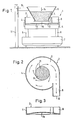
- Fig. 1 schematisch in Seitenansicht das zur Durchführung des Verfahrens gemäß der Erfindung vorgesehene Dosiergerät;
- Fig. 2 den Schwingtopf in Draufsicht und
- Fig. 3 eine abgewandelte Ausführungsform des Schwingtopfes im Querschnitt.
- Figure 1 shows schematically in side view the metering device provided for carrying out the method according to the invention;
- Fig. 2, the rocker in plan view
- Fig. 3 shows a modified embodiment of the oscillating pot in cross section.
Wie aus der Zeichnung ersichtlich, weist das dargestellte Dosiergerät 1 einen Schwingtopf 2 auf, der weitgehend zylinderförmig mit Boden 3, umlaufender Wand 4 sowie offener Oberseite ausgebildet ist. Der Schwingtopf 2 ist, vorzugsweise lösbar bzw. austauschbar, einem Halteelement 5 aufgesetzt, das eine Aufnahmekonstruktion für den Schwingtopf 2 bildet und über Federpakete 6 mit einer entsprechenden Gegenmasse 7 verbunden ist. Diese Gegenmasse 7, die durch einen Magnetantrieb oder einen Unwuchtmotor in entsprechende Vibrationen versetzt werden kann, bildet zusammen mit den Federpaketen 6 einen Schwingantrieb für den Schwingtopf 2, um diesen nach Art eines Schwingförderers in kontinuierlich vorwärtsschwingende Kreis- bzw. Spiralbewegungen zu versetzen.As can be seen from the drawing, the metering device 1 shown has a vibrating
Wie deutlich aus Fig. 2 ersichtlich, ist der Schwingtopf 2 an einer bestimmten Stelle seiner Wand 4 mit einer Auslaufrinne 8 versehen, die tangential zu dem durch die kreisförmige Wand 4 des Schwingtopfes 2 gebildeten Umfang verläuft und somit einen dosierten Abzug des aufgegebenen, aufgrund des Schwingantriebes 6, 7 in Kreisbewegung versetzten Dosiergutes 9 in Form eines Teilstromes ermöglicht. Obwohl in der Zeichnung nicht näher dargestellt, ist die Auslaufrinne 8 in ihrer Breite verstellbar ausgebildet, um hierdurch zu ermöglichen, durch einfache Verstellung des Querschnittes bzw. der Breite der Auslaufrinne 8 an deren Auslaufstelle 10 verschiedene Dosierleistungen zu erzielen. Wie aus Fig. 2 angedeutet ersichtlich, bewegt sich hierbei der dosierte Teilstrom des Dosiergutes 9 entlang einer gekrümmten, vorzugsweise teilkreisförmigen bzw. spiralförmgien Linie von der äußeren Begrenzung 11 des aufgegebenen Dosiergutes 9 bis zur Auslaufstelle 10. Hierbei bewegt sich das im Schwingtopf 2 befindliche Dosiergut 9 insgesamt in Form einer Kreisbewegung bzw. Spiralbewegung standig nach außen in Richtung der Wand 4 des Schwingtopfes 2, wobei lediglich die radial am weitesten außen gelegene Materialmenge des Dosiergutes 9 in Form des dosierten Teilstromes aus der Auslaufrinne 8 ausgetragen wird.As can be clearly seen from Fig. 2, the vibrating
Bei der abgewandelten Ausführungsform gemäß Fig. 3 weist der Schwingtopf 2 anstelle eines ebenen Bodens 3 einen nach oben gewölbten Boden 3a auf. Dadurch ist ein vollständiges Auslaufen des Dosiergutes 9 aus dem Schwingtopf 2 gewährleistet.In the modified embodiment according to FIG. 3, the
Wie aus Fig. 1 ersichtlich, ist dem Schwingtopf 2 oberseitig ein trichterförmiger Vorratsbehälter 12 für das Dosiergut 9 zugeordnet, der mit seinem unteren offenen Aus tragsende 13 im Abstand zum Boden 3 des Schwingtopfes 2 angeordnet ist.As can be seen from FIG. 1, the vibrating
Wie durch den Doppelpfeil 14 angedeutet, ist der Vorratsbehälter 12 höhenverstellbar vorgesehen. Dadurch kann der zwischen dem unteren Austragsende 13 und dem Boden 3 des Schwingtopfes 2 gebildete Zulaufspalt 15 - und damit auch die jeweilige Dosiergut-Zulaufmenge - verändert werden. Die Höhenverstellbarkeit des Vorratsbehälters 12 wird bei dem dargestellten Ausführungsbeispiel in einfacher Weise dadurch erreicht, daß dieser mittels eines Haltebügels 16 an einer Stütze 17 höhenverstellbar, beispielsweise mittels eines Schraubtriebes oder dgl., festgelegt ist.As indicated by the
Wie schließlich noch aus Fig. 1 ersichtlich, ist das untere Austragsende 13 des Vorratsbehälters 12 nach außen gebogen, um durch diese zusätzliche Maßnahme mit Sicherheit eine Brückenbildung des Dosiergutes 9 im Zulaufspalt 15 zu verhindern.As can finally be seen from FIG. 1, the
Claims (12)
dadurch gekennzeichnet,
daß das auf die Fläche aufgegebene Dosiergut in eine um die Aufgabestelle verlaufende Kreis- bzw. Spiralbewegung versetzt wird und daß von dem derart bewegten Dosiergut entlang einer gekrümmten Linie, die sich von der äußeren Begrenzung des Dosiergutes an der Aufgabestelle bis zu der Auslaufstelle erstreckt, kontinuierlich ein dosierter Teilstrom abgezogen wird.1.Procedure for the metered discharge of glass fibers and the like. Difficult-to-flow solids, in which the material to be metered is placed on a substantially flat surface at a feed point and is kept in constant motion by a continuous forward swinging movement and conveyed to a discharge point,
characterized,
that the metered material applied to the surface is set in a circular or spiral movement around the application point and that the metered product moved in this way along a curved line which extends from the outer boundary of the metered product at the application point to the outlet point a metered partial stream is withdrawn.
dadurch gekennzeichnet,
daß die gekrümmte Abzugslinie weitgehend tangential bzw. kombiniert radial/tangential zur Begrenzung des Dosiergutes an der Aufgabestelle verläuft.2. The method according to claim 1,
characterized,
that the curved withdrawal line is largely tangential or combined radially / tangentially to the limit of the dosing at the feed point.
daß sich die gekrümmte Abzugslinie in Form einer Teilkreislinie bzw. Spirallinie von der äußeren Begrenzung des Dosiergutes an der Aufgabestelle bis zur Auslaufstelle erstreckt.3. The method according to claim 1 or 2, characterized in
that the curved withdrawal line in the form of a partial circular line or spiral line extends from the outer boundary of the dosing material at the feed point to the outlet point.
daß die gekrümmte Abzugslinie wendelförmig verläuft.4. The method according to any one of claims 1 to 3, characterized in
that the curved trigger line is helical.
dadurch gekennzeichnet,
daß zum gesteuerten Dosieren die Breite des abgezogenen Teilstromes und/oder die Amplitude bzw. Frequenz der Schwingbewegung des Dosiergutes und/oder die Aufgabemenge des Dosiergutes verändert wird.5. The method according to any one of claims 1 to 4,
characterized,
that for controlled dosing the width of the sub-stream withdrawn and / or the amplitude or frequency of the oscillating movement of the dosing material and / or the quantity of the dosing material to be fed is changed.
dadurch gekennzeichnet,
daß der Schwingförderer (1) als etwa zylinderförmiger Schwingtopf (2) ausgebildet ist, der an seinem Rand (4) mit einer tangentialen Auslaufrinne (8) versehen ist.6. dosing device for carrying out the method according to one of claims 1 to 5, with a vibratory conveyor which can be set in vibration by an oscillating drive and which has a substantially flat floor for receiving the dosing material with a feed point and an outlet,
characterized,
that the vibratory conveyor (1) is designed as an approximately cylindrical vibrating pot (2), which is provided on its edge (4) with a tangential outlet channel (8).
dadurch gekennzeichnet,
daß der Boden (3a) des Schwingtopfes (2) nach oben gewölbt ausgebildet ist.7. dosing device according to claim 6,
characterized,
that the bottom (3a) of the oscillating pot (2) is curved upwards.
dadurch gekennzeichnet,
daß die Auslaufrinne (8) in ihrer Breite verstellbar ist.8. dosing device according to claim 6 or 7,
characterized,
that the outlet channel (8) is adjustable in width.
dadurch gekennzeichnet,
daß die Auslaufrinne (8), beginnend am Topfboden (3), wendelförmig entlang der Wand (4) des Schwingtopfes (2) ansteigt.9. dosing device according to one of claims 6 to 8,
characterized,
that the outlet channel (8), starting at the bottom of the pot (3), rises helically along the wall (4) of the oscillating pot (2).
dadurch gekennzeichnet,
daß oberhalb des Schwingtopfes (2) ein trichterförmiger Vorratsbehälter (12) für das Dosiergut (9) vorgesehen ist, dessen unteres offenes Austragsende (13) an der Aufgabestelle im Abstand zum Boden (3) des Schwingtopfes (2) angeordnet ist.10. dosing device according to one of claims 6 to 9,
characterized,
that a funnel-shaped storage container (12) for the dosing material (9) is provided above the oscillating pot (2), whose lower open discharge end (13) is arranged at the feed point at a distance from the bottom (3) of the oscillating pot (2).
dadurch gekennzeichnet,
daß der Vorratsbehälter (12) gegenüber dem Schwingtopf (2) höhenverstellbar ist.11. dosing device according to claim 10,
characterized,
that the storage container (12) is adjustable in height relative to the oscillating pot (2).
dadurch gekennzeichnet,
daß der Vorratsbehälter (12) an seinem unteren Austragsende (13) einen nach außen gebogenen Rand aufweist.12. dosing device according to claim 10 or 11,
characterized,
that the storage container (12) has an outwardly curved edge at its lower discharge end (13).
Applications Claiming Priority (2)
| Application Number | Priority Date | Filing Date | Title |
|---|---|---|---|
| DE3813109A DE3813109C1 (en) | 1988-04-19 | 1988-04-19 | |
| DE3813109 | 1988-04-19 |
Publications (1)
| Publication Number | Publication Date |
|---|---|
| EP0338203A1 true EP0338203A1 (en) | 1989-10-25 |
Family
ID=6352380
Family Applications (1)
| Application Number | Title | Priority Date | Filing Date |
|---|---|---|---|
| EP89102582A Withdrawn EP0338203A1 (en) | 1988-04-19 | 1989-02-15 | Method and device for the dosed discharge of glass fibres and similar not easily flowing solids |
Country Status (2)
| Country | Link |
|---|---|
| EP (1) | EP0338203A1 (en) |
| DE (1) | DE3813109C1 (en) |
Families Citing this family (3)
| Publication number | Priority date | Publication date | Assignee | Title |
|---|---|---|---|---|
| DE4116327C2 (en) * | 1991-05-17 | 1994-05-05 | Schenck Ag Carl | Dosing device for glass fibers |
| DE10121034B4 (en) * | 2001-04-25 | 2005-08-25 | Bayer, René | Device for the continuous dosing of chips and fiber material |
| DE102020118707B3 (en) | 2020-07-15 | 2021-07-08 | CiTEX Holding GmbH | Vibratory conveyor device and method for vibratory conveying of bulk material |
Citations (2)
| Publication number | Priority date | Publication date | Assignee | Title |
|---|---|---|---|---|
| DE1279537B (en) * | 1963-11-27 | 1968-10-03 | Carrier Mfg Company | Device for discharging pourable material |
| EP0083227A1 (en) * | 1981-12-25 | 1983-07-06 | Kabushiki Kaisha Ishida Koki Seisakusho | Combinatorial weighing apparatus |
Family Cites Families (7)
| Publication number | Priority date | Publication date | Assignee | Title |
|---|---|---|---|---|
| DE974312C (en) * | 1945-07-13 | 1960-11-17 | Syntron Company | Spiral conveyor |
| US3225963A (en) * | 1964-12-07 | 1965-12-28 | Vasken F Arpajian | Hopper apparatus and method |
| DE1274970B (en) * | 1967-01-17 | 1968-08-08 | Schaeffler Ohg Industriewerk | Vibratory conveyor |
| US3599783A (en) * | 1969-06-20 | 1971-08-17 | Burgess & Associates Inc | Disentangling device for separating entangled parts |
| DE7034558U (en) * | 1970-09-17 | 1972-03-23 | Schaeffler Ohg Industriewerk | VIBRATION CONVEYOR. |
| DE2806331C2 (en) * | 1978-02-15 | 1983-01-27 | Feldpausch GmbH & Co KG, 5880 Lüdenscheid | Vibratory feeder |
| US4392591A (en) * | 1980-11-13 | 1983-07-12 | Geosource Inc. | Apparatus for metering semi-flowable material |
-
1988
- 1988-04-19 DE DE3813109A patent/DE3813109C1/de not_active Expired
-
1989
- 1989-02-15 EP EP89102582A patent/EP0338203A1/en not_active Withdrawn
Patent Citations (2)
| Publication number | Priority date | Publication date | Assignee | Title |
|---|---|---|---|---|
| DE1279537B (en) * | 1963-11-27 | 1968-10-03 | Carrier Mfg Company | Device for discharging pourable material |
| EP0083227A1 (en) * | 1981-12-25 | 1983-07-06 | Kabushiki Kaisha Ishida Koki Seisakusho | Combinatorial weighing apparatus |
Also Published As
| Publication number | Publication date |
|---|---|
| DE3813109C1 (en) | 1989-08-17 |
Similar Documents
| Publication | Publication Date | Title |
|---|---|---|
| DE3800565C2 (en) | ||
| DE4018906A1 (en) | METHOD AND DEVICE FOR FOLLOWING FOLLOWING FLAT PRODUCTS | |
| DE3206544C2 (en) | ||
| EP0432190B1 (en) | Bulk material feeding device for mass flow dosing apparatus | |
| DE1160792B (en) | Device for the uniform delivery of a conveyor line with mainly flat items | |
| EP0076790B1 (en) | Device for the dosed charging of a continuous-casting mould with casting flux | |
| EP2304394B1 (en) | Dosing device for powdery substances | |
| DE2854177C2 (en) | Device for separating scrap parts contained in a pile | |
| EP0338203A1 (en) | Method and device for the dosed discharge of glass fibres and similar not easily flowing solids | |
| DE1938562A1 (en) | Device for separating interlocked or otherwise connected parts | |
| DE4116327C2 (en) | Dosing device for glass fibers | |
| EP0189468B1 (en) | Installation for continuously supplying fractionated solid materials to a treatment machine | |
| DE2052013C3 (en) | Vibrating spreading device | |
| DE2134803A1 (en) | Method and device for sorting and separating granular good mixes | |
| DE3516909C2 (en) | Cigarette making machine | |
| EP0434995B1 (en) | Silo with a discharging device | |
| DE102019134920B4 (en) | Activating agent for dosing device | |
| DE2501916A1 (en) | FLOW REGULATION AND CLASSIFICATION DEVICE FOR A FUNNEL | |
| DE3231464A1 (en) | METHOD AND DEVICE FOR FEEDING TOBACCO INTO A TOBACCO CUTTING MACHINE | |
| DE2950923C2 (en) | Device for the continuous application of a pulpy mixture on flat molds for the production of cement-bonded chipboard | |
| DE3520280C1 (en) | Discharging device having a discharging conveyor worm | |
| DE2542886A1 (en) | DEVICE FOR POWDER CONVEYING AT A DEVICE FOR CRYSTAL ZUTING ACCORDING TO VERNEUIL | |
| DE3435026A1 (en) | Device for avoiding overloading of conveying devices | |
| CH632973A5 (en) | Method and apparatus for separating suspended components or components which are adhering to each other | |
| DE2813106A1 (en) | DEVICE FOR CONTINUOUS FILLING OF TOBACCO CIGARETTE MACHINES |
Legal Events
| Date | Code | Title | Description |
|---|---|---|---|
| PUAI | Public reference made under article 153(3) epc to a published international application that has entered the european phase |
Free format text: ORIGINAL CODE: 0009012 |
|
| AK | Designated contracting states |
Kind code of ref document: A1 Designated state(s): AT BE CH DE ES FR GB GR IT LI LU NL SE |
|
| 17P | Request for examination filed |
Effective date: 19891123 |
|
| 17Q | First examination report despatched |
Effective date: 19901130 |
|
| STAA | Information on the status of an ep patent application or granted ep patent |
Free format text: STATUS: THE APPLICATION HAS BEEN WITHDRAWN |
|
| 18W | Application withdrawn |
Withdrawal date: 19910207 |