EP0337972A2 - A method and device for the supply of conditioned air - Google Patents
A method and device for the supply of conditioned air Download PDFInfo
- Publication number
- EP0337972A2 EP0337972A2 EP89850115A EP89850115A EP0337972A2 EP 0337972 A2 EP0337972 A2 EP 0337972A2 EP 89850115 A EP89850115 A EP 89850115A EP 89850115 A EP89850115 A EP 89850115A EP 0337972 A2 EP0337972 A2 EP 0337972A2
- Authority
- EP
- European Patent Office
- Prior art keywords
- air
- floor surface
- supply
- level
- beneath
- Prior art date
- Legal status (The legal status is an assumption and is not a legal conclusion. Google has not performed a legal analysis and makes no representation as to the accuracy of the status listed.)
- Granted
Links
Images
Classifications
-
- F—MECHANICAL ENGINEERING; LIGHTING; HEATING; WEAPONS; BLASTING
- F24—HEATING; RANGES; VENTILATING
- F24F—AIR-CONDITIONING; AIR-HUMIDIFICATION; VENTILATION; USE OF AIR CURRENTS FOR SCREENING
- F24F13/00—Details common to, or for air-conditioning, air-humidification, ventilation or use of air currents for screening
- F24F13/02—Ducting arrangements
- F24F13/06—Outlets for directing or distributing air into rooms or spaces, e.g. ceiling air diffuser
-
- F—MECHANICAL ENGINEERING; LIGHTING; HEATING; WEAPONS; BLASTING
- F24—HEATING; RANGES; VENTILATING
- F24F—AIR-CONDITIONING; AIR-HUMIDIFICATION; VENTILATION; USE OF AIR CURRENTS FOR SCREENING
- F24F3/00—Air-conditioning systems in which conditioned primary air is supplied from one or more central stations to distributing units in the rooms or spaces where it may receive secondary treatment; Apparatus specially designed for such systems
- F24F3/044—Systems in which all treatment is given in the central station, i.e. all-air systems
Definitions
- the present invention relates to a method for supplying conditioned air to one or more locations on a particular floor or story of an apartment building, or block of flats, with the aid of air conditioning plant equipment supplied with circulated air, and a box-like supply air terminal device which is located on, or capable of being placed on or in the vicinity of, the floor surface of said apartment floor or story.
- the invention also relates to a box-like air supply terminal device, and more specifically to a device of the kind set forth in the preamble of claim 6.
- Known air conditioning and air delivering methods and apparatus of the aforesaid kind are instrumental in causing draughts and in generating noise, particularly when the supply air terminal device is provided with separates fans or blowers. Furthermore, the known methods and apparatus have relatively poor ventilation efficiency, and consequently the occupied areas of a room or location served by such apparatus are not free from impurities and it is necessary to supply the air conditioning plant with air which is relatively pure, which further adds to the load on the plant. Exhaust air from the location served by the plant has, instead, exhibited a relatively low degree of contamination.
- An object of the present invention is to eliminate the drawbacks of the aforesaid and other known systems, and to provide an improved air supply system, which, among other things, will enable air flow and air temperature to be controlled separately and effectively in individual supply air terminal devices, thereby achieving high ventilation efficiency and high temperature efficiency.
- a further object is to provide an air supply system which will create an improved environment and climate, particular in occupied areas of a room served by the inventive system, while simultaneously facilitating operation of the air conditioning system and improving the efficiency thereof.
- air present in said location will be layered in varying degrees of impurity, therewith primarily improving the climate of the occupied zone of the location.
- Contaminated air gathers or collects at a high level, close to the ceiling of the room served by the system and is withdrawn from said location through exhaust air terminal devices installed at this level.
- the air present in the centre of the occupied zone or area of said location has a relatively high degree of purity and the air conditioning plant is supplied with circulation air of this kind, thereby relieving the plant of load to a commensurate extent.
- the air cleansed in the plant is supplied to the space located immediately beneath the floor, where said air is mixed effectively with directly supplied fresh air.
- Supply air terminal devices positioned as desired in the location served by the plant will ensure that this mixture of fresh air and clean, treated air will be supplied to the room or location at a low level therein, in the absence of draughts and while being fully controlled, which in turn assists in the aforesaid layering of the air in said room.
- the supply air is supplied at a level lower than 1.2 meters, i.e. at a level of about 1 meter above floor surface level, and that the circulation air is supplied to the plant at a level beneath 2.2 meters, preferably at a level of about 2 meters above floor surface level.
- One or more exhaust air terminal devices will preferably be located at a higher position in the location or room served by the air conditioning plant, preferably in the vicinity of the ceiling of the room.
- fresh air is preferably mixed with the treated air in the space located beneath the floor of the room, referred to hereinafter as the floor cavity.
- a substantially constant pressure is maintained in the floor cavity, preferably by controlling the speed of a fan or blower included in the air conditioning plant.
- the floor cavity has mounted therein a pressure sensor which is connected to the fan motor, via a control device, such as to ensure that the floor cavity will be maintained at a set pressure level. It is ensured in this way that all supply air terminal devices in the room or location being served will be supplied with air at a constant, predetermined pressure, which in turn will ensure that said devices will operate efficiently and reliably and each in a predetermined manner.
- each supply air terminal device may be provided with a heater, so that if low ambient temperatures are constantly recorded, despite adjustments to the throttle valves, the supply air can be heated before being delivered to the room.
- the throttle valves will have the opposite function, i.e. a greater heating requirement will result in a corresponding wider opening of the valves.
- the mixture of air treated in the air conditioning plant and fresh air will be delivered to the supply air terminal device through a centrally positioned sound insulated conduit and, subsequent to be turned through 180° in the vicinity of a throttle valve in the region of the upper part of the conduit, will be caused to depart from the device through holes or slots provided in one or more sides of the device, without increasing in pressure in said device.
- This method of supplying air to the supply air terminal devices and the surrounding area will effectively dampen noise and will also ensure that the air leaving a supply aterminal device has a low impulse, i.e. creates practically no draughts, not even in the immediate vicinity of the device.
- a supply air terminal device of the aforedescribed kind can be positioned adjacent working positions in the room or location served by the system, e.g. adjacent a desk.
- the supply air devices may be given a form such that they themselves form part of the actual work place, i.e. in practice have the same height as a desk and form a work surface or some other surface contiguous with a desk surface.
- these cables are taken up from the floor cavity through a space in respective supply air terminal devices provided especially for this purpose.
- the fan of the air conditioning plant is preferably located in or in the immediate vicinity of the floor cavity. This will enable the treated air to be supplied effectively to the floor cavity without creating a drop in air pressure as a result of further deflection air flow.
- the floor cavity concerned is preferably covered with flooring tiles, slabs or the like in accordance with a module system to which the outlet part of the air-conditioning unit and the connecting parts of the supply air terminal device are also adapted.
- the outlet part of said unit may be given an area which corresponds in cross-section to the area of one or a certain number of flooring tiles, which also applies to the connecting bases or plinths of the air supply terminal devices.
- the invention also relates to an air supply terminal device which can be positioned adjacent to or on the floor surface of a room or location, the main characterising features of said device being set forth in the characterising clause of claim 6.
- Figure 1 shows part of a floor, or story, of an office block which includes a number of offices partitioned by walls 1. Located centrally on the illustrated floor of the office block is an air conditioning unit 2, which has a vertical extension of about 2 meters from floor surface level.
- Circulated air is introduced into the unit 2, through the top thereof, and is there filtered and cooled, before being passed to a cavity 3 beneath the floor surface 4 of the room or location.
- the floor surface 4 comprises a multiple of square flooring tiles 5.
- the area of each flooring tile corresponds to the cross-sectional area of the unit 2, which means that only one tile is removed in the place where the unit 2 is to stand.
- the flooring tiles may optionally be divided into sections, one or more of which will correspond to the cross-sectional area of the base parts or plinths on which the air supply terminal devices used are supported, these devices being generally referenced 10 in the drawings.
- An inventive air supply terminal device will be described in more detail hereinafter.
- the arrows 7 drawn in the floor cavity indicate that the conditioned air leaving the unit 2 will spread throughout the cavity 3.
- fresh air is also delivered to the floor cavity 3, through a fresh air conduit 8 which is perforated with holes 9 and located adjacent the unit 2, such that air leaving the unit will be mixed with the fresh air in the conduit 8.
- the cut-away area in Figure 2 illustrates the approximate size of the mixing zone thus achieved.
- the illustrated terminal device 10 has a main body part 11, a base or plinth 12 and a top cover 13, which may be located on a level with the top of the desk 20 and therewith itself serve as the desk top or desk working surface.
- the device 10 also includes a centrally positioned air supply channel 14, which is lined with sound absorbing material and which widens out in the region of the base 12, to form a lower connecting part 14a.
- the device 10 further comprises two side panels 16, which are perforated with outlet holes 15, and a front panel 17, which is also perforated with outlet holes.
- the outlet holes 15 are arranged in vertical columns and outwardly of each such column there is found a vertically extending plate 18 with inwardly bent end parts. This arrangement will ensure that the air is delivered to the surroundings gently, at a low impulse and that the air will be mixed well with the ambient room air.
- a throttle valve 21 Arranged in the device 10 is a throttle valve 21 which comprises two curved parts 21a and 21b and which is controlled by a temperature sensor 22 in a manner to regulate the quantity of air delivered to the surroundings.
- a temperature sensor 22 When the prevailing room temperature is low, the setting of the valve will be adjusted accordingly, so as to deliver a minimum air flow.
- valve parts 21a and 21b deflect the air entering from the channel 14 through 180°.
- the inner, upper corners of the air supply terminal device are curved commensurately, so as achieve deflection of the air flow substantially in the absence of turbulence.
- valve parts 21a and 21b guide the major part of the incoming air flow towards the two opposing vertical side panels 16, whereas a minor part of the air flow departs through the holes 15 located in the front panel 17.
- the fourth side panel 23 of the box-like air supply terminal device consists in a vertically displaceable wall element which defines a space 24 in the device. This space is intended for the accommodation of telephone cables and electric cables 24 extending to the work place concerned. Such a cable arrangement 24 drawn through the floor cavity 3 is also shown in Figure 1.
- the space 24 in the device 10 is also defined on its inwardly located side by a partition wall 25 adjacent the inlet channel 14.
- the main part of the device 10 is moveable vertically in relation to the plinth or base 12. This will enable the device to be given a desired vertical extension within certain limits, e.g. so that the top surface or panel 13 of the device will coincide with the level of the work surface of the desk 20.
- the main part of the device can be detachably secured to the base 12 with the aid of pins 27 which pass through holes provided in said base.
- a nozzle 30 capable of distributing the supply air uniformly along the surfaces of the device is fitted into each of the holes 15.
- the reference numeral 31 identifies an electric heater for heating the supply air, when necessary or so desired, e.g. during the winter months.
- the aforesaid valve 21 will function in reverse, i.e. the valve will be opened wider at lower temperatures.
- the air conditioning unit 2 illustrated in Figure 3 is fitted with an air filter 35 which is effective in filtering the supplied circulated air, the filtered air subsequently being treated in a heating/cooling battery 36.
- a variable speed fan 37 is effective in moving the air to the cavity 3 beneath the floor surface 4.
- the pressure prevailing in the floor cavity 3 is sensed by means of a sensor, not shown.
- a control device which, in response thereto, increases the speed of the fan so as to maintain the pressure at a predetermined level.
- the supply air terminal devices will also deliver air at a level beneath 1 meter, whereas the circulating air is supplied to the unit 2 at a level which is approximately twice this height above floor level, i.e. at a level as high as about 2 meters.
- Contaminated air will gather in a region slightly beneath the ceiling of the room and is vented therefrom through an exhaust air terminal device 38.
- the system assumes that the various locations or rooms on the floor or story of the building served by the system communicate with each other, e.g. through appropriate gratings fitted above respective doors.
- the high quality of the air achieved when practising the inventive method is due to the fact that the circulated air is introduced into the unit 2 at a level which is located in the occupied zone of a room or location, whereas contaminated air which collects immediately beneath the ceiling of said room is discharged through exhaust air terminal devices located on a corresponding level.
- the pressure of the air in the floor cavity 3 may be from 20 to 30 Pa.
- An excessively high pressure in said cavity may create sealing problems in the overlying floor surface. It may also result in problematic noise levels.
- the illustrated configuration of the supply air terminal device provides an advantageous solution to the type of problem described in the foregoing.
Abstract
Description
- The present invention relates to a method for supplying conditioned air to one or more locations on a particular floor or story of an apartment building, or block of flats, with the aid of air conditioning plant equipment supplied with circulated air, and a box-like supply air terminal device which is located on, or capable of being placed on or in the vicinity of, the floor surface of said apartment floor or story.
- The invention also relates to a box-like air supply terminal device, and more specifically to a device of the kind set forth in the preamble of claim 6.
- Known air conditioning and air delivering methods and apparatus of the aforesaid kind are instrumental in causing draughts and in generating noise, particularly when the supply air terminal device is provided with separates fans or blowers. Furthermore, the known methods and apparatus have relatively poor ventilation efficiency, and consequently the occupied areas of a room or location served by such apparatus are not free from impurities and it is necessary to supply the air conditioning plant with air which is relatively pure, which further adds to the load on the plant. Exhaust air from the location served by the plant has, instead, exhibited a relatively low degree of contamination.
- Other drawbacks associated with the known apparatus and methods reside in limited flexibilty, insomuch that the supply air terminal device cannot be readily placed in desired positions on the apartment floor (story) or room to be served by the device. The construction of the supply air terminal devices of existing systems is also relatively complicated, which has further added to the cost of these systems.
- Examples of the present standpoint of techniques will be found in "VVS & Energy", No. 1, January 1986; Stockholm, Sweden, Bengt Bergqvist and Engelbrekt; "KLIMATSYSTEM AND BYGGNAD I SAMVERKAN", pages 71-75, particularly page 74, "Deplacerande inblåsning"; "VVS & Energy", No. 9, September 1983, Stockholm. , Sweden, Ragnar Järmer, "Deplacerande ventilation", pages 29-31, and Katalog 84/85 BAHCO Ventilation", July 1984, Enköping, Sweden, "System Floormaster", pages 17:1.1-17:1.4 and "Tilluftsdon GKF" pages 13:5:1-13:5.4.
- An object of the present invention is to eliminate the drawbacks of the aforesaid and other known systems, and to provide an improved air supply system, which, among other things, will enable air flow and air temperature to be controlled separately and effectively in individual supply air terminal devices, thereby achieving high ventilation efficiency and high temperature efficiency.
- A further object is to provide an air supply system which will create an improved environment and climate, particular in occupied areas of a room served by the inventive system, while simultaneously facilitating operation of the air conditioning system and improving the efficiency thereof.
- These and other objects are fulfilled by the inventive method, the main characterising features of which are set forth in the characterising clause of claim 1.
- Because the air is supplied to the location being served by the system at a relatively low story at the same time as the circulation air is supplied to the air conditioning plant at a level below that at which the exhaust air leaves said location, air present in said location will be layered in varying degrees of impurity, therewith primarily improving the climate of the occupied zone of the location. Contaminated air gathers or collects at a high level, close to the ceiling of the room served by the system and is withdrawn from said location through exhaust air terminal devices installed at this level. The air present in the centre of the occupied zone or area of said location has a relatively high degree of purity and the air conditioning plant is supplied with circulation air of this kind, thereby relieving the plant of load to a commensurate extent.
- The air cleansed in the plant is supplied to the space located immediately beneath the floor, where said air is mixed effectively with directly supplied fresh air. Supply air terminal devices positioned as desired in the location served by the plant will ensure that this mixture of fresh air and clean, treated air will be supplied to the room or location at a low level therein, in the absence of draughts and while being fully controlled, which in turn assists in the aforesaid layering of the air in said room.
- In practice, it is preferred that the supply air is supplied at a level lower than 1.2 meters, i.e. at a level of about 1 meter above floor surface level, and that the circulation air is supplied to the plant at a level beneath 2.2 meters, preferably at a level of about 2 meters above floor surface level.
- One or more exhaust air terminal devices will preferably be located at a higher position in the location or room served by the air conditioning plant, preferably in the vicinity of the ceiling of the room.
- As before indicated, when applying the inventive method, fresh air is preferably mixed with the treated air in the space located beneath the floor of the room, referred to hereinafter as the floor cavity. In this respect, a substantially constant pressure is maintained in the floor cavity, preferably by controlling the speed of a fan or blower included in the air conditioning plant.
- The floor cavity has mounted therein a pressure sensor which is connected to the fan motor, via a control device, such as to ensure that the floor cavity will be maintained at a set pressure level. It is ensured in this way that all supply air terminal devices in the room or location being served will be supplied with air at a constant, predetermined pressure, which in turn will ensure that said devices will operate efficiently and reliably and each in a predetermined manner.
- If the temperature in the room or location should fall in the winter months, this will be registered by the thermostat or thermostats which controls or control the throttle valves of the air supply terminal devices, so as to throttle the flow of supply air to a commensurate extent. Each supply air terminal device may be provided with a heater, so that if low ambient temperatures are constantly recorded, despite adjustments to the throttle valves, the supply air can be heated before being delivered to the room. In this case, the throttle valves will have the opposite function, i.e. a greater heating requirement will result in a corresponding wider opening of the valves.
- In practice, the mixture of air treated in the air conditioning plant and fresh air will be delivered to the supply air terminal device through a centrally positioned sound insulated conduit and, subsequent to be turned through 180° in the vicinity of a throttle valve in the region of the upper part of the conduit, will be caused to depart from the device through holes or slots provided in one or more sides of the device, without increasing in pressure in said device.
- This method of supplying air to the supply air terminal devices and the surrounding area will effectively dampen noise and will also ensure that the air leaving a supply aterminal device has a low impulse, i.e. creates practically no draughts, not even in the immediate vicinity of the device.
- This means in practice that a supply air terminal device of the aforedescribed kind can be positioned adjacent working positions in the room or location served by the system, e.g. adjacent a desk. In fact the supply air devices may be given a form such that they themselves form part of the actual work place, i.e. in practice have the same height as a desk and form a work surface or some other surface contiguous with a desk surface.
- Particular advantages are afforded when the electric cables, telephone cables, etc, leading to various equipment in the room or location served by the system are located in the floor cavity. According to one preferred embodiment of the invention, these cables are taken up from the floor cavity through a space in respective supply air terminal devices provided especially for this purpose.
- This will enable cables to be drawn directly to or to the immediate vicinity of tele-computer equipment and the like placed on a desk top and therewith obviate the problem of tangled cables, which is normal in most cable arrangements of this kind.
- The fan of the air conditioning plant is preferably located in or in the immediate vicinity of the floor cavity. This will enable the treated air to be supplied effectively to the floor cavity without creating a drop in air pressure as a result of further deflection air flow.
- The floor cavity concerned is preferably covered with flooring tiles, slabs or the like in accordance with a module system to which the outlet part of the air-conditioning unit and the connecting parts of the supply air terminal device are also adapted. Thus, the outlet part of said unit may be given an area which corresponds in cross-section to the area of one or a certain number of flooring tiles, which also applies to the connecting bases or plinths of the air supply terminal devices.
- Thus, when installing an air supply terminal device, it is only necessary to remove one or a requisite number of flooring tiles at the appropriate location in a room and to subsequently connect up and seal the device. This affords considerable flexibility to the system and enables modifications to be made readily, for instance when positional changes are to be made in the system of a location, room, or of an apartment floor in a block of apartments.
- The invention also relates to an air supply terminal device which can be positioned adjacent to or on the floor surface of a room or location, the main characterising features of said device being set forth in the characterising clause of claim 6.
- Further characterising features of the invention and other advantages afforded thereby will be apparent from the following description of selected embodiments of the invention.
- The description is given with reference to the accompanying drawings.
-
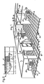
- Figure 1 is a perspective view which illustrates part of one floor, or story, of an office block, and shows a number of offices supplied with air that has been conditioned with the aid of the inventive air conditioning system;
- Figure 2 is a plan view of part of the floor, or story, shown in Figure 1 and illustrates the supply of fresh air to and the mixture of said air with air which has been processed in accordance with the invention;
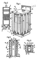
- Figure 3 is a sectional view of an air conditioning unit forming part of the air supply system;
- Figure 4 illustrates in perspective a box-shaped air supply terminal device according to the invention;
- Figure 5 is a sectional view taken on the line V-V in Figure 4; and
- Figure 6 is a sectional view taken on the line VI-VI in Figure 5.
- Figure 1 shows part of a floor, or story, of an office block which includes a number of offices partitioned by walls 1. Located centrally on the illustrated floor of the office block is an
air conditioning unit 2, which has a vertical extension of about 2 meters from floor surface level. - Circulated air is introduced into the
unit 2, through the top thereof, and is there filtered and cooled, before being passed to a cavity 3 beneath thefloor surface 4 of the room or location. Thefloor surface 4 comprises a multiple of square flooring tiles 5. In the case of the illustrated embodiment, the area of each flooring tile corresponds to the cross-sectional area of theunit 2, which means that only one tile is removed in the place where theunit 2 is to stand. - The flooring tiles may optionally be divided into sections, one or more of which will correspond to the cross-sectional area of the base parts or plinths on which the air supply terminal devices used are supported, these devices being generally referenced 10 in the drawings. An inventive air supply terminal device will be described in more detail hereinafter. The arrows 7 drawn in the floor cavity indicate that the conditioned air leaving the
unit 2 will spread throughout the cavity 3. - As illustrated in Figure 2, fresh air is also delivered to the floor cavity 3, through a
fresh air conduit 8 which is perforated withholes 9 and located adjacent theunit 2, such that air leaving the unit will be mixed with the fresh air in theconduit 8. The cut-away area in Figure 2 illustrates the approximate size of the mixing zone thus achieved. - When wishing to supply conditioned air to a selected area in a room or other location on the floor or story served by the system, e.g. a working area around a
desk 20 for instance, part of a flooring tile 5 is removed and an air supply terminal device of the kind illustrated in Figure 4 is fitted over the space thus exposed. - The illustrated
terminal device 10 has amain body part 11, a base orplinth 12 and atop cover 13, which may be located on a level with the top of thedesk 20 and therewith itself serve as the desk top or desk working surface. - As shown in Figures 5 and 6, the
device 10 also includes a centrally positionedair supply channel 14, which is lined with sound absorbing material and which widens out in the region of thebase 12, to form a lower connecting part 14a. - The
device 10 further comprises twoside panels 16, which are perforated with outlet holes 15, and a front panel 17, which is also perforated with outlet holes. The outlet holes 15 are arranged in vertical columns and outwardly of each such column there is found a vertically extendingplate 18 with inwardly bent end parts. This arrangement will ensure that the air is delivered to the surroundings gently, at a low impulse and that the air will be mixed well with the ambient room air. - Arranged in the
device 10 is a throttle valve 21 which comprises twocurved parts 21a and 21b and which is controlled by a temperature sensor 22 in a manner to regulate the quantity of air delivered to the surroundings. When the prevailing room temperature is low, the setting of the valve will be adjusted accordingly, so as to deliver a minimum air flow. - The
valve parts 21a and 21b deflect the air entering from thechannel 14 through 180°. The inner, upper corners of the air supply terminal device are curved commensurately, so as achieve deflection of the air flow substantially in the absence of turbulence. - The
valve parts 21a and 21b guide the major part of the incoming air flow towards the two opposingvertical side panels 16, whereas a minor part of the air flow departs through theholes 15 located in the front panel 17. - The
fourth side panel 23 of the box-like air supply terminal device consists in a vertically displaceable wall element which defines aspace 24 in the device. This space is intended for the accommodation of telephone cables andelectric cables 24 extending to the work place concerned. Such acable arrangement 24 drawn through the floor cavity 3 is also shown in Figure 1. - The
space 24 in thedevice 10 is also defined on its inwardly located side by apartition wall 25 adjacent theinlet channel 14. The main part of thedevice 10 is moveable vertically in relation to the plinth orbase 12. This will enable the device to be given a desired vertical extension within certain limits, e.g. so that the top surface orpanel 13 of the device will coincide with the level of the work surface of thedesk 20. The main part of the device can be detachably secured to the base 12 with the aid ofpins 27 which pass through holes provided in said base. - A
nozzle 30 capable of distributing the supply air uniformly along the surfaces of the device is fitted into each of theholes 15. - The reference numeral 31 identifies an electric heater for heating the supply air, when necessary or so desired, e.g. during the winter months. When the heater is in use, the aforesaid valve 21 will function in reverse, i.e. the valve will be opened wider at lower temperatures.
- The
air conditioning unit 2 illustrated in Figure 3 is fitted with anair filter 35 which is effective in filtering the supplied circulated air, the filtered air subsequently being treated in a heating/cooling battery 36. Avariable speed fan 37 is effective in moving the air to the cavity 3 beneath thefloor surface 4. The pressure prevailing in the floor cavity 3 is sensed by means of a sensor, not shown. When a tendency towards lower pressure is sensed in the floor cavity, an impulse is sent to a control device which, in response thereto, increases the speed of the fan so as to maintain the pressure at a predetermined level. - It will be seen from Figure 1 that the supply air terminal devices will also deliver air at a level beneath 1 meter, whereas the circulating air is supplied to the
unit 2 at a level which is approximately twice this height above floor level, i.e. at a level as high as about 2 meters. Contaminated air will gather in a region slightly beneath the ceiling of the room and is vented therefrom through an exhaustair terminal device 38. The system assumes that the various locations or rooms on the floor or story of the building served by the system communicate with each other, e.g. through appropriate gratings fitted above respective doors. - The high quality of the air achieved when practising the inventive method is due to the fact that the circulated air is introduced into the
unit 2 at a level which is located in the occupied zone of a room or location, whereas contaminated air which collects immediately beneath the ceiling of said room is discharged through exhaust air terminal devices located on a corresponding level. - In practice, the pressure of the air in the floor cavity 3 may be from 20 to 30 Pa. An excessively high pressure in said cavity may create sealing problems in the overlying floor surface. It may also result in problematic noise levels.
- However, the illustrated configuration of the supply air terminal device provides an advantageous solution to the type of problem described in the foregoing.
Claims (11)
Applications Claiming Priority (2)
| Application Number | Priority Date | Filing Date | Title |
|---|---|---|---|
| SE8801334A SE467019B (en) | 1988-04-11 | 1988-04-11 | SEAT AND SUPPLY DOWN DEPLACING VENTILATION |
| SE8801334 | 1988-04-11 |
Publications (3)
| Publication Number | Publication Date |
|---|---|
| EP0337972A2 true EP0337972A2 (en) | 1989-10-18 |
| EP0337972A3 EP0337972A3 (en) | 1990-08-29 |
| EP0337972B1 EP0337972B1 (en) | 1994-02-02 |
Family
ID=20371974
Family Applications (1)
| Application Number | Title | Priority Date | Filing Date |
|---|---|---|---|
| EP19890850115 Expired - Lifetime EP0337972B1 (en) | 1988-04-11 | 1989-04-10 | A method and device for the supply of conditioned air |
Country Status (3)
| Country | Link |
|---|---|
| EP (1) | EP0337972B1 (en) |
| DE (1) | DE68912813T2 (en) |
| SE (1) | SE467019B (en) |
Cited By (3)
| Publication number | Priority date | Publication date | Assignee | Title |
|---|---|---|---|---|
| FR2690511A1 (en) * | 1992-04-24 | 1993-10-29 | Levavasseur Guy | Breathable air supply delivery unit for enclosed space working - comprises two intercommunicating hollow housings, one with air intake and second with diffuser formed by perforated end section contg. supple foam material of polyurethane |
| WO1997034113A1 (en) * | 1996-03-11 | 1997-09-18 | Leif Lind | A box- or screen-like supply air terminal device and a nozzle module or nozzle unit therefor |
| CN108592186A (en) * | 2018-04-12 | 2018-09-28 | 中国建筑股份有限公司 | The microenvironment quality control system of large space |
Citations (3)
| Publication number | Priority date | Publication date | Assignee | Title |
|---|---|---|---|---|
| DE2407448A1 (en) * | 1974-02-16 | 1975-08-28 | Kessler & Luch Kg | Air conditioning plant for large areas - has under-floor air channels with take-off points with fitted couplings |
| DE2754699A1 (en) * | 1976-12-09 | 1978-06-15 | Leif Ingemar Lind | UMBRELLA TO IMPROVE THE ENVIRONMENT OF A WORKPLACE WITH MULTIPLE WORK AREAS |
| DE2938702A1 (en) * | 1979-09-25 | 1981-04-09 | LTG Luftechnische GmbH, 7000 Stuttgart | Individual room air conditioning system - has floor outlet with main nozzles and inlets for ambient air |
-
1988
- 1988-04-11 SE SE8801334A patent/SE467019B/en not_active IP Right Cessation
-
1989
- 1989-04-10 EP EP19890850115 patent/EP0337972B1/en not_active Expired - Lifetime
- 1989-04-10 DE DE1989612813 patent/DE68912813T2/en not_active Expired - Fee Related
Patent Citations (3)
| Publication number | Priority date | Publication date | Assignee | Title |
|---|---|---|---|---|
| DE2407448A1 (en) * | 1974-02-16 | 1975-08-28 | Kessler & Luch Kg | Air conditioning plant for large areas - has under-floor air channels with take-off points with fitted couplings |
| DE2754699A1 (en) * | 1976-12-09 | 1978-06-15 | Leif Ingemar Lind | UMBRELLA TO IMPROVE THE ENVIRONMENT OF A WORKPLACE WITH MULTIPLE WORK AREAS |
| DE2938702A1 (en) * | 1979-09-25 | 1981-04-09 | LTG Luftechnische GmbH, 7000 Stuttgart | Individual room air conditioning system - has floor outlet with main nozzles and inlets for ambient air |
Cited By (4)
| Publication number | Priority date | Publication date | Assignee | Title |
|---|---|---|---|---|
| FR2690511A1 (en) * | 1992-04-24 | 1993-10-29 | Levavasseur Guy | Breathable air supply delivery unit for enclosed space working - comprises two intercommunicating hollow housings, one with air intake and second with diffuser formed by perforated end section contg. supple foam material of polyurethane |
| WO1997034113A1 (en) * | 1996-03-11 | 1997-09-18 | Leif Lind | A box- or screen-like supply air terminal device and a nozzle module or nozzle unit therefor |
| US6135877A (en) * | 1996-03-11 | 2000-10-24 | Lind; Leif | Box- or screen-like supply air terminal device and a nozzle module or nozzle unit therefor |
| CN108592186A (en) * | 2018-04-12 | 2018-09-28 | 中国建筑股份有限公司 | The microenvironment quality control system of large space |
Also Published As
| Publication number | Publication date |
|---|---|
| SE8801334D0 (en) | 1988-04-11 |
| DE68912813T2 (en) | 1994-05-19 |
| SE467019B (en) | 1992-05-11 |
| EP0337972A3 (en) | 1990-08-29 |
| DE68912813D1 (en) | 1994-03-17 |
| SE8801334L (en) | 1989-10-12 |
| EP0337972B1 (en) | 1994-02-02 |
Similar Documents
| Publication | Publication Date | Title |
|---|---|---|
| US4775001A (en) | Zoned air conditioning system | |
| US7232369B2 (en) | System and method for providing heating, ventilation and air conditioning | |
| EP1146841B1 (en) | Method and device for ventilating a so called clean room | |
| US3367257A (en) | Air control for white room | |
| WO1999010685A1 (en) | Modular integrated terminals and associated systems for heating and cooling | |
| EP0207718B1 (en) | Zoned air conditioning system | |
| US5135436A (en) | Personalized air conditioning system | |
| US20130023198A1 (en) | System and method for delivering air | |
| EP0413050A1 (en) | Personalized air conditioning and a method | |
| US5346426A (en) | Method and an apparatus in ventilation | |
| EP0337972B1 (en) | A method and device for the supply of conditioned air | |
| JP3503265B2 (en) | Clean room air conditioning system | |
| US5318099A (en) | Method and apparatus for emulating a perimeter induction unit air conditioning system | |
| JP2515593B2 (en) | Clean room construction system | |
| KR200477600Y1 (en) | Apparatus for controlling supply amount and direction of air | |
| EP4008974A1 (en) | A ventilation system | |
| EP1407198B1 (en) | Ventilating system | |
| PL197670B1 (en) | A method and means to create an individually controlled climate at a separate workstation in a room having a primary climate equipment | |
| JPS6042391B2 (en) | Air conditioning system for buildings with stepped audience seating | |
| JP2003302086A (en) | Outside air supply system | |
| JP3079190B2 (en) | Partition wall fusion type total heat exchanger | |
| US20120052789A1 (en) | Personalized distribution terminal | |
| FI80517C (en) | FOERFARANDE OCH ANORDNING FOER RUMSKLIMATISERING. | |
| JPS6228375B2 (en) | ||
| JPH04106334A (en) | Air conditioner |
Legal Events
| Date | Code | Title | Description |
|---|---|---|---|
| PUAI | Public reference made under article 153(3) epc to a published international application that has entered the european phase |
Free format text: ORIGINAL CODE: 0009012 |
|
| AK | Designated contracting states |
Kind code of ref document: A2 Designated state(s): CH DE FR GB LI SE |
|
| PUAL | Search report despatched |
Free format text: ORIGINAL CODE: 0009013 |
|
| AK | Designated contracting states |
Kind code of ref document: A3 Designated state(s): CH DE FR GB LI SE |
|
| 17P | Request for examination filed |
Effective date: 19910214 |
|
| 17Q | First examination report despatched |
Effective date: 19911002 |
|
| GRAA | (expected) grant |
Free format text: ORIGINAL CODE: 0009210 |
|
| AK | Designated contracting states |
Kind code of ref document: B1 Designated state(s): CH DE FR GB LI SE |
|
| REF | Corresponds to: |
Ref document number: 68912813 Country of ref document: DE Date of ref document: 19940317 |
|
| ET | Fr: translation filed | ||
| PLBE | No opposition filed within time limit |
Free format text: ORIGINAL CODE: 0009261 |
|
| STAA | Information on the status of an ep patent application or granted ep patent |
Free format text: STATUS: NO OPPOSITION FILED WITHIN TIME LIMIT |
|
| 26N | No opposition filed | ||
| EAL | Se: european patent in force in sweden |
Ref document number: 89850115.0 |
|
| PGFP | Annual fee paid to national office [announced via postgrant information from national office to epo] |
Ref country code: GB Payment date: 19990315 Year of fee payment: 11 |
|
| PGFP | Annual fee paid to national office [announced via postgrant information from national office to epo] |
Ref country code: FR Payment date: 19990324 Year of fee payment: 11 |
|
| PGFP | Annual fee paid to national office [announced via postgrant information from national office to epo] |
Ref country code: SE Payment date: 19990325 Year of fee payment: 11 |
|
| PGFP | Annual fee paid to national office [announced via postgrant information from national office to epo] |
Ref country code: DE Payment date: 19990326 Year of fee payment: 11 Ref country code: CH Payment date: 19990326 Year of fee payment: 11 |
|
| PG25 | Lapsed in a contracting state [announced via postgrant information from national office to epo] |
Ref country code: GB Free format text: LAPSE BECAUSE OF NON-PAYMENT OF DUE FEES Effective date: 20000410 |
|
| PG25 | Lapsed in a contracting state [announced via postgrant information from national office to epo] |
Ref country code: SE Free format text: LAPSE BECAUSE OF NON-PAYMENT OF DUE FEES Effective date: 20000411 |
|
| PG25 | Lapsed in a contracting state [announced via postgrant information from national office to epo] |
Ref country code: LI Free format text: LAPSE BECAUSE OF NON-PAYMENT OF DUE FEES Effective date: 20000430 Ref country code: CH Free format text: LAPSE BECAUSE OF NON-PAYMENT OF DUE FEES Effective date: 20000430 |
|
| GBPC | Gb: european patent ceased through non-payment of renewal fee |
Effective date: 20000410 |
|
| EUG | Se: european patent has lapsed |
Ref document number: 89850115.0 |
|
| REG | Reference to a national code |
Ref country code: CH Ref legal event code: PL |
|
| PG25 | Lapsed in a contracting state [announced via postgrant information from national office to epo] |
Ref country code: FR Free format text: LAPSE BECAUSE OF NON-PAYMENT OF DUE FEES Effective date: 20001229 |
|
| PG25 | Lapsed in a contracting state [announced via postgrant information from national office to epo] |
Ref country code: DE Free format text: LAPSE BECAUSE OF NON-PAYMENT OF DUE FEES Effective date: 20010201 |
|
| REG | Reference to a national code |
Ref country code: FR Ref legal event code: ST |