EP0337593B1 - Apparatus and method for exchanging oil for device having oil pan for circulating oil therebetween - Google Patents
Apparatus and method for exchanging oil for device having oil pan for circulating oil therebetween Download PDFInfo
- Publication number
- EP0337593B1 EP0337593B1 EP89301115A EP89301115A EP0337593B1 EP 0337593 B1 EP0337593 B1 EP 0337593B1 EP 89301115 A EP89301115 A EP 89301115A EP 89301115 A EP89301115 A EP 89301115A EP 0337593 B1 EP0337593 B1 EP 0337593B1
- Authority
- EP
- European Patent Office
- Prior art keywords
- oil
- amount
- fresh
- pump
- vessel
- Prior art date
- Legal status (The legal status is an assumption and is not a legal conclusion. Google has not performed a legal analysis and makes no representation as to the accuracy of the status listed.)
- Expired - Lifetime
Links
Images

Classifications
-
- F—MECHANICAL ENGINEERING; LIGHTING; HEATING; WEAPONS; BLASTING
- F01—MACHINES OR ENGINES IN GENERAL; ENGINE PLANTS IN GENERAL; STEAM ENGINES
- F01M—LUBRICATING OF MACHINES OR ENGINES IN GENERAL; LUBRICATING INTERNAL COMBUSTION ENGINES; CRANKCASE VENTILATING
- F01M11/00—Component parts, details or accessories, not provided for in, or of interest apart from, groups F01M1/00 - F01M9/00
-
- F—MECHANICAL ENGINEERING; LIGHTING; HEATING; WEAPONS; BLASTING
- F16—ENGINEERING ELEMENTS AND UNITS; GENERAL MEASURES FOR PRODUCING AND MAINTAINING EFFECTIVE FUNCTIONING OF MACHINES OR INSTALLATIONS; THERMAL INSULATION IN GENERAL
- F16H—GEARING
- F16H57/00—General details of gearing
- F16H57/04—Features relating to lubrication or cooling or heating
- F16H57/0408—Exchange, draining or filling of transmission lubricant
-
- F—MECHANICAL ENGINEERING; LIGHTING; HEATING; WEAPONS; BLASTING
- F01—MACHINES OR ENGINES IN GENERAL; ENGINE PLANTS IN GENERAL; STEAM ENGINES
- F01M—LUBRICATING OF MACHINES OR ENGINES IN GENERAL; LUBRICATING INTERNAL COMBUSTION ENGINES; CRANKCASE VENTILATING
- F01M11/00—Component parts, details or accessories, not provided for in, or of interest apart from, groups F01M1/00 - F01M9/00
- F01M11/04—Filling or draining lubricant of or from machines or engines
- F01M11/0458—Lubricant filling and draining
-
- F—MECHANICAL ENGINEERING; LIGHTING; HEATING; WEAPONS; BLASTING
- F16—ENGINEERING ELEMENTS AND UNITS; GENERAL MEASURES FOR PRODUCING AND MAINTAINING EFFECTIVE FUNCTIONING OF MACHINES OR INSTALLATIONS; THERMAL INSULATION IN GENERAL
- F16N—LUBRICATING
- F16N31/00—Means for collecting, retaining, or draining-off lubricant in or on machines or apparatus
-
- F—MECHANICAL ENGINEERING; LIGHTING; HEATING; WEAPONS; BLASTING
- F01—MACHINES OR ENGINES IN GENERAL; ENGINE PLANTS IN GENERAL; STEAM ENGINES
- F01M—LUBRICATING OF MACHINES OR ENGINES IN GENERAL; LUBRICATING INTERNAL COMBUSTION ENGINES; CRANKCASE VENTILATING
- F01M11/00—Component parts, details or accessories, not provided for in, or of interest apart from, groups F01M1/00 - F01M9/00
- F01M11/0004—Oilsumps
Description
- The Invention relates to an apparatus and method for exchanging waste oil with fresh oil, and more particularly to the oil exchange apparatus and method for a device having an oil pan so as to circulate oil between the device and the pan, such as a hydromatic torque converter provided in motor vehicles.
- The torque converter or automatic transmission comprises a pump impeller connected with an engine output shaft to drive, through actuating oil, a turbine impeller, which is connected with a sun-and-planetary gears transmission so as to change the output torque. Since such actuating oil is subjected to severe load, fatigued oil must be exchanged after the lapse of some time period.
- Even if waste oil in a pan of the torque converter is exchanged, there is still a some amount of waste oil remained in the converter. It is, thus, necessary to drive the engine for a while, e.g. one minute for sucking up fresh oil newly supplied in the pan and exhausting waste oil remained in the converter into the pan, whereby newly supplied oil is inevitably contaminated. Such treatment must be repeated at least a few or several times in order to almost completely exchange waste oil with fresh one.
- Thus, an operator must thrust a hose nozzle for extracting waste oil to be taken into a can therefor and another hose nozzle for supplying fresh oil from another can alternately in the oil pan and each time actuate the respective pump and valve, which must be repeated a plurality of times. This is not only troublesome but also takes considerably much time.
- GB-A-1 027 250 describes an apparatus for exchanging oil while an engine is not being driven wherein a controlling means is so programmed that a first solenoid valve and pump are actuated to extract waste oil in some amount (in this case a total amount) to be taken into a first vessel through a single nozzle and a first conduit, then a second solenoid valve and pump are actuated to supply fresh oil in some amount (a total preset amount) from a second vessel through a second conduit and the single nozzle.
- It has been found to our astonishment as a result of experiments that extracting waste oil and supplying fresh oil during idly driving the engine can attain oil change in a fairly shorter time with far less labour.
- Furthermore, in the past, flowmeters have been used for metering the amount of extracting waste oil and of supplying fresh oil. This is unsatisfactory in that there occurs discrepancy between the both metered amount of extracted waste oil and supplied fresh oil, due to that the temperature of the waste oil in the oil pan is above 80°C while the temperature of the fresh oil is about 20°C and it comes to difference of the weight of the metered oils, even if the volumetric amount of the oils are exactly metered by the flowmeters. It is another cause of the discrepancy that the flowmeter will operate when the hose nozzle sucks air due to, for instance, inadequate thrust the same in the oil pan.
- An object of the invention is, thus, to provide an apparatus and method for more efficiently exchanging oil for the device of the art referred to above, based on said new finding and consequently during idly driving the engine so as to keep said device in operation to circulate oil between the device and the oil pan.
- Another object is to provide the oil exchange apparatus and method capable of ensuring the amount of oil extracted from the device and supplied thereto to be correct.
- Said objects can be attained fundamentally by the present invention. According to the invention, there is provided a method for exchanging oil by means of an apparatus comprising a pair of vessels one for waste oil to be taken and the other for fresh oil stored to supply, a pair of solenoid valves and pumps for extracting waste oil and supplying fresh oil, a pair of conduits respectively extending from said vessels through said concerned valve and pump, each other ends of which is connected to one and common nozzle, means for determining the amount of waste and fresh oil; a key board; and an indicator, the apparatus further comprising controlling means connected with the valves, pumps, indicator so as to actuate those and with the determining means and key board so as to be actuated thereby and so programmed that the first solenoid valve and pump are actuated to extract waste oil in some amount to be taken into the first vessel through the single nozzle and the first conduit, then the second solenoid valve and pump are actuated to supply fresh oil in some amount from the second vessel through the second conduit and the single nozzle,characterised in that the method is carried out during engine idling and actuation of the apparatus is paused for some time period, which is repeated a few or several times to be stopped when the total amount of the extracted and the supplied oil which is determined by the determining means reaches at a preset amount.
- According to the invention, there is also provided an apparatus for exchanging oil using the method of the invention comprising a pair of vessels one for waste oil to be taken and the other for fresh oil stored to supply; a pair of solenoid valves and pumps for extracting waste oil and supplying fresh oil; a pair of conduits respectively extending from said vessels through said concerned valve and pump, each other ends of which is connected to one and common nozzle; means for determining the amount of waste and fresh oils; a key board; and an indicator, characterised in that the apparatus further comprises controlling means connected with the valves, pumps, indicator so as to actuate those and with the determining means and key board so as to be actuated thereby and programmed to repeat the following steps during idly driving an engine a few or several times:
- (i) actuate the first solenoid valve and pump (so that waste oil is extracted and taken into the first vessel through the single nozzle;
- (ii) deactuate the first solenoid valve and pump when the extracted waste oil has reached a predetermined amount;
- (iii) actuate the second solenoid valve and pump so that that fresh oil is supplied from the second vessel through the second conduit and the single nozzle;
- (iv) deactuate the second solenoid valve and pump when the supplied fresh oil has reached a predetermined amount;
- (v) pause for a predetermined time period and to stop when the total amount of either the extracted or the supplied oil, as determined by the determining means reaches a predetermined amount;
- Said controlling means is preferably in the form of a microcomputor connected with said valves, pumps and load cells so as to proceed with repeated extracting waste oil and supplying fresh oil respectively in the amounts predetermined according to stored informations or operations of a keyboard.
- The invention will be explained in more detail in respect of preferred embodiments in reference to the accompanying drawings.
-
- Fig. 1 is a schematic front elevation partly in section of the apparatus according to the invention;
- Fig. 2 is a block diagram of the controlling means;
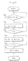
- Fig. 3 (A + B) is a flow sheet showing oil exchanged process based on the total amount of oil to be exchanged which is varied depending on the motor car type with using the apparatus and method of the invention;
- Fig. 4 is a flow sheet for judging whether or not the amount of supplied fresh oil reaches at the set amount and the amount of extracted waste oil reaches at the set amount;
- Fig. 5 is a flow sheet for making the hoses empty at the last stage of the operation.
- In reference to Fig. 1, the apparatus of the invention has six
casing walls 10 to form a substantially rectangular parallelpiped box, the interior of which is divided by a partition wall 11 into upper and lower rooms. In the upper portion of the lower room, there is mounted atransverse bar 12 between theopposite side walls load cell 13 is mounted so as to support abox 14 at the top wall thereof. Thebox 14 suspended on the load cell has opposite side walls each formed with a through hole 14' so that saidcross bar 12 extending therethrough does not prevent thebox 14 from freely moving up and down a little and a bottom wall on which awaste oil vessel 15A and afresh oil vessel 15B are placed so that the total amount of waste and fresh oils in said vessels may be determined by saidload cell 13. - A conduit 16A is extended from
said vessel 15A through a pump P1 and a solenoid valve V1 respectively mounted on said partition wall 11, the other end of which is connected with aflexible hose 17A at one end thereof via a connector fixed at theside casing wall 10, the other end of which is connected with anozzle 18, so that when said valve V1 is opened and said pump P1 is driven waste oil may be extracted from the oil pan not shown to be taken into thevessel 15A. Aconduit 16B is similarly extended from thefresh oil vessel 15B through a solenoid valve V2 and a pump P2 to be connected with a flexible hose 17B at one end thereof, of which free end is connected with said common andsingle nozzle 18, so that when said valve V2 is opened and said pump P2 is normally driven fresh oil may be supplied from thevessel 15B into the oil pan. - The apparatus is preferably provided with a plurality of
casters 19 to be freely movable toward a motor car not shown for oil exchange and apart therefrom. - On the
front casing wall 10, there is provided a panel of controlling means represented generally by 20. Said panel is provided with anindicator 21 showing the oil amount to be determined by theload cell 13, akey board 22 for actuating said controllingmeans 20 and setting the total amount of oil to be extracted and subsequently supplied, and a speaker or anyother warning device 23. - Now in reference to Fig. 2, said controlling
means 20 comprises a central processing unit CPU which is connected with the pumps P1, P2, the solenoid valves V1, V2, theload cell 13, thekey board 22 and so on through an input-output device I/O. There are furthermore arranged a read only memory ROM, a random access memory RAM and a clock respectively connected with the central processing unit CPU. - Conventionally, waste oil is extracted in a suitable amount and then a corresponding amount of fresh oil is supplied, which is repeated a plurality of times as referred to above so that some error in the oil amount in every extraction and supply step due to, for instance, the use of flowmeters and the temperature difference in the both oils may be accumulated which may lead to disadvantage in function of the device such as the torque converter, which can be avoided according to the apparatus of the invention, having the
single load cell 13 determining the total amount of waste and fresh oils. - Furthermore, it is often to fail to extract tne intended amount of waste oil due to irrelevant holding of the hose nozzle in the oil pan in the device so as to suck not oil but air. According to the apparatus of the invention, not only such failure is reduced because one and common nozzle is kept as it is during and through the oil exchange operation for both extracting and supplying, but also it is made possible for the apparatus of the invention to give warning on the irrelevant holding of the nozzle so as to make additional extracting.
- It is necessary to fill the nose for supplying fresh oil therewith before oil exchange in order to prevent waste oil from entering therein via the single nozzle when extracting waste oil, which is necessary and possible for the apparatus of the invention.
- Oil exchange method of the invention is based on the total amount of oil to be exchanged, which is naturally varied e.g. 6, 7, 8 and 9 depending on a size of the torque converter or a motor car type. Depending on said total oil amount, suitable amounts of oil firstly extracted and then supplied, and consequently extracted and then supplied as well as a time of pause in order to attain as far efficient and complete oil exchange as possible are designed e.g. as follows.
Step Total Oil Amount To Be Exchanged And Set 6 7 8 9 1st Extracted (W1) 1.5 1.5 1.5 1.5 Supplied (W2) 2.3 2.3 2.3 2.3 Pause (T1) 1 min. 1 min. 1 min. 1 min. 2nd Extracted (W3) 2.3 2.3 2.3 2.3 Supplied (W4) 2.3 2.3 2.3 2.3 Pause (T2) 4 min. 4 min. 4 min. 4 min. 3rd Extracted 2.2 2.3 2.3 2.3 Supplied 1.4 2.3 2.3 2.3 Pause 4 min. 4 min. 4 min. 4th Extracted 0.9 1.9 2.3 Supplied 0.1 1.1 2.2 Pause 4 min. 5th Extracted 0.6 Supplied Pause - In case where oil exchange process is made e.g. in respect of the small size torque converter to be operated by oil of totally 6 , in the first step 1.5 waste oil is extracted and 2.3 fresh oil is supplied, after one minute pause in the second step 2.3 oil is extracted and 2.3 oil is supplied, after four minutes pause 2.2 oil is extracted and then 1.4 oil is supplied according to this design of oil exchange, which has been stored in advance in controlling means. It is possible of course to automatically convert the weight determined by the load cell into the corresponding volume in view of the known specific gravity of oil.
- Now in reference to Fig. 3, in order to select a pattern of extraction, supply and pause e.g. "6" is inputted by actuating the
key board 22 so as to m proceed with operation as referred to above. When thrusting thesingle nozzle 18 in the oil pan of the torque converter (not shown) which is idly driven for keeping to circulate oil between the torque converter and the oil pan, and actuating a start switch of the key board 22 (Step 1), the controlling means 20 judges whether the hose 17B is empty or filled with fresh oil (Step 2). - If it is stored in the memory that fresh oil is pulled out of said hose 17B by reversely driving the pump P2 in the last operation to be empty, the valve V2 and the pump P2 is actuated to supply fresh oil in the predetermined amount Wx (e.g. 120g) corresponding to the capacity of said hose (Step 3), as explained later with referring to Fig. 5. When the amount Wx of fresh oil fed into the hose 17B is determined to reach at said known amount Wx according to the load cell by watching the oil total amount change (Step 4), said P2 and V2 are deactivated so that fresh oil is kept in said hose without falling down due to gravity thereof since said hose is air tightly closed by said valve V2. If the hose 17B is found to be filled with fresh oil in Step 2, the Steps 3 and 4 are omitted so as to directly proceed with Step 5. Then the pump P1 and the valve V1 are actuated to extract waste oil from the pan to be taken into the
vessel 15A through thecommon nozzle 18, thehose 17A and the conduit 16A (Step 5). Due to fresh oil filled in the hose 17B, waste oil can not enter said hose. - When a predetermined amount W1 of waste oil is extracted (1.5 ) which is determined by the
load cell 13 as increase of the total oil amount, P1 and V1 are deactivated (Step 6), and instead the pump P2 and the valve V2 are actuated to supply fresh oil in the predetermined amount W2 to the oil pan (Step 11). - If the hose 17B is found to be filled with fresh oil, the Steps 3 and 4 are omitted so as to directly proceed with Step 5.
- If during watching of oil amount change (Step 7) there is caused no increase of total oil amount, i.e. increase of waste oil taken into the
vessel 15A is not recognized, which means that thenozzle 18 is irrelevantly held in the oil pan from the beginning or in the middle of oil extracting operation, an amount of oil extracted W1′ is compared with a predetermined amount Wy (e.g. 1.0 ). If W1′ is more than Wy, thenozzle 18 is considered to be fairly held in the oil pan and extracting of waste oil is stopped to proceed with Step 11. When W1′ is zero or less than Wy, the pump P1 and the valve V1 are once deactivated and warning by syntherized voice "IRRELEVANT NOZZLE INSERTION" or any other means is given (Step 9) so that thenozzle 18 may be correctly held in the oil pan and then the start switch of thekey board 22 is actuated again by the operator (Step 10) for proceeding with said Step 5. - When a fresh oil amount W2 reaches at a predetermined amount (e.g. 2.3 ) (Step 12), the pump P2 and the valve V2 are deactivated so that the apparatus is put to a pause for a while (e.g. 1 minute) (Step 13), during which waste oil in the torque converter is exhausted into the pan and fresh oil is pumped up into the converter proper by the idly driven engine of the motor vehicle.
- After the lapse of said pause which is controlled by the clock and the stored operation design in the controlling means 20, the valve V1 and the pump P1 are actuated again (Step 14) so as to extract waste oil in the predetermined amount (e.g. 2.3 ) (Step 15). After completion of Step 15, the valve V1 and the pump P1 are deactivated and instead the pump P2 and the valve V2 are actuated to supply fresh oil in the predetermined amount W4 to the oil pan (Step 24).
- Since not the oil amount extracted and supplied in every step but the total amount of extracted and supplied oil is important, it is preferable to make reference to stored information according to a flow sheet in Fig. 4 on which explanation is made later, if the amount of extracted oil reaches at said predetermined value or not, after completion of a cycle of extracting and supplying operation. This reference is carried out in Step 16. If the response is YES i.e. that extraction is over, the valve V1 and the pump P1 are deactivated so as to similarly make reference to stored information according to the flow sheet of Fig. 4 (Step 17). If the response is NO in Step 16,
Steps 14 and 15 are conducted again. When the response is YES inStep 17, the total amount of extracted waste oil and remaining fresh oil in therespective vessels load cell 13 is compared with the amount Wz determined when beginning the operation (Step 18) according to theload cell 13. When the both is equal, the operation is stopped. When the both is not equal, it is judged whether the amount determined then is larger or smaller than Wz (Step 19). When the response shows that it is larger than Wz which means that amount of supplied oil is short or that of extracted oil is excess, since the latter of which can not be corrected now, the valve V2 and the pump P2 are actuated to supply fresh oil (Step 20) with considering the matter to be the former. When the total amount is made equal to the amount Wz determined and stored when beginning the operation (Step 21), the operation is stopped (END). - When the response is NO in
Step 19, i.e. that the total amount determined then is less than said Wz, which means that the amount of extracted oil is too little or that the amount of supplied oil is too much, since the latter of which can not be corrected now, the valve V1 and the pump P1 are actuated so as to extract waste oil (Step 22). When the total amount reaches at the value Wz (Step 23), the operation is stopped (END). - When the response is YES in Step 15, and NO in
Step 17, Step 24 begins as referred to above so as to actuate the valve V2 and the pump P2 for supplying fresh oil. When the amount thereof reaches at W4 (e.g. 2.3 ), said valve and pump are deactivated to stop the operation so that the apparatus is put to a pause for a while (e.g. T2 = 4 minutes) (Step 34) similar to the situation inStep 13. - It is preferably, however, again to make reference to information by the flow sheet of Fig. 4, if the total supplied amount reaches at the predetermined value or not (Step 26). If the response in Step 26 is YES, said valve V2 and pump P2 are deactivated so as to make reference to the information on waste oil extraction (Step 27). When the response is NO in Step 26. Steps 24 and 25 are conducted again. When the response in Step 27 is NO, Step 34 is taken, but if the response is YES, the total amount of extracted waste oil remaining fresh oil is compared with said amount Wz (Step 28) like as in said
Step 18. When the response is that the both amount is equal, the operation is stopped there (END), but if the response is not equal it is judged whether the amount then determined is larger or smaller than Wz (Step 29). When the response is YES, i.e. that it is larger, the valve V2 and the pump P2 are actuated to supply fresh oil (Step 30) so that when the total oil amount reaches at said Wz (Step 31) said value V2 and pump P2 are deactivated to stop the operation (END). When the response is NO, i.e. that the total amount then determined is less than said Wz in Step 29, the valve V1 and the pump P1 are actuated to extract waste oil (Step 32). When the total amount of both oils are made equal (Step 33), the operation is stopped (END). - When the response is YES in Step 25 and NO in said Step 27, the operation is put to the second pause T2 as said in the above. After the lapse of said pause, the operation is repeated from
Step 14 until the response inSteps Steps 28, 31 or 33 may become YES to stop the operation (END). - Now in reference to Fig. 4 showing a flow sheet in which it is judged whether or not the amount of supplied fresh oil reaches at the set amount (Step 40) and the amount of extracted waste oil reaches at the set amount (Step 50).
- When said amount then determined by the
load cell 13 reaches at said set amount in said Step 40, SUPPLY IS OVER is stored in said controlling means 20 (Step 41), which is utilized in Fig. 3 as referred to above, and further when the amount of extracted waste oil reaches at the set amount (Step 42), EXTRACT IS OVER is stored (Step 43) which is also utilized in Fig. 3 as referred to above so as to stop the operation (END). - When said amount then determined by the load cell reaches at said set amount in said Step 50, EXTRACT IS OVER is stored (Step 51), and further when the amount of supplied fresh oil reaches at the set amount (Step 52), SUPPLY IS OVER is stored (Step 53) to stop the operation (END).
- Finally in reference to Fig. 5, which shows a flow sheet of making the
hoses 17A, 17B and the conduit portions empty at the last stage of oil change operation in order to prevent waste and fresh oils in said hoses from falling in drops. - When the final oil exchange is over, the
hose nozzle 18 is taken out of the oil pan of the torque converter to be hung up and a concerned switch of thekey board 22 is actuated to be on (Step 60), whereby the controlling means 20 actuates the valve V1 and the pump P1 for drawing waste oil out of thehose 17A to be taken into thevessel 15A (Step 61). After the lapse of a time period tx necessary therefor (e.g. five seconds) (Step 62), the valve V1 and the pump P1 are deactivated, and instead the valve V2 is opened and the pump P2 is reversly driven to draw fresh oil out of the hose 17B to be taken back into thevessel 15B (Step 63). After the lapse of a time period ty necessary therefor (Step 64), HOSE EMTY is stored in the controlling means 20 (Step 65). - When commencing the oil exchange operation, it is firstly inquired whether or not said information is stored so that fresh oil may be filled into the hose 17B when the response is YES, as referred to above.
Claims (8)
- A method for exchanging oil by means of an apparatus comprising a pair of vessels one for waste oil to be taken and the other for fresh oil stored to supply; a pair of solenoid valves and pumps for extracting waste oil and supplying fresh oil; a pair of conduits respectively extending from said vessels through said concerned valve and pump, each other ends of which is connected to one and common nozzle; means for determining the amount of waste and fresh oils; a key board; and an indicator, the apparatus further comprising controlling means (20) connected with the valves (V1, V2), pumps (P1, P2), indicator (21) so as to actuate those and with the determining means (13) and key board (22) so as to be acutated thereby and so programmed that the first solenoid valve and pump (V1, P1) are actuated to extract waste oil in some amount to be taken into the first vessel (15A) through the single nozzle (18) and the first conduit (16A), then the second solenoid valve and pump (V2, P2) are actuated to supply fresh oil in some amount from the second vessel (15B) through the second conduit (16B) and the single nozzle (18), characterised in that the method is carried out during engine idling and actuation of the apparatus is paused for some time period, which is repeated a few or several times to be stopped when the total amount of the extracted and the supplied oil which is determined by the determining means (13) reaches at a preset amount.
- A method as set forth in claim 1, in which the determining means (13) is a single load cell which is so arranged as to determine the total amount of waste oil in the first vessel (15A) and fresh oil in the second vessel (15B).
- A method as set forth in claim 1, further comprising a warning device (23) connected with the controlling means (22) so that, when an amount of the first extracted oil is insufficient in comparison with a predetermined value, the warning device is energized so that the nozzle (18) can be rearranged in place.
- A method as set forth in claim 1, in which after said oil exchange operation, waste oil remained in said first conduit (16A) is taken into said first vessel (15A) and then fresh oil remained in said second conduit (16B) is returned to said second vessel (15B) so as to prevent the oil in the conduits from dropping from the single nozzle (18).
- A method as set forth in claim 4, in which before beginning the operation thereof fresh oil is fed in such an amount as to just fill said second conduit (16B).
- Apparatus for exchanging oil during using the method of the previous claims comprising a pair of vessels one for waste oil to be taken and the other for fresh oil stored to supply; a pair of solenoid valves and pumps for extracting waste oil and supplying fresh oil; a pair of conduits respectively extending from said vessels through said concerned valve and pump, each other ends of which is connected to one and common nozzle; means for determining the amount of waste and fresh oils; a key board; and an indicator, characterised in that the apparatus further comprises controllingmeans (20) connected with the valves (V1, V2), pumps (P1), (P2), indicator (21) so as to acutate those and with the determining means (13) and key board (22) so as to be actuated thereby and programmed to repeat the following steps during idly driving an engine a few or several times;(i) actuate the first solenoid valve and pump (V1, P1) so that waste oil is extracted and taken into the first veesl (15A) through the single nozzle (18);(ii) deactuate the first solenoid valve and pump (V1, P1) when the extracted waste oil has reached a predetermined amount;(iii) actuate the second solenoid valve and pump (V2, P2) so that fresh oil is supplied from the second vessel (15B) through the second conduit (16B) and the single nozzle (18);(iv) deactuate the second solenoid valve and pump (V2, P2) when the supplied fresh oil has reached a predetermined amount;(v) pause for a predetermined time period and to stop when the total amount of the extracted and the supplied oil, as determined by the determining means (13), reaches a predetermined amount.
- Apparatus as set forth in claim 6, in which the determining means (13) is a single load cell which is so arranged as to determine the total amount of waste oil in the first vessel (15A) and fresh oil in the second vessel (15B).
- Apparatus as set forth in claim 6, further comprising a warning device (23) connected with the controlling means (20) so that, when an amount of the first extracted oil is insufficient in comparison with a predetermined value, the warning device is energized so that the nozzle (18) can be rearranged in place.
Applications Claiming Priority (2)
| Application Number | Priority Date | Filing Date | Title |
|---|---|---|---|
| JP63090259A JPH0684194B2 (en) | 1988-04-14 | 1988-04-14 | Oil changer |
| JP90259/88 | 1988-04-14 |
Publications (3)
| Publication Number | Publication Date |
|---|---|
| EP0337593A2 EP0337593A2 (en) | 1989-10-18 |
| EP0337593A3 EP0337593A3 (en) | 1990-02-14 |
| EP0337593B1 true EP0337593B1 (en) | 1993-08-18 |
Family
ID=13993501
Family Applications (1)
| Application Number | Title | Priority Date | Filing Date |
|---|---|---|---|
| EP89301115A Expired - Lifetime EP0337593B1 (en) | 1988-04-14 | 1989-02-06 | Apparatus and method for exchanging oil for device having oil pan for circulating oil therebetween |
Country Status (5)
| Country | Link |
|---|---|
| US (1) | US4938315A (en) |
| EP (1) | EP0337593B1 (en) |
| JP (1) | JPH0684194B2 (en) |
| KR (1) | KR940004548B1 (en) |
| DE (1) | DE68908452T2 (en) |
Families Citing this family (51)
| Publication number | Priority date | Publication date | Assignee | Title |
|---|---|---|---|---|
| US5184939A (en) * | 1988-08-17 | 1993-02-09 | Solomon Stuart G | Above-ground storage system |
| US5094201A (en) * | 1990-04-27 | 1992-03-10 | K.J. Manufacturing Co. | Main gallery-filter connection |
| US5263445A (en) * | 1990-04-27 | 1993-11-23 | K.J. Manufacturing Co. | Apparatus and method for changing oil in an internal combustion engine and simultaneously determining engine oil consumption and wear |
| US5964256A (en) * | 1990-04-27 | 1999-10-12 | K.J. Manufacturing | Apparatus and method for changing oil in an internal combustion engine and simultaneously determining engine oil consumption and wear |
| US5062398A (en) * | 1990-04-27 | 1991-11-05 | K. J. Manufacturing | Apparatus and method for changing oil in an internal combustion engine with optional flushing |
| US5452695A (en) * | 1990-04-27 | 1995-09-26 | K. J. Manufacturing Co. | Apparatus and method for changing oil in an internal combustion engine at a location adjacent to an engine oil filter unit |
| US5090376A (en) * | 1990-04-27 | 1992-02-25 | K.J. Manufacturing Co. | Main gallery - filter connection |
| US5062500A (en) * | 1990-11-28 | 1991-11-05 | Ford New Holland, Inc. | Low profile cart for the insitu collection filteration and recycle of fluids from machinery |
| US20050133304A1 (en) * | 1991-10-23 | 2005-06-23 | Viken James P. | Fluid exchange system for vehicles |
| US6378657B2 (en) | 1991-10-23 | 2002-04-30 | James P. Viken | Fluid exchange system |
| US5273085A (en) * | 1992-01-22 | 1993-12-28 | Tokheim Corporation | Fluid exchanger with fluid reconciliation |
| MX9305792A (en) * | 1992-09-22 | 1994-05-31 | Martinez Velazquez Manuel J | SYSTEM TO FACILITATE THE CHANGE OF OIL AND / OR THE OIL FILTER IN COMBUSTION ENGINES. |
| ES2097682B1 (en) * | 1992-10-22 | 1997-11-01 | Martinez Velazquez Manuel J | IMPROVEMENTS INTRODUCED IN THE PATENT OF INVENTION N P-9201887 BY: INSTALLATION INCORPORATED IN MOTOR VEHICLES FOR THE EMPTYING AND AUTOMATIC FILLING OF CRANKCASE OIL. |
| SE9202991D0 (en) * | 1992-10-12 | 1992-10-12 | Thomex Industriservice Ab | APPLIANCE FOR LUBRICANT MANAGEMENT |
| JP2953228B2 (en) * | 1992-12-04 | 1999-09-27 | 株式会社タツノ・メカトロニクス | Engine oil changer |
| US5370160C1 (en) * | 1993-02-01 | 2002-07-16 | Flo Dynamics Llc | Apparatus for servicing automatic transmissions and the like |
| US5626170A (en) * | 1993-02-01 | 1997-05-06 | Flo-Dynamics, Inc. | Automatic transmission fluid changer apparatus |
| US5732123A (en) * | 1993-07-13 | 1998-03-24 | David V. Habif, Jr. | Method and system for extending the service life of an x-ray tube |
| US5372219A (en) * | 1993-07-13 | 1994-12-13 | David V. Habif, Jr. | Method and apparatus for performing fluid changes in an internal combustion engine |
| US5596622A (en) * | 1993-07-13 | 1997-01-21 | David V. Habif, Jr. | Method and system for extending the service life of an x-ray tube |
| US5440608A (en) * | 1993-07-13 | 1995-08-08 | David V. Habif, Jr. | Method and system for extending the service life of an x-ray tube |
| US5787372A (en) * | 1994-04-25 | 1998-07-28 | Edwards; Robert W. | Automated fluid changing system with single-point connection |
| US5415247A (en) * | 1994-05-20 | 1995-05-16 | Knorr; Robert | Automotive fluid exchange system |
| US5535849A (en) * | 1995-03-13 | 1996-07-16 | Flo-Dynamics, Inc. | Hand held transmission fluid changer |
| US5562181A (en) * | 1995-06-06 | 1996-10-08 | Caylin Research And Development Corp. | Apparatus and method for automatically performing engine fluid changes |
| ATE238516T1 (en) * | 1995-09-26 | 2003-05-15 | C H & I Tech Inc | FLUID EXCHANGE SYSTEM |
| US6145622A (en) * | 1995-09-26 | 2000-11-14 | C. H. & I. Technologies, Inc. | Fluid change system |
| CN1075881C (en) * | 1995-09-26 | 2001-12-05 | C·H·&I技术公司 | Fluid change system |
| US5915499A (en) * | 1995-10-18 | 1999-06-29 | Flo-Dynamics, Inc. | Apparatus for changing transmission fluid in accordance with a selected condition and method of changing using same |
| WO1997044244A1 (en) * | 1996-05-20 | 1997-11-27 | C.H. & I. Technologies, Inc. | Automated fluid dispensing and collecting device |
| US6123174A (en) * | 1996-09-30 | 2000-09-26 | As2000, Llc | Apparatus and method for automatically performing fluid changes |
| US6085808A (en) * | 1997-07-23 | 2000-07-11 | Wrr Environmental Services Co., Inc. | Liquid solvent transportation process |
| US6062275A (en) | 1998-11-02 | 2000-05-16 | Motorvac Technologies, Inc. | Automated replacement of transmission fluid |
| US6382271B1 (en) | 1998-11-02 | 2002-05-07 | Motorvac Technologies, Inc. | Apparatus and method for fluid replacement |
| US6360791B2 (en) * | 1998-11-02 | 2002-03-26 | Motorvac Technologies, Inc. | Service equipment for engine cooling systems |
| US6035903A (en) * | 1998-12-22 | 2000-03-14 | Flo-Dynamics, Inc. | Self regulating automatic transmission fluid changer |
| US6254272B1 (en) | 1999-02-05 | 2001-07-03 | Maurice D. Dilick | Method and apparatus for extending the life of an x-ray tube |
| US6244384B1 (en) | 1999-04-27 | 2001-06-12 | Flo-Dynamics, Inc. Llc | Transmission fluid exchanger |
| US6170505B1 (en) * | 1999-08-06 | 2001-01-09 | Bg Products, Inc. | Automotive-fluid replacement apparatus |
| US6508280B2 (en) * | 2000-08-16 | 2003-01-21 | Richard E. Capstran | Combined oil drain and fill apparatus for an engine |
| US6722398B2 (en) | 2001-10-29 | 2004-04-20 | Norco Industries, Inc. | Integrated automobile fluid servicing apparatus |
| US6830082B2 (en) | 2001-10-29 | 2004-12-14 | Norco Industries, Inc. | Fluid servicing apparatus with dielectric sensing control system |
| US6772802B2 (en) * | 2001-10-29 | 2004-08-10 | Norco Industries Inc. | Fluid servicing apparatus with integrated manifold and pump assembly |
| US6722397B2 (en) | 2001-10-29 | 2004-04-20 | Norco Industries, Inc. | Automotive fluid servicing apparatus |
| US20030230354A1 (en) * | 2001-11-05 | 2003-12-18 | Roberts Larry Randal | Coolant changer machine |
| US7360519B2 (en) * | 2003-07-10 | 2008-04-22 | Dow Global Technologies, Inc. | Engine intake manifold assembly |
| US10363907B2 (en) * | 2012-04-25 | 2019-07-30 | Bg Intellectuals, Inc. | Fluid exchange machine |
| CN102923140B (en) * | 2012-11-08 | 2014-12-17 | 西山煤电(集团)有限责任公司 | Underground grease car for coal mine |
| TWM450529U (en) * | 2012-12-04 | 2013-04-11 | Ktl Int Co Ltd | Device to replace the transmission oil for car |
| CN103256095B (en) * | 2013-04-18 | 2015-05-13 | 华为技术有限公司 | Equipment and oil replenishing and renewing system of same |
| CN103291625B (en) * | 2013-05-22 | 2015-09-23 | 中国十七冶集团有限公司 | Horizontal bidirectional oil scavenge pump |
Family Cites Families (15)
| Publication number | Priority date | Publication date | Assignee | Title |
|---|---|---|---|---|
| US3216527A (en) * | 1963-02-01 | 1965-11-09 | Exxon Research Engineering Co | Apparatus for changing crankcase oil |
| DE2231100A1 (en) * | 1972-06-24 | 1974-01-10 | Bayerische Motoren Werke Ag | METHOD AND DEVICE FOR QUICKLY CHANGING THE LUBRICATING OIL SUPPLIES OF MACHINERY AND VEHICLES, IN PARTICULAR OF MOTOR VEHICLES |
| DE2252462A1 (en) * | 1972-10-26 | 1974-05-02 | Cartool Hans Schubert Fa | METHOD AND DEVICE FOR OIL CHANGE |
| DE2548365A1 (en) * | 1975-02-25 | 1976-11-04 | Antonios Kapellas | Oil change device for heavy lorries - using automatically reversible pump controlled from cab by driver |
| JPS51162140U (en) * | 1975-06-19 | 1976-12-23 | ||
| JPS5224637A (en) * | 1975-08-20 | 1977-02-24 | Anzen Jidosha Kk | Engine oil automatic exchange method and device for use of vehicles |
| JPS5461599A (en) * | 1977-10-25 | 1979-05-17 | Takeuchi Tekko Kk | Device for automatically vending new oil and collecting waste oil |
| US4513578A (en) * | 1983-05-23 | 1985-04-30 | Murray Corporation | Weight-monitored air-conditioner charging station |
| JPS6045194A (en) * | 1983-08-17 | 1985-03-11 | 株式会社富永製作所 | Recovery and supply device for oil |
| US4627244A (en) * | 1984-04-13 | 1986-12-09 | Willhoft Edward Max Adolf | Cryogenic cooling |
| JPS6322397A (en) * | 1986-07-04 | 1988-01-29 | エムケ−精工株式会社 | Oil exchanger |
| JPH0696972B2 (en) * | 1986-07-08 | 1994-11-30 | エムケ−精工株式会社 | Oil changer |
| JPS6319017U (en) * | 1986-07-23 | 1988-02-08 | ||
| JPH0656093B2 (en) * | 1986-08-28 | 1994-07-27 | エムケ−精工株式会社 | Oil changer |
| JPH07102877B2 (en) * | 1987-08-13 | 1995-11-08 | アポロサービス株式会社 | Hydraulic oil exchanging device for torque converter |
-
1988
- 1988-04-14 JP JP63090259A patent/JPH0684194B2/en not_active Expired - Fee Related
- 1988-12-23 US US07/288,885 patent/US4938315A/en not_active Expired - Fee Related
-
1989
- 1989-02-06 DE DE89301115T patent/DE68908452T2/en not_active Expired - Fee Related
- 1989-02-06 EP EP89301115A patent/EP0337593B1/en not_active Expired - Lifetime
- 1989-04-14 KR KR1019890004925A patent/KR940004548B1/en not_active IP Right Cessation
Also Published As
| Publication number | Publication date |
|---|---|
| EP0337593A3 (en) | 1990-02-14 |
| JPH01267197A (en) | 1989-10-25 |
| KR900016590A (en) | 1990-11-13 |
| EP0337593A2 (en) | 1989-10-18 |
| JPH0684194B2 (en) | 1994-10-26 |
| DE68908452D1 (en) | 1993-09-23 |
| US4938315A (en) | 1990-07-03 |
| DE68908452T2 (en) | 1994-03-31 |
| KR940004548B1 (en) | 1994-05-25 |
Similar Documents
| Publication | Publication Date | Title |
|---|---|---|
| EP0337593B1 (en) | Apparatus and method for exchanging oil for device having oil pan for circulating oil therebetween | |
| US4409999A (en) | Automatic ultrasonic cleaning apparatus | |
| US7310969B2 (en) | Controlled-environment cargo container | |
| US5617777A (en) | Deep fat frying apparatus with automated oil management | |
| US4169519A (en) | Lubricating device for transmissions or the like in starting condition | |
| US5749170A (en) | Automatic water supply device | |
| AU691894B2 (en) | Apparatus and method for flushing transmission fluid | |
| US2307254A (en) | Cleaning machine | |
| US5291968A (en) | Apparatus and method for changing automatic transmission fluid in motor vehicles | |
| CN108813828A (en) | A kind of shoes automatic production line and its control method | |
| US4660990A (en) | Method and apparatus for weighing and mixing powder and liquid | |
| CA1076760A (en) | Apparatus for cleaning milking systems | |
| US2235793A (en) | Lubricating apparatus | |
| US4322226A (en) | Method and apparatus for degassing fluids | |
| US6390146B1 (en) | Battery acid filler method | |
| US3498502A (en) | Bulk milk dispenser system | |
| US3135425A (en) | Vending machine with quickly removable dispensing unit | |
| JPH0416679B2 (en) | ||
| JPS6023450Y2 (en) | Internal combustion engine lubricating oil sump device | |
| US3682312A (en) | Continuous ion exchange apparatus and method of operating the same | |
| EP4042874A1 (en) | A pasteuriser apparatus and method | |
| JPH05280322A (en) | Management system of lubricating oil level in engine | |
| JP2002028231A5 (en) | ||
| CN220057033U (en) | Drug water pond for processing mold etch | |
| KR910009413Y1 (en) | Oil supply equipment of loom |
Legal Events
| Date | Code | Title | Description |
|---|---|---|---|
| PUAI | Public reference made under article 153(3) epc to a published international application that has entered the european phase |
Free format text: ORIGINAL CODE: 0009012 |
|
| AK | Designated contracting states |
Kind code of ref document: A2 Designated state(s): DE FR GB IT |
|
| PUAL | Search report despatched |
Free format text: ORIGINAL CODE: 0009013 |
|
| AK | Designated contracting states |
Kind code of ref document: A3 Designated state(s): DE FR GB IT |
|
| 17P | Request for examination filed |
Effective date: 19900726 |
|
| 17Q | First examination report despatched |
Effective date: 19911002 |
|
| GRAA | (expected) grant |
Free format text: ORIGINAL CODE: 0009210 |
|
| AK | Designated contracting states |
Kind code of ref document: B1 Designated state(s): DE FR GB IT |
|
| REF | Corresponds to: |
Ref document number: 68908452 Country of ref document: DE Date of ref document: 19930923 |
|
| ITF | It: translation for a ep patent filed |
Owner name: MARCHI & MITTLER S.R |
|
| ET | Fr: translation filed | ||
| PLBE | No opposition filed within time limit |
Free format text: ORIGINAL CODE: 0009261 |
|
| STAA | Information on the status of an ep patent application or granted ep patent |
Free format text: STATUS: NO OPPOSITION FILED WITHIN TIME LIMIT |
|
| 26N | No opposition filed | ||
| PGFP | Annual fee paid to national office [announced via postgrant information from national office to epo] |
Ref country code: GB Payment date: 20010105 Year of fee payment: 13 |
|
| PGFP | Annual fee paid to national office [announced via postgrant information from national office to epo] |
Ref country code: FR Payment date: 20010116 Year of fee payment: 13 |
|
| PGFP | Annual fee paid to national office [announced via postgrant information from national office to epo] |
Ref country code: DE Payment date: 20010205 Year of fee payment: 13 |
|
| REG | Reference to a national code |
Ref country code: GB Ref legal event code: IF02 |
|
| PG25 | Lapsed in a contracting state [announced via postgrant information from national office to epo] |
Ref country code: GB Free format text: LAPSE BECAUSE OF NON-PAYMENT OF DUE FEES Effective date: 20020206 |
|
| PG25 | Lapsed in a contracting state [announced via postgrant information from national office to epo] |
Ref country code: DE Free format text: LAPSE BECAUSE OF NON-PAYMENT OF DUE FEES Effective date: 20020903 |
|
| GBPC | Gb: european patent ceased through non-payment of renewal fee |
Effective date: 20020206 |
|
| PG25 | Lapsed in a contracting state [announced via postgrant information from national office to epo] |
Ref country code: FR Free format text: LAPSE BECAUSE OF NON-PAYMENT OF DUE FEES Effective date: 20021031 |
|
| REG | Reference to a national code |
Ref country code: FR Ref legal event code: ST |
|
| PG25 | Lapsed in a contracting state [announced via postgrant information from national office to epo] |
Ref country code: IT Free format text: LAPSE BECAUSE OF NON-PAYMENT OF DUE FEES;WARNING: LAPSES OF ITALIAN PATENTS WITH EFFECTIVE DATE BEFORE 2007 MAY HAVE OCCURRED AT ANY TIME BEFORE 2007. THE CORRECT EFFECTIVE DATE MAY BE DIFFERENT FROM THE ONE RECORDED. Effective date: 20050206 |