EP0337104B1 - Circuit device for control of raster scan display information - Google Patents
Circuit device for control of raster scan display information Download PDFInfo
- Publication number
- EP0337104B1 EP0337104B1 EP89103930A EP89103930A EP0337104B1 EP 0337104 B1 EP0337104 B1 EP 0337104B1 EP 89103930 A EP89103930 A EP 89103930A EP 89103930 A EP89103930 A EP 89103930A EP 0337104 B1 EP0337104 B1 EP 0337104B1
- Authority
- EP
- European Patent Office
- Prior art keywords
- counter
- picture
- circuit device
- information
- column
- Prior art date
- Legal status (The legal status is an assumption and is not a legal conclusion. Google has not performed a legal analysis and makes no representation as to the accuracy of the status listed.)
- Expired - Lifetime
Links
Images


Classifications
-
- H—ELECTRICITY
- H04—ELECTRIC COMMUNICATION TECHNIQUE
- H04N—PICTORIAL COMMUNICATION, e.g. TELEVISION
- H04N5/00—Details of television systems
- H04N5/222—Studio circuitry; Studio devices; Studio equipment
- H04N5/262—Studio circuits, e.g. for mixing, switching-over, change of character of image, other special effects ; Cameras specially adapted for the electronic generation of special effects
- H04N5/2628—Alteration of picture size, shape, position or orientation, e.g. zooming, rotation, rolling, perspective, translation
-
- G—PHYSICS
- G09—EDUCATION; CRYPTOGRAPHY; DISPLAY; ADVERTISING; SEALS
- G09G—ARRANGEMENTS OR CIRCUITS FOR CONTROL OF INDICATING DEVICES USING STATIC MEANS TO PRESENT VARIABLE INFORMATION
- G09G5/00—Control arrangements or circuits for visual indicators common to cathode-ray tube indicators and other visual indicators
- G09G5/36—Control arrangements or circuits for visual indicators common to cathode-ray tube indicators and other visual indicators characterised by the display of a graphic pattern, e.g. using an all-points-addressable [APA] memory
- G09G5/39—Control of the bit-mapped memory
- G09G5/391—Resolution modifying circuits, e.g. variable screen formats
Definitions
- the invention relates to a circuit arrangement according to the preamble of patent claim 1.
- Data display devices have a screen area, the aspect ratio of which is generally 4: 3. Since the picture element resolution corresponds to this aspect ratio, each picture element information displayed on the screen has the same side length or extension in the x and y directions. A true-to-image pattern of the image information elements is thus stored in the associated image information memory.
- the square shape of the picture elements makes it possible to electronically manipulate the memory content in the picture information memory in such a way that e.g. Rotational movements of figures can be displayed without distortion.
- Information can also be represented graphically with image elements that deviate from the above-described standard of data display devices.
- An example of this is the screen text method.
- picture elements are used which have an aspect ratio of 3: 2, that is to say are rectangular.
- the picture information elements When displayed on the surface of these picture elements, the picture information elements then do not have the shape of a circular point, but an ellipse. If a square area is displayed using the screen text method, it does not consist of the same Many image information elements in the x and y directions, but with, for example, 30 image information elements in the x direction, their number in the y direction is 20.
- GB-A-2 085 257 discloses a circuit arrangement and a method for changing the picture format of a display device operating line by line.
- the reading out of pixel data from the image information memory is controlled by means of a phase-locked loop. Due to the phase rigidity, there may be temporary image disturbances on the screen when switching, until the control loop has engaged.
- a line doubling is carried out in the known circuit arrangement, for which purpose a selector is connected between a line counter and the picture information memory. This selector halves the address of the pixels by bit shifting via multiplexer or read-only memory.
- the picture elements have the usual aspect ratio 1: 1.
- the information is not reproduced true to area, but is geometrically similar, ie a square is represented as a square and a circle as a circle. Although there is a change in the size of such figures, this is hardly significant and is only recognizable when compared with an equally large screen of the other display type.
- the invention can be applied to practically all cases of different aspect ratios and can be implemented with little additional outlay on switching means.
- a change in the readout speed of the image information memory can only be provided for the x direction or only for the y direction or for both directions, which depends on the direction for which the equalization is to be carried out.
- the change in the readout speed can consist of a reduction or an increase, but in most cases the reduction will be expedient because the resolution of the data display devices is limited, which prevents any reduction in the pixels. If the readout speed is reduced, this can be done very simply for the y direction by reading out each line of picture element information from the picture information memory several times in succession. The picture elements and thus also the picture elements are thereby extended in the y-direction by one or more line thicknesses.
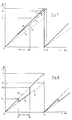
- a picture element A is shown schematically, as is usually used for displaying information on visual display devices.
- This picture element A has a width Ax and a height Ay. These two dimensions correspond, so that the picture element A is square and the width and height form the ratio 1: 1.
- An information element in the form of e.g. round pixel can be displayed.
- a picture element B is shown in dashed lines, which has a width Bx and a height By. If the width and height form the ratio 2: 3, then it is a picture element B, which is used for the information display on a screen text display device. In this case, e.g. elliptical pixel can be displayed.
- Fig. 2 shows an enlarged section of the screen of a data display device.
- This section contains 16 columns in the x direction and 16 rows of square picture elements in the y direction, which have the size of the picture element A shown in FIG. 1a and are shown with solid lines.
- This screen section could also contain 9 columns and 6 rows of such picture elements which correspond to picture element B shown in FIG. 1b.
- This arrangement of picture elements is shown in Fig. 2 by dashed lines, which are numbered accordingly.
- FIG. 2 in the lower right part of the screen section, a square with the side length Q is shown, which is composed of 6 rectangular picture elements a to f, each of which corresponds to picture element B according to FIG. 1b.
- This square would appear on a screen text display device as a representation of 6 screen text pixels, that is, would represent 6 information elements. If these information elements were displayed on a data display device, they would occupy a rectangle that is composed of square picture elements a 'to f' on the screen section in FIG. 2. From the different shape of the two areas occupied by 6 information elements on the screen section, it can be seen that when displaying screen text information on data display devices, a screen text object is reduced in size in the x and y directions, that is to say distorted.
- FIG. 2 an extension of the picture elements A of the data display device in the x direction and in the y direction must be provided , which corresponds to the differences in the dimensions of the picture elements A and B (FIG. 1).
- FIG. 2 can be seen that an object of the screen text, the top left corner of the x, y address 6.4 would appear shifted to the top left on a data display device if it were displayed with the same address but with picture elements of a data display device.
- Fig. 3 shows a type of change of the picture element A of a data display device, by means of which it is possible to display screen text information on a data display device not as true to area but as area-like, ie with similar distortion in the x and y directions, so that only the Scale, but not the form of information to be displayed changes.
- Fig. 3a shows a picture element which is composed of two picture elements A of the type shown in Fig. 1a, so that width and height form the ratio 1: 2.
- Fig. 3b shows a picture element A ', which has been created by widening the picture element according to Fig. 3a and has the width A'x and the height A'y.
- the invention provides the mapping of screen text information with picture elements of this type.
- a picture element A ' can be generated on a data display device in that the pixel in question is displayed twice over one another. The pixels of a picture line are therefore to be reproduced twice below one another. If each pixel then widened in the x direction is, a picture element is filled with the information of each pixel, which corresponds to the picture element A 'of Fig. 3b.
- FIG. 4 An image section of a visual display device is again shown, which has the size of the image section shown in FIG. 2 and contains the square with the side length Q, which consists of the picture elements a to f.
- the upper left corner of this square has the x, y address 6.4 in the dashed grid of picture elements which correspond to picture element B according to FIG. 1b.
- Fig. 4 shows another square with the side length Q ', the upper left corner in the solid line also has the x, y address 6.4 and consists of picture elements a ⁇ to f ⁇ , each of which in Fig. 3b shown picture element A 'correspond.
- Fig. 4 shows that when this principle is used, a screen text object is reproduced in a geometrically similar manner on a data display device, the shift to the top left being significantly less than according to Fig. 2 and a reduction taking place which is only recognizable when the screen size matches, however is also portable.
- FIG. 5 shows a circuit arrangement with which it is possible to optionally display normal data information or screen text information on a data display device.
- This circuit arrangement contains an image information memory 40, into which image information e.g. can be written from the working memory of a data processing device, not shown.
- This image information e.g. the intensity and the color of picture elements can be indicated, are passed via a data bus 42 from the picture information memory 40 to a converter 43, which converts them into analog red-green-blue signals for controlling a screen 44.
- the vertical and horizontal synchronization circuits required to display such information are not shown in FIG. 5. However, it should be assumed that the refresh rate and thus the vertical and horizontal synchronization frequency are constant regardless of the information to be displayed.
- a column counter 46 and a line counter 52 are used to address the image information memory 40.
- the column counter 46 thus addresses the image information memory 40 in the x direction, and the corresponding address signals are fed to it via an address bus 45. They are also fed via this address bus 45 to two comparators 47 and 48 which compare the respective current address with predetermined values X and X '.
- the two comparators 47 and 48 each give an output signal when the current address corresponds to the value X or X '. This output signal is fed via a changeover switch 49 to the reset input R of the column counter 46, the one contact of a changeover switch 51 and the clock input of a D flip-flop 50.
- the column counter 46 By connecting the output signal of the comparators 47 and 48 to the reset input R of the column counter 46, the maximum possible number of picture elements per line is determined in which 44 picture information is displayed on the screen can be displayed. After this maximum value has been reached, the column counter 46 begins its counting process starting from the count value zero. This counting process is controlled with a frequency f1, which is fed to the clock input of the column counter 46 via a changeover switch 57.
- the changeover switch 57 like the changeover switches 49 and 51, is controlled by a control signal U which is supplied to them by the data processing device, not shown.
- the D flip-flop 50 is connected as a factor of two because its data input is connected to its inverting output Q. The signals fed to him at the clock input thus appear at the other contact of the switch 51 with half the frequency.
- the changeover switch 51 is connected to the clock input of the line counter 52, so that it is clocked with the output signals of the D flip-flop 50 when the changeover switch 51 is in the appropriate position. This means that it increases its count by the value 1 every or every second reset of the column counter 46, which depends on the position of the switch 51.
- the output of the line counter 52 like the output of the column counter 46, is connected via an address bus 53 to the image information memory 40 and two comparators 54 and 55.
- the image information memory 40 is addressed in the y direction, the line counter 52 being reset each time the comparator 54 signals that the number of lines Y has been reached or that the comparator 55 signals that the number of lines Y 'has been reached and this signal is sent via a switch 56 to the Reset input of the line counter 52 outputs.
- the switch 56 is also controlled by the control signal U from the data processing device, not shown.
- the switches 49, 51, 56 and 57 must be brought into their second position, for which the control signal U is used. In this position, the readout speed is determined by the frequency f2, which forms the ratio 3: 4 with the frequency f1. It therefore leads to a slower reading of the image information and thus to its extension in the x direction by a factor of 4/3 compared to the previous representation. The readout speed in the y direction is reduced by a factor of 2 by the D flip-flop 50. Since, according to the prerequisite, the horizontal and vertical synchronization of the screen 44 should be constant, the image information of one line is reproduced again in the next line by the switchover.
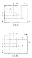
- the two comparators 48 and 55 determine the resetting of the column counter 46 and the row counter 52 each when the count X 'and Y' is reached. The size of these values must be explained below with reference to FIG. 6.
- the counting volumes 615 and 308 result from the fact that the picture elements of the screen 44 as required by a factor of 4/3 in are widened in the x direction and should assume twice the height in the y direction. Then the screen 44 can only take 615 image elements in the x direction and 308 image elements in the y direction. However, since the screen text information is displayed in accordance with the standard with 480 pixels in the x direction and 240 lines in the y direction, the screen 44 of the data display device cannot be used completely to display a screen text image. The unused area is shown hatched in FIG. 6b.
- the image information store 40 should also have predetermined information for the hatched area, e.g. a constant color reproduction, since the reading of information is basically not interrupted during the addressing of the image information memory 40.
- FIG. 7 shows a diagram of the time course of the addressing of the column counter 46 (FIG. 5) in the x direction.
- the curve 20 shows the increase in the count of the column counter 46 starting from zero to the final value X, which is reached at the time Ts.
- the dashed line 21 correspondingly shows the count of the column counter 46 starting from zero to the end value X ', which is also reached at time Ts.
- the slopes of the two curves 20 and 21 correspond to the timing of the column counter 46 with the frequency f1 or f2. After the time Ts, the counting process for the column counter 46 starts again from the zero count.
- the counting process must be slowed down during the time which corresponds to the width of the different picture part.
- a dash-dotted curve 22 is shown in FIG. 7, which illustrates that the column counter 46 is clocked more slowly during the time tx and, as the time tx elapses, reaches a lower count than in the normal curve 20. Starting from this lower count the column counter 46 is then clocked again faster.
- the dash-dotted curve 23 continued in FIG. 7, it can only reach the final position Xe at the time Ts.
- the column counter 46 When the counting process is continued, the column counter 46 only reaches the final value X corresponding to its counting volume at a later time Te, at which the scanning beam of the screen can already be in the next line.
- X-Xe which for the respective size within of a larger image to be displayed must be determined separately from the ratio tx: Ts in order to carry out a corresponding correction when addressing the image information memory 40 (FIG. 5).
- a more problematic is a correction of the displacement in the x-direction, which a pixel P, which would normally be shown at a certain point on the screen according to the course 20, experiences through the changed course 23.
- the pixel P is represented as the wrong pixel P 'at a later point in time, that is to say shifted in the x direction.
- Information with a column address that has a value greater than Xe can no longer be displayed.
- FIG. 8 shows the course of the addressing of two image information memories in the x-direction, which is composed of the individual courses 20 and 21 already shown in FIG. 7, so that a jump from course 20 into course 21 occurs during time tx results, which corresponds to section 24 of the overall curve.
- this section 24 is switched over and thus from one to the other image information memory, when the time tx has elapsed the system switches back to the first image information memory.
- a time window or an area is opened when displayed on the screen of a visual display device, on which another image with image elements A '(FIG. 1a) within an image with image elements A (FIG. 1a) (FIG. 3b) can be represented.
- Such a representation is shown in Fig. 9a.
- This representation corresponds to that according to Fig. 6b, i.e.
- a complete image 31 could be reproduced on the image area 30 of a data display device, e.g. is a screen text image.
- a part 32 of this screen text image is now mapped within the limits determined by the counter readings Xa, Xb, Ya and Yb described.
- FIG. 9a Another part 33 of the screen text image is indicated by dash-dotted lines in FIG. 9a. If this partial image 33 is to be displayed at the location of the screen area 30 at which the partial image 32 is also displayed, this can be achieved by shifting the entire screen text image 31, as shown in FIG. 9b. This shift results from the offset of the zero points of those counters which address the image information memory containing the screen text image. If the corresponding column counter is reset with a delay of Xr, the respective first pixel of a row is read from the image information memory with a corresponding delay. At this time, however, the scanning beam is at a position corresponding to the address Xr shown in Fig. 9b. A corresponding shift in the y direction can be provided with the amount Yr.
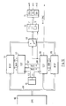
- FIG. 10 shows a circuit arrangement which enables the mode of operation according to FIGS. 8 and 9 and works with two image information memories.
- a data processing device 60 supplies, via an address data bus 61, image information which is to be reproduced with picture elements A '(FIG. 3b) into a first image information memory 62.
- the image information memory 62 is addressed by a column row counter 63 in the x and y directions .
- the clock input of the column line counter 63 is controlled by a clock generator 64, which supplies the clock frequency f2.
- the column row counter 66 synchronizes the column row counter 63 via two outputs 67 and 68 in the x and y directions.
- the output signals of the two image information memories 62 and 65 are fed via a changeover switch 69 to a color table memory 70, which in each case contains a conversion table 71 or 72 for the image information from the image information memory 62 or 65. This converts the image information into digital values for the individual colors red, green and implemented in blue. These values are then fed to a digital / analog conversion circuit 73, which converts the digital values for each color into corresponding analog values. These signals are then fed to the screen. Furthermore, a horizontal-vertical synchronization signal is supplied to the screen, which is emitted by the column row counter 66.
- the column row counter 66 also controls the changeover switch 69 and the color table memory 70.
- This changeover has the advantage that a common memory device and a common digital / analog converter circuit can be used for both color tables 71 and 72.
- the column line counter 63 is shown in the upper part of the figure, and the column line counter 66 is shown in the lower part.
- the column row counter 63 contains a first column counter 75, the clock input of which is controlled by the clock signals of the frequency f2.
- the output signals of the first column counter 75 are fed to a comparator 76 and to the image information memory 62. If the output signals correspond to a predetermined count X ', the comparator 76 outputs a reset signal via an OR gate 77 to the reset input of the column counter 75.
- the OR gate 77 is also driven with the x synchronization signal from the column row counter 66.
- the output of the comparator 76 is connected to a D flip-flop 78, which is connected as a factor of two. Its inverting output Q is connected to the clock input of a first line counter 79. Like the column counter 75, this is connected to a comparator 80 which, when a predetermined count Y 'is reached, outputs an output signal via an OR gate 81 to the reset input of the line counter 79. The output signals of the line counter 79 are also output to the image information memory 62.
- the OR gate 81 is driven at its second input by the y synchronization signal from the column row counter 66.
- the column row counter 66 contains a second column counter 85, the clock input of which is supplied with the clock signals with the frequency f1.
- the output of the column counter 85 is connected to the image information memory 65 and to the first inputs of comparators 86, 87, 88, 89.
- the comparators 87, 88, 89 are connected at their second inputs to the address data bus 61 and receive the values Xr, Xa and Xb via them (FIGS. 8, 9).
- the comparison value X of the comparator 86 is fixed.
- the output of this comparator 86 is connected to the reset input of the column counter 85 and to the clock input of a second row counter 90.
- the output of the comparator 87 provides the x synchronization signal.
- the outputs of the comparators 88 and 89 are connected to the two inputs of an AND gate 91, the output of which controls the one input of a further AND gate 92.
- the output of the line counter 90 is connected to the inputs of comparators 93, 94, 95, 96. These comparators are connected similarly to the comparators 86, 87, 88, 89 and are used to derive the corresponding y signals and the second input signal for the AND gate 92 via one AND gate 97.
- the comparators 94, 95, 96 also receive their second input signals via the address data bus 61.
- the output of the line counter 90 supplies its signals for the y direction to the image information memory 65.
- the AND gate 92 supplies the control signal for the changeover switch 69 and the color table memory 70.
- the operation of the column row counter 63 can be understood on the basis of the functional description of the circuit arrangement shown in FIG. 5. The same applies to the mode of operation of column row counter 66 insofar as column counter 85 with comparator 86 and row counter 90 with comparator 93 are concerned.
- the interaction of the two column row counters 63 and 66 corresponds to the procedure described with reference to FIGS. 8 and 9.
- the column counter 85 reaches the count X, it is reset.
- the x synchronization signal is output to the column row counter 63 and its column counter 75 is reset. If the count is between the values Xa and Xb, the comparators 88 and 89 deliver a logic 1 signal, and the AND gate 91 is switched through.
Description
Die Erfindung betrifft eine Schaltungsanordnung nach dem Oberbegriff des Patentanspruchs 1.The invention relates to a circuit arrangement according to the preamble of
Datensichtgeräte haben eine Bildschirmfläche, deren Seitenverhältnis im allgemeinen 4:3 beträgt. Da die Bildelementauflösung diesem Seitenverhältnis entspricht, hat jede auf dem Bildschirm dargestellte Bildelementinformation in x- und in y-Richtung übereinstimmende Seitenlänge bzw. Ausdehnung. Somit ist in dem zugehörigen Bildinformationsspeicher ein abbildungsgetreues Muster der Bildinformationselemente gespeichert. Durch die damit quadratische Form der Bildelemente ist es möglich, elektronisch in dem Bildinformationsspeicher den Speicherinhalt derart zu manipulieren, daß auf dem Bildschirm z.B. Drehbewegungen von Figuren verzerrungsfrei dargestellt werden können.Data display devices have a screen area, the aspect ratio of which is generally 4: 3. Since the picture element resolution corresponds to this aspect ratio, each picture element information displayed on the screen has the same side length or extension in the x and y directions. A true-to-image pattern of the image information elements is thus stored in the associated image information memory. The square shape of the picture elements makes it possible to electronically manipulate the memory content in the picture information memory in such a way that e.g. Rotational movements of figures can be displayed without distortion.
Informationen können bildlich aber auch mit Bildelementen dargestellt werden, die von der vorstehend beschriebenen Norm der Datensichtgeräte abweichen. Ein Beispiel dafür ist das Bildschirmtextverfahren. Bei diesem Verfahren werden Bildelemente verwendet, die das Seitenverhältnis 3:2 haben, also rechteckförmig sind. Die Bildinformationselemente haben bei der Darstellung auf der Fläche dieser Bildelemente dann nicht die Form eines kreisrunden Punktes, sondern einer Ellipse. Wird nach dem Bildschirmtextverfahren eine quadratische Fläche dargestellt, so besteht diese nicht aus gleich vielen Bildinformationselementen in x- und y-Richtung, sondern bei z.B. 30 Bildinformationselementen in x-Richtung beträgt deren Zahl in y-Richtung 20.Information can also be represented graphically with image elements that deviate from the above-described standard of data display devices. An example of this is the screen text method. In this method, picture elements are used which have an aspect ratio of 3: 2, that is to say are rectangular. When displayed on the surface of these picture elements, the picture information elements then do not have the shape of a circular point, but an ellipse. If a square area is displayed using the screen text method, it does not consist of the same Many image information elements in the x and y directions, but with, for example, 30 image information elements in the x direction, their number in the y direction is 20.
Wird ein solches Bildschirmtext-Bild auf dem Bildschirm eines normalen Datensichtgeräts dargestellt, so tritt eine Bildverzerrung ein, die dazu führt, daß ein Quadrat als Rechteck mit einem Seitenverhältnis dargestellt wird, das den kreisrunden Bildpunkten bzw. den durch die andere Rasterung quadratischen Darstellungsflächen der Bildelemente entspricht. Diese Verzerrung wirkt sich bei der Darstellung alphanumerischer Zeichen kaum auf deren Lesbarkeit aus, jedoch ist bei der Darstellung geometrischer Figuren eine Verfälschung des Informationsinhaltes gegeben, denn alle Informationen werden in y-Richtung stärker als in x-Richtung zusammengedrückt erscheinen.If such a screen text image is displayed on the screen of a normal visual display device, image distortion occurs, which leads to the fact that a square is represented as a rectangle with an aspect ratio that corresponds to the circular pixels or the display surfaces of the picture elements that are square due to the other rasterization corresponds. This distortion has little effect on the legibility of the representation of alphanumeric characters, however, the representation of the information content is falsified when displaying geometric figures, because all information will appear more compressed in the y direction than in the x direction.
Aus der GB-A-2 085 257 ist eine Schaltungsanordnung und ein Verfahren zum Ändern des Bildformates eines zeilenweise arbeitenden Bildschirmgeräts bekannt. Das Auslesen von Bildpunktdaten aus dem Bildinformationsspeicher wird mittels einer phasenstarren Regelschleife gesteuert. Aufgrund der Phasenstarrheit kann es beim Umschalten vorübergehend zu Bildstörungen auf dem Bildschirm kommen, bis die Regelschleife eingerastet ist. Zum Ändern des Bildformats wird bei der bekannten Schaltungsanordnung eine Zeilenverdoppelung durchgeführt, wozu zwischen einem Zeilenzähler und dem Bildinformationsspeicher ein Selektor geschaltet wird. Dieser Selektor halbiert die Adresse der Bildpunkte durch Bitverschiebung über Multiplexer oder Festwertspeicher.GB-A-2 085 257 discloses a circuit arrangement and a method for changing the picture format of a display device operating line by line. The reading out of pixel data from the image information memory is controlled by means of a phase-locked loop. Due to the phase rigidity, there may be temporary image disturbances on the screen when switching, until the control loop has engaged. To change the picture format, a line doubling is carried out in the known circuit arrangement, for which purpose a selector is connected between a line counter and the picture information memory. This selector halves the address of the pixels by bit shifting via multiplexer or read-only memory.
Es ist Aufgabe der Erfindung, auf einem Datensichtgerät die Darstellung von Informationen mit Bildelementen unterschiedlicher Seitenverhältnisse zu ermöglichen, so daß keine Informationsverfälschung stattfindet.It is an object of the invention to display information with picture elements on a visual display device to enable different aspect ratios so that there is no falsification of information.
Diese Aufgabe wird durch die Merkmale des Patentanspruchs 1 gelöst.This object is achieved by the features of
Durch die Erfindung wird erreicht, daß Informationen, deren Darstellung für Bildelemente mit dem abweichenden Seitenverhältnis vorgesehen ist, auch auf einem Datensichtge rät dargestellt werden können, dessen Bildelemente das übliche Seitenverhältnis 1:1 haben. Die Informationen werden dabei zwar nicht flächengetreu wiedergegeben, jedoch geometrisch ähnlich, d.h. ein Quadrat wird als Quadrat und ein Kreis als Kreis wiedergegeben. Es tritt zwar eine Größenveränderung derartiger Figuren ein, jedoch fällt diese kaum ins Gewicht und wird nur bei Vergleich mit einem gleich großen Bildschirm der anderen Darstellungsart erkennbar.It is achieved by the invention that information, the representation of which is provided for picture elements with the different aspect ratio, also on a data view advises can be displayed, the picture elements have the usual aspect ratio 1: 1. The information is not reproduced true to area, but is geometrically similar, ie a square is represented as a square and a circle as a circle. Although there is a change in the size of such figures, this is hardly significant and is only recognizable when compared with an equally large screen of the other display type.
Die Erfindung kann auf praktische alle Fälle abweichender Seitenverhältnisse angewendet werden und ist mit geringem zusätzlichem Aufwand an Schaltmitteln realisierbar. Eine Änderung der Auslesegeschwindigkeit des Bildinformationsspeichers kann nur für die x-Richtung oder nur für die y-Richtung oder für beide Richtungen vorgesehen sein, was davon abhängt, für welche Richtung die Entzerrung durchzuführen ist. Die Änderung der Auslesegeschwindigkeit kann in einer Verringerung oder Erhöhung bestehen, jedoch wird in den meisten Fällen die Verringerung zweckmäßig sein, weil dem Auflösungsvermögen der Datensichtgeräte Grenzen gesetzt sind, die eine beliebige Verkleinerung der Bildpunkte verhindern. Wird die Auslesegeschwindigkeit verringert, so kann dies für die y-Richtung sehr einfach dadurch geschehen, daß jede Zeile von Bildelementinformationen aus dem Bildinformationsspeicher mehrfach nacheinander ausgelesen wird. Die Bildelemente und damit auch die Bildpunkte werden dadurch in y-Richtung jeweils um eine oder mehrere Zeilendicken verlängert.The invention can be applied to practically all cases of different aspect ratios and can be implemented with little additional outlay on switching means. A change in the readout speed of the image information memory can only be provided for the x direction or only for the y direction or for both directions, which depends on the direction for which the equalization is to be carried out. The change in the readout speed can consist of a reduction or an increase, but in most cases the reduction will be expedient because the resolution of the data display devices is limited, which prevents any reduction in the pixels. If the readout speed is reduced, this can be done very simply for the y direction by reading out each line of picture element information from the picture information memory several times in succession. The picture elements and thus also the picture elements are thereby extended in the y-direction by one or more line thicknesses.
Die folgende Beschreibung erläutert vorteilhafte Weiterbildungen der Erfindung, die in den Unteransprüchen angegeben sind und für beliebige Abweichungen der Seitenverhältnisse zweier unterschiedlicher Darstellungsarten anwendbar sind. Hierbei wird auf die Zeichnung Bezug genommen. Darin zeigen:
- Fig. 1a und 1b
- zwei Bildelemente mit unterschiedlichen Seitenverhältnissen,
- Fig. 2
- eine Darstellung von Informationen mit Bildelementen unterschiedlicher Seitenverhältnisse auf eine und demselben Bildschirm,
- Fig. 3a und 3b
- weitere Bildelemente mit unterschiedlichen Seitenverhältnissen,
- Fig. 4
- eine Darstellung ähnlich Fig. 2, jedoch für die Anwendung der Erfindung,
- Fig. 5
- eine Ausführungsbeispiel einer Schaltungsanordnung nach der Erfindung,
- Fig. 6a und 6b
- schematische Darstellungen des Adressierprinzips eines Bildinformationsspeichers bei Anwendung der Erfindung auf Bildschirmtext-Darstellung mit einem Datensichtgerät,
- Fig. 7
- den Adressiervorgang in einer Schaltungsanordnung nach Fig. 5 für den Fall einer Bild im Bild-Darstellung,
- Fig. 8
- einen Adressiervorgang ähnlich Fig. 7, jedoch bei Anwendung einer Weiterbildung der Erfindung,
- Fig. 9a und 9b
- jeweils eine schematische Bild im Bild-Darstellung bei Anwendung der Erfindung,
- Fig. 10
- eine weiteres Ausführungsbeispiel einer Schaltungsanordnung nach der Erfindung und
- Fig. 11
- eine deutlichere Darstellung zweier in der Schaltungsanordnung nach Fig. 10 verwendeter Adressierschaltungen.
- 1a and 1b
- two picture elements with different aspect ratios,
- Fig. 2
- a representation of information with picture elements of different aspect ratios on one and the same screen,
- 3a and 3b
- further picture elements with different aspect ratios,
- Fig. 4
- a representation similar to FIG. 2, but for the application of the invention,
- Fig. 5
- an embodiment of a circuit arrangement according to the invention,
- 6a and 6b
- schematic representations of the addressing principle of an image information store when using the invention on screen text representation with a data display device,
- Fig. 7
- 5 for the case of a picture in picture representation,
- Fig. 8
- 7, but when using a development of the invention,
- 9a and 9b
- each a schematic image in the image representation when using the invention,
- Fig. 10
- a further embodiment of a circuit arrangement according to the invention and
- Fig. 11
- a clearer representation of two addressing circuits used in the circuit arrangement of FIG. 10.
In Fig. 1a ist schematisch ein Bildelement A dargestellt, wie es üblicherweise zur Informationsdarstellung auf Datensichtgeräten verwendet wird. Dieses Bildelement A hat eine Breite Ax und eine Höhe Ay. Diese beiden Abmessungen stimmen überein, so daß das Bildelement A quadratisch ist und Breite und Höhe das Verhältnis 1:1 bilden. Auf der quadratischen Darstellungsfläche des Bildelements A kann ein Informationselement in Form eines z.B. runden Bildpunktes dargestellt werden.In Fig. 1a, a picture element A is shown schematically, as is usually used for displaying information on visual display devices. This picture element A has a width Ax and a height Ay. These two dimensions correspond, so that the picture element A is square and the width and height form the ratio 1: 1. An information element in the form of e.g. round pixel can be displayed.
In Fig. 1b ist ein Bildelement B gestrichelt dargestellt, das eine Breite Bx und eine Höhe By hat. Wenn Breite und Höhe das Verhältnis 2:3 bilden, so handelt es sich um eine Bildelement B, das für die Informationsdarstellung auf einem Bildschirmtext-Sichtgerät verwendet wird. Dabei kann auf der Darstellungsfläche des Bildelements B ein z.B. ellipsenförmiger Bildpunkt dargestellt werden.In Fig. 1b, a picture element B is shown in dashed lines, which has a width Bx and a height By. If the width and height form the ratio 2: 3, then it is a picture element B, which is used for the information display on a screen text display device. In this case, e.g. elliptical pixel can be displayed.
Die vorstehend erläuterten Bildelemente A und B eines Datensichtgeräts und eines Bildschirmtext-Sichtgeräts stimmen weder in ihren Abmessungen noch in ihren Abmessungsverhältnissen überein.The above-described image elements A and B of a data display device and a screen text display device do not match either in their dimensions or in their dimensional relationships.
Fig. 2 zeigt einen vergrößerten Ausschnitt des Bildschirms eines Datensichtgeräts. Dieser Ausschnitt enthält in x-Richtung 16 Spalten und in y-Richtung 16 Zeilen quadratischer Bildelemente, die die Größe des in Fig. 1a gezeigten Bildelements A haben und mit durchgezogenen Linien dargestellt sind. Dieser Bildschirmausschnitt könnte auch 9 Spalten und 6 Zeilen solcher Bildelemente aufnehmen, die dem in Fig. 1b dargestellten Bildelement B entsprechen. Diese Anordnung von Bildelementen ist in Fig. 2 durch gestrichelte Linien dargestellt, die entsprechend numeriert sind.Fig. 2 shows an enlarged section of the screen of a data display device. This section contains 16 columns in the x direction and 16 rows of square picture elements in the y direction, which have the size of the picture element A shown in FIG. 1a and are shown with solid lines. This screen section could also contain 9 columns and 6 rows of such picture elements which correspond to picture element B shown in FIG. 1b. This arrangement of picture elements is shown in Fig. 2 by dashed lines, which are numbered accordingly.
In Fig. 2 ist im rechten unteren Teil des Bildschirmausschnittes ein Quadrat mit der Seitenlänge Q dargestellt, das aus 6 rechteckförmigen Bildelementen a bis f zusammengesetzt ist, die jeweils dem Bildelement B nach Fig. 1b entsprechen. Dieses Quadrat würde auf einem Bildschirmtext-Sichtgerät als Darstellung von 6 Bildschirmtext-Bildpunkten erscheinen, also 6 Informationselemente wiedergeben. Würden diese Informationselemente auf einem Datensichtgerät wiedergegeben, so würden sie ein Rechteck belegen, das auf dem Bildschirmausschnitt in Fig. 2 aus quadratischen Bildelementen a′ bis f′ zusammengesetzt ist. Aus der unterschiedlichen Form der beiden auf dem Bildschirmausschnitt mit 6 Informationselementen belegten Teilflächen ist zu erkennen, daß bei der Darstellung von Bildschirmtext-Informationen auf Datensichtgeräten ein Bildschirmtext-Objekt in x- und y-Richtung unterschiedlich verkleinert, also verzerrt wird. So können bei der Darstellung von Bildschirmtext-Informationen auf Datensichtgeräten beispielsweise aus Quadraten Rechtecke und aus Kreisen Ellipsen werden und Buchstaben in ihrer Höhe zusammengedrückt erscheinen. Bei alphanumerischen Texten führt eine solche Verzerrung im allgemeinen nicht zu einer Beeinträchtigung der Lesbarkeit. Bei geometrischen Figuren ist aber eine Veränderung der Informationen unvermeidbar.In FIG. 2, in the lower right part of the screen section, a square with the side length Q is shown, which is composed of 6 rectangular picture elements a to f, each of which corresponds to picture element B according to FIG. 1b. This square would appear on a screen text display device as a representation of 6 screen text pixels, that is, would represent 6 information elements. If these information elements were displayed on a data display device, they would occupy a rectangle that is composed of square picture elements a 'to f' on the screen section in FIG. 2. From the different shape of the two areas occupied by 6 information elements on the screen section, it can be seen that when displaying screen text information on data display devices, a screen text object is reduced in size in the x and y directions, that is to say distorted. For example, when displaying screen text information on visual display devices, squares can become rectangles and circles can be ellipses, and letters can appear compressed in their height. In the case of alphanumeric texts, such a distortion generally does not impair readability. In the case of geometric figures, however, a change in the information is unavoidable.
Wenn diese Verzerrungen vermieden werden sollen, also eine flächengetreue Darstellung der Bildinformationen des Bildschirmtextes auf einem Datensichtgerät vorzunehmen ist, so muß, wie aus Fig. 2 erkennbar wird, eine Verlängerung der Bildelemente A des Datensichtgeräts in x-Richtung und in y-Richtung vorgesehen werden, die den Unterschieden der Abmessungen der Bildelemente A und B (Fig. 1) entspricht. Außerdem kann Fig. 2 entnommen werden, daß ein Objekt des Bildschirmtextes, dessen linke obere Ecke die x,y-Adresse 6,4 hat, auf einem Datensichtgerät nach links oben verschoben erscheinen würde, wenn es mit derselben Adresse, aber mit Bildelementen eines Datensichtgeräts abgebildet würde.If these distortions are to be avoided, that is to say that the image information of the screen text is to be displayed in a true-to-area manner on a data display device, then, as can be seen from FIG. 2, an extension of the picture elements A of the data display device in the x direction and in the y direction must be provided , which corresponds to the differences in the dimensions of the picture elements A and B (FIG. 1). In addition, Fig. 2 can be seen that an object of the screen text, the top left corner of the x, y address 6.4 would appear shifted to the top left on a data display device if it were displayed with the same address but with picture elements of a data display device.
Wollte man bei einem Datensichtgerät die Höhe der Bildelemente in y-Richtung ändern, so müßten umfangreiche Änderungen vorgenommen werden, die zu einer von der Norm abweichenden Zeilenzahl führen würden. Ein Angleichen der Darstellung auf einem Datensichtgerät an diejenige eines Bildschirmtext-Sichtgeräts derart, daß Bildschirmtext-Informationen auf einem Datensichtgerät flächengetreu wiedergegeben werden, ist also nicht ohne weiteres möglich.If one wanted to change the height of the picture elements in the y direction with a data display device, extensive changes would have to be made which would lead to a number of lines deviating from the norm. An adjustment of the display on a data display device to that of a screen text display device in such a way that screen text information is reproduced area-wide on a data display device is therefore not readily possible.
Fig. 3 zeigt eine Art der Veränderung des Bildelements A eines Datensichtgeräts, durch die es möglich ist, Bildschirmtext-Informationen auf einem Datensichtgerät nicht flächengetreu,sondern flächenähnlich darzustellen, d.h. mit in x- und y-Richtung gleichartiger Verzerrung, so daß sich lediglich der Maßstab, nicht aber die Form wiederzugebender Informationen ändert. Fig. 3a zeigt ein Bildelement, das aus zwei Bildelementen A der in Fig. 1a gezeigten Art zusammengesetzt ist, so daß Breite und Höhe das Verhältnis 1:2 bilden. Fig. 3b zeigt ein Bildelement A′, das durch eine Verbreiterung des Bildelements nach Fig. 3a entstanden ist und die Breite A′x und die Höhe A′y hat. Die Erfindung sieht die Abbildung von Bildschirmtext-Informationen mit Bildelementen dieser Art vor. Da die Höhe A′y den doppelten Wert der Höhe Ay des Bildelements nach Fig.1a hat, kann ein Bildelement A′ auf einem Datensichtgerät dadurch erzeugt werden, daß der betreffende Bildpunkt zweimal übereinander dargestellt wird. Die Bildpunkte einer Bildzeile sind demgemäß zweimal untereinander wiederzugeben. Wenn jeder Bildpunkt dann noch in x-Richtung verbreitert wird, so wird mit der Information eines jeden Bildpunktes ein Bildelement ausgefüllt, das dem Bildelement A′ nach Fig. 3b entspricht.Fig. 3 shows a type of change of the picture element A of a data display device, by means of which it is possible to display screen text information on a data display device not as true to area but as area-like, ie with similar distortion in the x and y directions, so that only the Scale, but not the form of information to be displayed changes. Fig. 3a shows a picture element which is composed of two picture elements A of the type shown in Fig. 1a, so that width and height form the ratio 1: 2. Fig. 3b shows a picture element A ', which has been created by widening the picture element according to Fig. 3a and has the width A'x and the height A'y. The invention provides the mapping of screen text information with picture elements of this type. Since the height A'y has twice the value of the height Ay of the picture element according to Fig.1a, a picture element A 'can be generated on a data display device in that the pixel in question is displayed twice over one another. The pixels of a picture line are therefore to be reproduced twice below one another. If each pixel then widened in the x direction is, a picture element is filled with the information of each pixel, which corresponds to the picture element A 'of Fig. 3b.
Das Ergebnis einer solchen Darstellung zeigt Fig. 4. Es ist wiederum ein Bildausschnitt eines Datensichtgeräts gezeigt, der die Größe des in Fig. 2 gezeigten Bildausschnittes hat und das Quadrat mit der Seitenlänge Q enthält, welches aus den Bildelementen a bis f besteht. Die linke obere Ecke dieses Quadrats hat die x,y-Adresse 6,4 in dem gestrichelt dargestellten Raster von Bildelementen, die dem Bildelement B nach Fig. 1b entsprechen. Fig. 4 zeigt ein weiteres Quadrat mit der Seitenlänge Q′, dessen linke obere Ecke in dem durchgezogen dargestellten Raster gleichfalls die x,y-Adresse 6,4 hat und aus Bildelementen a˝ bis f˝ besteht, die jeweils dem in Fig. 3b gezeigten Bildelement A′ entsprechen. Die Quadratform der mit diesen Bildelementen a˝ bis f˝ wiedergegebenen Figur ergibt sich dan, wenn Breite und Höhe des Bildelements A′ nach Fig. 3b das Verhältnis 2:3 bilden, da dieses auch für das Bildelement B nach Fig. 1b vorausgesetzt wird. Es ist leicht zu erkennen, daß dieses Verhältnis vorliegt, wenn ![]()
![]()
![]()
![]()
The result of such an illustration is shown in FIG. 4. An image section of a visual display device is again shown, which has the size of the image section shown in FIG. 2 and contains the square with the side length Q, which consists of the picture elements a to f. The upper left corner of this square has the x, y address 6.4 in the dashed grid of picture elements which correspond to picture element B according to FIG. 1b. Fig. 4 shows another square with the side length Q ', the upper left corner in the solid line also has the x, y address 6.4 and consists of picture elements a˝ to f˝, each of which in Fig. 3b shown picture element A 'correspond. The square shape of the figure reproduced with these picture elements a˝ to f˝ is obtained if the width and height of the picture element A 'according to FIG. 3b form the ratio 2: 3, since this is also assumed for the picture element B according to FIG. 1b. It is easy to see that this relationship exists when ![]()
![]()
![]()
![]()
Fig. 4 zeigt, daß bei Anwendung dieses Prinzips ein Bildschirmtext-Objekt auf einem Datensichtgerät geometrisch ähnlich wiedergegeben wird, wobei die Verschiebung nach links oben wesentlich geringer als nach Fig. 2 ist und eine Verkleinerung erfolgt, die nur bei übereinstimmender Bildschirmgröße erkennbar wird, jedoch auch dann tragbar ist.Fig. 4 shows that when this principle is used, a screen text object is reproduced in a geometrically similar manner on a data display device, the shift to the top left being significantly less than according to Fig. 2 and a reduction taking place which is only recognizable when the screen size matches, however is also portable.
In Fig. 5 ist eine Schaltungsanordnung dargestellt, mit der es möglich ist, auf einem Datensichtgerät wahlweise normale Dateninformationen oder Bildschirmtext-Informationen darzustellen. Diese Schaltungsanordnung enthält einen Bildinformationsspeicher 40, in den über einen Adreß-Datenbus 41 Bildinformationen z.B. aus dem Arbeitsspeicher einer nicht gezeigten Datenverarbeitungseinrichtung eingeschrieben werden. Diese Bildinformationen, die z.B. die Intensität und die Farbe von Bildelementen angeben können, werden über einen Datenbus 42 aus dem Bildinformationsspeicher 40 zu einem Umsetzer 43 geleitet, der sie in analoge rot-grünblau-Signale zur Ansteuerung eines Bildschirms 44 umsetzt. Die zur bildlichen Darstellung solcher Informationen erforderlichen Vertikal- und Horizontalsynchronisationsschaltungen sind in Fig. 5 nicht gezeigt. Es sei aber vorausgesetzt, daß die Bildwiederholfrequenz und damit die Vertikal- und Horizontalsynchronisationsfrequenz unabhängig von den darzustellenden Informationen konstant sind.5 shows a circuit arrangement with which it is possible to optionally display normal data information or screen text information on a data display device. This circuit arrangement contains an
Zur Adressierung des Bildinformationsspeichers 40 dienen ein Spaltenzähler 46 und ein Zeilenzähler 52. Der Spaltenzähler 46 adressiert den Bildinformationsspeicher 40 also in x-Richtung, und die entsprechenden Adressensignale werden ihm über einen Adreßbus 45 zugeführt. Sie werden über diesen Adreßbus 45 ferner zwei Vergleichern 47 und 48 zugeführt, die die jeweils aktuelle Adresse mit vorgegebenen Werten X bzw. X′ vergleichen. Die beiden Vergleicher 47 und 48 geben jeweils ein Ausgangssignal ab, wenn die aktuelle Adresse mit dem Wert X bzw. X′ übereinstimmt. Dieses Ausgangssignal wird über einen Umschalter 49 dem Rücksetzeingang R des Spaltenzählers 46, dem einen Kontakt eines Umschalters 51 und dem Takteingang eines D-Flipflops 50 zugeführt. Durch die Verbindung des Ausgangssignals der Vergleicher 47 und 48 mit dem Rücksetzeingang R des Spaltenzählers 46 wird die maximal mögliche Zahl Bildelemente pro Zeile bestimmt, in denen auf dem Bildschirm 44 Bildinformationen dargestellt werden können. Nach Erreichen dieses Maximalwertes beginnt der Spaltenzähler 46 seinen Zählvorgang ausgehend vom Zählwert Null. Dieser Zählvorgang wird mit einer Frequenz f1 gesteuert, die dem Takteingang des Spaltenzählers 46 über einen Umschalter 57 zugeführt wird. Der Umschalter 57 wird wie die Umschalter 49 und 51 durch ein Steuersignal U gesteuert, das ihnen von der nicht gezeigten Datenverarbeitungseinrichtung zugeführt wird.A
Das D-Flipflop 50 ist als Faktor 2-Teiler geschaltet, da sein Dateneingang mit seinem invertierenden Ausgang Q verbunden ist. Die ihm am Takteingang zugeführten Signale erscheinen also am anderen Kontakt des Umschalters 51 mit halber Frequenz. Der Umschalter 51 ist mit dem Takteingang des Zeilenzählers 52 verbunden, so daß dieser bei entsprechender Position des Umschalters 51 mit den Ausgangssignalen des D-Flipflops 50 getaktet wird. Dies bedeutet, daß er seinen Zählstand bei jedem oder bei jedem zweiten Rücksetzen des Spaltenzählers 46 um den Wert 1 erhöht, was von der Position des Umschalters 51 abhängt. Der Ausgang des Zeilenzählers 52 ist wie der Ausgang des Spaltenzählers 46 über einen Adreßbus 53 mit dem Bildinformationsspeicher 40 und zwei Vergleichern 54 und 55 verbunden. Dadurch wird der Bildinformationsspeicher 40 in y-Richtung adressiert, wobei der Zeilenzähler 52 jeweils dann rückgesetzt wird, wenn der Vergleicher 54 das Erreichen der Zeilenzahl Y bzw. der Vergleicher 55 das Erreichen der Zeilenzahl Y′ signalisiert und dieses Signal über einen Umschalter 56 an den Rücksetzeingang des Zeilenzählers 52 abgibt. Der Umschalter 56 wird gleichfalls durch das Steuersignal U aus der nicht gezeigten Datenverarbeitungseinrichtung gesteuert.The D flip-
In der in Fig. 5 gezeigten Position der Umschalter 49, 51 56 und 57 wird der Inhalt des Bildinformationsspeichers 40 auf dem Bildschirm 44 in Bildelementen abgebildet, deren Raster demjenigen eines normalen Datensichtgeräts entspricht. Dabei wird die Auslesegeschwindigkeit in x-Richttung durch die Frequenz f1 bestimmt und mit jedem Rücksetzen des Spaltenzählers 46 zur nächsten Zeile weitergeschaltet. Die letzte Spalte bzw. Zeile ist durch die Vergleicher 47 und 54 bestimmt, die den Zählstand X bzw. Y signalisieren.In the position of the
Wenn der Bildinformationsspeicher 40 Bildinformationen enthält, die in Bildelementen darzustellen sind, welche von der Größe der Bildelemente eines normalen Datensichtgeräts abweichen, so müssen die Umschalter 49, 51, 56 und 57 in ihre zweite Position gebracht werden, wozu das Steuersignal U dient. In dieser Stellung wird die Auslesegeschwindigkeit durch die Frequenz f2 bestimmt, die mit der Frequenz f1 das Verhältnis 3:4 bildet. Sie führt also zu einem langsameren Auslesen der Bildinformationen und damit zu deren Verlängerung in x-Richtung mit dem Faktor 4/3 gegenüber der vorherigen Darstellung. Die Auslesegeschwindigkeit in y-Richtung wird durch das D-Flipflop 50 um den Faktor 2 reduziert. Da gemäß Voraussetzung die Horizontal- und die Vertikalsynchronisation des Bildschirms 44 konstant sein sollen, werden durch die Umschaltung die Bildinformationen einer Zeile in der nächstfolgenden Zeile erneut wiedergegeben. Die beiden Vergleicher 48 und 55 bestimmen dabei das Rücksetzen des Spaltenzähler 46 und des Zeilenzählers 52 jeweils bei Erreichen des Zählstandes X′ und Y′. Wie groß diese Werte sein müssen, wird im folgenden an Hand der Fig. 6 erläutert.If the
In Fig. 6a sind die Zählvolumina des Spaltenzählers 46 (Fig.5) und des Zeilenzählers 52 (Fig. 5) als Diagramm dargestellt für den Fall der Informationsdarstellung auf dem Bildschirm 44 mit quadratischen Bildelementen, deren Anzahl pro Zeile 820 ist und wobei die Zeilenzahl 615 beträgt. Einschließlich des Zählstandes Null wird der Spaltenzähler 46 also bei Erreichen des Zählstandes X = 819 und der Zeilenzähler 52 bei Erreichen des Zählstandes Y = 614 rückgesetzt. Das in Fig. 6a gezeigte Diagramm gibt also nicht nur die Zählvolumina in x- und y-Richtung wieder, sondern auch Vielfache der Taktzeit ![]()
![]()
Wenn auf dem Bildschirm nicht quadratische,sondern rechteckförmige Bildelemente zur Informationsdarstellung verwendet werden sollen und diese dem in Fig. 3b dargestellten Bildelement A′ entsprechen und wenn ferner diese Informationsdarstellung aus Bildschirmtext-Informationen besteht, so ergibt sich das in Fig. 6b gezeigte Diagramm, das für den Spaltenzähler 46 das Zählvolumen 615 und für den Zeilenzähler 52 das Zählvolumen 308 wiedergibt. Dies entspricht in x-Richtung einer Taktzeit ![]()
![]()
Das Diagramm nach Fig. 6b entspricht auch der tatsächlichen Bildwiedergabe des Bildschirmtext-Objekts, wenn der Abtaststrahl des Bildschirms 44 für die x,y-Adresse 0,0 des Bildschirmtext-Bildes im Bildschirm 44 auch die Position 0,0 hat. Ist dies nicht der Fall, so kann der schraffierte Bereich auch an anderer Stelle erscheinen, d.h. die in Fig. 6b gezeigte weiße Bildfläche hat dann eine andere Lage. Der Bildinformationsspeicher 40 sollte auch für den schraffierten Bereich vorbestimmte Informationen, z.B. eine gleichbleibende Farbwiedergabe, enthalten, da das Lesen von Informationen während der Adressierung des Bildinformationsspeichers 40 grundsätzlich nicht unterbrochen wird.6b also corresponds to the actual image reproduction of the screen text object if the scanning beam of the
Vorstehend wurde vorausgesetzt, daß mit der in Fig. 5 gezeigten Schaltungsanordnung entweder eine Informationsdarstellung mit Bildelementen A der in Fig. 1a gezeigten Art oder mit Bildelementen A′ der in Fig. 3b gezeigten Art gesteuert werden soll. Dies ist mit der in Fig. 5 gezeigten Schaltungsanordnung problemlos, wenn es sich um die Belegung des gesamten Bildschirms entweder mit der einen oder mit der anderen Art von Informationen handelt. Soll aber eine Bild im Bild-Darstellung mit Bildelementen unterschiedlicher Abmessung in x- und y-Richtung durchgeführt werden, wie sie in Fig. 4 für das Quadrat mit der Seitenlänge Q′ in dem größeren Bildausschnitt gezeigt ist, so können bei Anwendung der in Fig. 5 gezeigten Schaltungsanordnung Effekte auftreten, die nur mit erhöhtem schaltungstechnischem Aufwand zu vermeiden sind. Zur Erläuterung wird nun auf Fig. 7 Bezug genommen, die ein Diagramm des zeitlichen Verlaufs der Adressierung des Spaltenzählers 46 (Fig. 5) in x-Richtung zeigt. Der Verlauf 20 zeigt die Zunahme des Zählstandes des Spaltenzählers 46 ausgehend von Null bis zum Endstand X, der zum Zeitpunkt Ts erreicht wird. Der gestrichelt dargestellte Verlauf 21 zeigt entsprechend den Zählstand des Spaltenzählers 46 ausgehend von Null bis zum Endwert X′, der gleichfalls zum Zeitpunkt Ts erreicht wird. Die Steigungen der beiden Verläufe 20 und 21 entsprechen der Taktung des Spaltenzählers 46 mit der Frequenz f1 oder f2. Nach dem Zeitpunkt Ts beginnt der Zählvorgang für den Spaltenzähler 46 wieder ausgehend vom Zählstand Null. Wenn ein Teil der Bildschirmfläche Informationen mit Bildelementen darstellen soll, die breiter als die im übrigen Teil der Bildfläche verwendeten Bildelemente sind, so muß der Zählvorgang während der Zeit, die der Breite des unterschiedlichen Bildteils entspricht, verlangsamt werden. Für diese Zeit tx ist in Fig. 7 ein strichpunktierter Verlauf 22 dargestellt, der verdeutlicht, daß der Spaltenzähler 46 während der Zeit tx langsamer getaktet wird und mit Ablauf der Zeit tx einen geringeren Zählstand erreicht als bei normalem Verlauf 20. Ausgehend von diesem geringeren Zählstand wird der Spaltenzähler 46 dann wieder schneller getaktet. Er kann aber entsprechend dem in Fig. 7 fortgesetzten strichpunktierten Verlauf 23 zum Zeitpunkt Ts nur den Endstand Xe erreichen. Bei Fortsetzung des Zählvorgans erreicht der Spaltenzähler 46 den seinem Zählvolumen entsprechenden Endstand X erst zu einem späteren Zeitpunkt Te, zu dem sich der Abtaststrahl des Bildschirms bereits in der nächstfolgenden Zeile befinden kann. Es ergibt sich eine Differenz X-Xe, die für die jeweilige Größe eines innerhalb eines größeren Bildes darzustellenden Bildausschnittes gesondert aus dem Verhältnis tx:Ts bestimmt werden muß, um bei der Adressierung des Bildinformationsspeichers 40 (Fig.5) eine entsprechende Korrektur durchzuführen. Problematischer ist eine Korrektur der Verschiebung in x-Richtung, die ein Bildpunkt P, der gemäß dem Verlauf 20 normalerweise an einer bestimmten Stelle des Bildschirms abgebildet würde, durch den geänderten Verlauf 23 erfährt. Dadurch wird der Bildpunkt P als falscher Bildpunkt P′ zu einem späteren Zeitpunkt, also in x-Richtung verschoben, dargestellt. Informationen mit einer Spaltenadresse, die einen Wert größer als Xe hat, können nicht mehr dargestellt werden.Above it was assumed that with the circuit arrangement shown in Fig. 5 either an information display with picture elements A of the type shown in Fig. 1a or with picture elements A 'of the type shown in Fig. 3b is to be controlled. This is problem-free with the circuit arrangement shown in FIG. 5 when it is a question of occupying the entire screen with either one or the other type of information. If, however, an image is to be carried out in the image display with image elements of different dimensions in the x and y directions, as shown in FIG. 4 for the square with the side length Q 'in the larger image section, then at Applying the circuit arrangement shown in FIG. 5, effects occur which can only be avoided with increased circuitry complexity. For explanation, reference is now made to FIG. 7, which shows a diagram of the time course of the addressing of the column counter 46 (FIG. 5) in the x direction. The
Probleme ähnlich den vorstehend beschriebenen treten auch hinsichtlich der Adressierung des Bildinformationsspeichers 40 in y-Richtung auf.Problems similar to those described above also occur with regard to the addressing of the
Umfangreiche Zusatzschaltungen, die entsprechende Korrekturen vornehmen, können vermieden werden, wenn zwei getrennte Bildinformationsspeicher für Bildelemente A einerseits und für Bildelemente A′ andererseits verwendert werden. Dabei kann dann der eine Bildinformationsspeicher gemäß dem in Fig. 7 gezeigten Verlauf 20 und der andere Bildinformationsspeicher gemäß dem in Fig. 7 gezeigten Verlauf 21 in x-Richtung und in y-Richtung entsprechend adressiert werden. Damit bei Verwendung zweier Bildinformationsspeicher mit getrennter Spalten- und Zeilenadressierung eine feststehende Bild im Bild-Darstellung erhalten wird, müssen die Adressierungen beider Bildinformationsspeicher dieselbe Bildwiederholfrequenz haben. Dies wird einfach dadurch erreicht, daß die Taktfrequenzen beider Spaltenzähler aus derselben Quelle abgeleitet werden und die Endwerte der Spaltenzähler den an Hand der Fig. 6 beschriebenen Bedingungen genügen. Es ist ferner sinnvoll, den Spaltenzähler und den Zeilenzähler des einen Bildinformationsspeichers mit dem Spalten- bzw. Zeilenzähler des anderen Bildinformationsspeichers zu synchronisieren, um die Nullpunkte aller Zähler zeitlich fest miteinander zu verbinden. Anderenfalls würden die Zähler jeweils zwar in übereinstimmender Zeit immer wider denselben Zählstand erreichen, jedoch wäre der zum jeweiligen Zeitpunkt erreichte absolute Zählstand durch unbestimmte Zustände im Einschaltmoment der Schaltungsanordnung bestimmt.Extensive additional circuits that make appropriate corrections can be avoided if two separate image information memories for image elements A on the one hand and for image elements A 'on the other hand are used. In this case, one image information store according to the
In Fig. 8 ist der Verlauf der Adressierung zweier Bildinformationsspeicher in x-Richtung dargestellt, der aus den in Fig. 7 bereits gezeigten Einzelverläufen 20 und 21 zusammengesetzt ist, so daß sich während der Zeit tx ein Sprung aus dem Verlauf 20 in den Verlauf 21 ergibt, der dem Abschnitt 24 der Gesamtkurve entspricht. Zu Beginn der Zeit tx wird auf diesen Abschnitt 24 und damit von einem auf den anderen Bildinformationsspeicher umgeschaltet, bei Ablauf der Zeit tx wird auf den ersten Bildinformationsspeicher wieder zurückgeschaltet.FIG. 8 shows the course of the addressing of two image information memories in the x-direction, which is composed of the
Eine gleichartige Charakteristik ergibt sich für die Adressierung zweier Bildinformationsspeicher in y-Richtung.A similar characteristic results for the addressing of two image information memories in the y direction.
Das Umschalten von einem Bildinformationsspeicher auf den anderen erfolgt gemäß der Darstellung in Fig. 8 zu den Zeitpunkten ta und tb. Als Kriterium für die Umschaltung kann der Zählstand eines der beiden Spalten- bzw. Zeilenzähler verwendet werden, da diese Zähler unabhängig von der Umschaltung laufend weiterzählen. Entsprechend gibt es dann z.B. für den Spaltenzähler mit der Zählcharakteristik 20 einen Zählstand Xa bzw. Xb am Anfang und am Ende des Zeitraums tx. In derselben Weise ergeben sich zwei Zählstände für die Zeilenzähler, die einen Zeitraum ty definieren, welcher der Ausdehnung des darzustellenden Bildabschnittes in y-Richtung entspricht.Switching from one image information store to the other takes place as shown in FIG. 8 at times ta and tb. The count of one of the two column or row counters can be used as a criterion for the switchover, since these counters continue to count regardless of the switchover. Correspondingly, there is a count Xa or Xb at the beginning and at the end of the period tx, for example for the column counter with the counting
Durch die Umschaltvorgänge in x- und y-Richtung wird bei der Darstellung auf dem Bildschirm eines Datensichtgeräts ein Zeitfenster bzw. eine Fläche geöffnet, auf der innerhalb eines Bildes mit Bildelementen A (Fig. 1a) ein weiteres Bild mit Bildelementen A′ (Fig. 3b) dargestellt werden kann. Eine solche Darstellung ist in Fig. 9a gezeigt. Diese Darstellung entspricht derjenigen nach Fig. 6b, d.h. auf der Bildfläche 30 eines Datensichtgeräts könnte ein vollständiges Bild 31 wiedergegeben werden, das z.B. ein Bildschirmtextbild ist. Ein Teil 32 dieses Bildschirmtextbildes wird nun innerhalb der Grenzen abgebildet, die durch die beschriebenen Zählerstände Xa, Xb, Ya und Yb bestimmt sind.Due to the switching processes in the x and y directions, a time window or an area is opened when displayed on the screen of a visual display device, on which another image with image elements A '(FIG. 1a) within an image with image elements A (FIG. 1a) (FIG. 3b) can be represented. Such a representation is shown in Fig. 9a. This representation corresponds to that according to Fig. 6b, i.e. A
In Fig. 9a ist strichpunktiert ein anderer Teil 33 des Bildschirmtextbildes angedeutet. Wenn dieses Teilbild 33 an der Stelle der Bildschirmfläche 30 abgebildet werden soll, an der auch das Teilbild 32 abgebildet wird, so läßt sich dies durch eine Verschiebung des gesamten Bildschirmtextbildes 31 erreichen, wie sie in Fig. 9b dargestellt ist. Diese Verschiebung ergibt sich durch Versetzen der Nullpunkte derjenigen Zähler, die den das Bildschirmtextbild enthaltenden Bildinformationsspeicher adressieren. Wenn der entsprechende Spaltenzähler um Xr verzögert rückgesetzt wird, so wird der jeweils erste Bildpunkt einer Zeile entsprechend verzögert aus dem Bildinformationsspeicher gelesen. Zu diesem Zeitpunkt ist aber der Abtaststrahl an einer Position, die der in Fig. 9b gezeigten Adresse Xr entspricht. Eine entsprechende Verschiebung kann in y-Richtung mit dem Betrag Yr vorgesehen werden.Another
In Fig. 10 ist eine Schaltungsanordnung dargestellt, die die Arbeitsweise gemäß Fig. 8 und 9 ermöglicht und mit zwei Bildinformationsspeichern arbeitet. Eine Datenverarbeitungseinrichtung 60 liefert über einen Adreß-Datenbus 61 Bildinformationen, die mit Bildelementen A′ (Fig. 3b) wiedergegeben werden sollen, in einen ersten Bildinformationsspeicher 62. Der Bildinformationsspeicher 62 wird von einem Spalten-Zeilenzähler 63 in x- und y-Richtung adressiert. Der Takteingang des Spalten-Zeilenzählers 63 wird durch einen Taktgenerator 64 gesteuert, welcher die Taktfrequenz f2 liefert.FIG. 10 shows a circuit arrangement which enables the mode of operation according to FIGS. 8 and 9 and works with two image information memories. A
Ein weiterer Bildinformationsspeicher 65, der gleichfalls über den Adreß-Datenbus 61 mit Bildinformationen versorgt wird, ist zur Darstellung dieser Bildinformationen mit Bildelementen A (Fig. 1a) vorgesehen. Er wird durch einen Spalten-Zeilenzähler 66 in x- und y-Richtung adressiert, welcher durch Taktsignale der Frequenz f1 getaktet wird, die gleichfalls von dem Taktgenerator 64 abgegeben werden. Wie bei der Schaltungsanordnung nach Fig. 5 haben die Frequenzen f1 und f2 das Verhältnis 4:3. Geeignete Frequenzwerte sind beispielsweise f1 = 50 MHz und f2 = 37,5 MHz.Another
Der Spalten-Zeilenzähler 66 synchronisiert den Spalten-Zeilenzähler 63 über zwei Ausgänge 67 und 68 in x- und y-Richtung.The
Die Ausgangssignale der beiden Bildinformationsspeicher 62 und 65 werden über einen Umschalter 69 einem Farbtabellenspeicher 70 zugeführt, der jeweils eine Umsetztabelle 71 bzw. 72 für die Bildinformationen aus dem Bildinformationsspeicher 62 bzw. 65 enthält. Damit werden die Bildinformationen in digitale Werte für die Einzelfarben rot, grün und blau umgesetzt. Anschließend werden diese Werte einer Digital/Analog-Umsetzungsschaltung 73 zugeführt, die die digitalen Werte für jede Farbe in entsprechende Analogwerte umsetzt. Diese Signale werden dann dem Bildschirm zugeführt. Ferner wird dem Bildschirm ein Horizontal-Vertikal-Synchronisationssignal zugeführt, das von dem Spalten-Zeilenzähler 66 abgegeben wird.The output signals of the two
Der Spalten-Zeilenzähler 66 steuert auch den Umschalter 69 und den Farbtabellenspeicher 70. Mit dieser Umschaltung ist der Vorteil verbunden, daß für beide Farbtabellen 71 und 72 eine gemeinsame Speichervorrichtung und eine gemeinsame Digital/Analog-Umsetzerschaltung verwendet werden kann.The column row counter 66 also controls the
Die Einstellung eines Bild im Bild-Fensters nach dem an Hand der Fig. 8 und 9 beschriebenen Prinzip erfolgt in dem Spalten-Zeilenzähler 66 mit über den Adreß-Datenbus 61 zugeführten Werten.The setting of an image in the image window according to the principle described with reference to FIGS. 8 and 9 takes place in the column row counter 66 with values supplied via the
Fig. 11 zeigt ein Ausführungsbeispiel der in Fig. 10 dargestellten Spalten-Zeilenzähler 63 und 66. Im oberen Teil der Figur ist der Spalten-Zeilenzähler 63, im unteren Teil der Spalten-Zeilenzähler 66 dargestellt. Der Spalten-Zeilenzähler 63 enthält einen ersten Spaltenzähler 75, dessen Takteingang mit den Taktsignalen der Frequenz f2 gesteuert wird. Die Ausgangssignale des ersten Spaltenzählers 75 werden einem Vergleicher 76 sowie dem Bildinformationsspeicher 62 zugeführt. Bei Übereinstimmung der Ausgangssignale mit einem vorgegebenen Zählstand X′ gibt der Vergleicher 76 ein Rücksetzsignal über ein ODER-Glied 77 an den Rücksetzeingang des Spaltenzählers 75. Das ODER-Glied 77 wird ferner mit dem x-Synchronisationssignal aus dem Spalten-Zeilenzähler 66 angesteuert.11 shows an exemplary embodiment of the column line counters 63 and 66 shown in FIG. 10. The
Der Ausgang des Vergleichers 76 ist mit einem D-Flipflop 78 verbunden, das als Faktor 2-Teiler geschaltet ist. Sein invertierender Ausgang Q ist mit dem Takteingang eines ersten Zeilenzählers 79 verbunden. Dieser ist wie der Spaltenzähler 75 mit einem Vergleicher 80 verbunden, der bei Erreichen eines vorgegebenen Zählstandes Y′ ein Ausgangssignal über ein ODER-Glied 81 an den Rücksetzeingang des Zeilenzählers 79 abgibt. Die Ausgangssignale des Zeilenzählers 79 werden ferner an den Bildinformationsspeicher 62 abgegeben. Das ODER-Glied 81 wird an seinem zweiten Eingang durch das y-Synchronisationssignal aus dem Spalten-Zeilenzähler 66 angesteuert.The output of the
Der Spalten-Zeilenzähler 66 enthält einen zweiten Spaltenzähler 85, dessen Takteingang die Taktsignale mit der Frequenz f1 zugeführt werden. Der Ausgang des Spaltenzählers 85 ist mit dem Bildinformationsspeicher 65 und mit den ersten Eingängen von Vergleichern 86, 87, 88, 89 verbunden. Die Vergleicher 87, 88, 89 sind an ihren zweiten Eingängen mit dem Adreß-Datenbus 61 verbunden und erhalten über diesen die Werte Xr, Xa und Xb (Fig. 8, 9). Der Vergleichswert X des Vergleichers 86 ist fest eingestellt. Der Ausgang dieses Vergleichers 86 ist mit dem Rücksetzeingang des Spaltenzählers 85 und mit dem Takteingang eines zweiten Zeilenzählers 90 verbunden. Der Ausgang des Vergleichers 87 liefert das x-Synchronisationssignal. Die Ausgänge der Vergleicher 88 und 89 sind mit den beiden Eingängen eines UND-Gliedes 91 verbunden, dessen Ausgang den einen Eingang eines weiteren UND-Gliedes 92 ansteuert.The column row counter 66 contains a
Der Ausgang des Zeilenzählers 90 ist mit den Eingängen von Vergleichern 93, 94, 95, 96 verbunden. Diese Vergleicher sind ähnlich geschaltet wie die Vergleicher 86, 87, 88, 89 und dienen zur Ableitung der entsprechenden y-Signale und des zweiten Eingangssignals für das UND-Glied 92 über ein UND-Glied 97. Die Vergleicher 94, 95, 96 erhalten ihre zweiten Eingangssignale gleichfalls über den Adreß-Datenbus 61. Der Ausgang der Zeilenzählers 90 liefert seine Signale für die y-Richtung an den Bildinformationsspeicher 65. Das UND-Glied 92 liefert das Steuersignal für den Umschalter 69 und den Farbtabellenspeicher 70.The output of the
Die Arbeitsweise des Spalten-Zeilenzählers 63 ist aufgrund der Funktionsbeschreibung der in Fig. 5 gezeigten Schaltungsanordnung verständlich. Gleiches gilt für die Arbeitsweise des Spalten-Zeilenzählers 66, soweit der Spaltenzähler 85 mit dem Vergleicher 86 und der Zeilenzähler 90 mit dem Vergleicher 93 betroffen sind. Die Wechselwirkung der beiden Spalten-Zeilenzähler 63 und 66 entspricht der an Hand der Fig. 8 und 9 beschriebenen Arbeitsweise. Wenn der Spaltenzähler 85 den Zählstand X erreicht, so wird er rückgesetzt. Bei Erreichen des Zählstandes Xr wird das x-Synchronisationssignal an den Spalten-Zeilenzähler 63 abgegeben und dessen Spaltenzähler 75 rückgesetzt. Liegt der Zählstand zwischen den Werten Xa und Xb, so liefern die Vergleicher 88 und 89 ein logisches 1-Signal, und das UND-Glied 91 wird durchgeschaltet. Sein Ausgangssignal bestimmt dann die Umschaltzeit des Umschalters 69 in x-Richtung. Eine gleichartige Arbeitsweise ergibt sich für die y-Richtung mit dem Zeilenzähler 90 und den Vergleichern 93, 94, 95, 96. Aufgrund dieser Funktion wird der Umschalter 69 nur dann betätigt, wenn die x-Adresse und die y-Adresse innerhalb der durch die Werte Xa, Xb und Ya, Yb vorgegebenen Bereiche liegen.The operation of the column row counter 63 can be understood on the basis of the functional description of the circuit arrangement shown in FIG. 5. The same applies to the mode of operation of column row counter 66 insofar as column counter 85 with
Claims (8)
- Circuit device having a picture information memory (40) for control of the raster scan pictorial display of information on a visual display unit by means of pixels, the display surface of which in the x direction and in the y direction has a predetermined aspect ratio on account of linewise readout of pixel information with a predetermined readout rate from the picture information memory (40), which is adressable in the x direction and in the y direction by pixels, in which device, for the display of information by pixels (B), the aspect ratio of which differs from the predetermined aspect ratio, the readout rate of the corresponding pixel information from the picture information memory (40) is altered so that the pixels (A') generated on the visual display unit (44) are geometrically similar to the pixels (B) with a different aspect ratio, characterized in that the circuit device exhibits a column counter (46), a line counter (52) and a frequency divider (50), which are designed and arranged so that the addressing of the picture information memory (40) takes place in the x direction by the column counter (46) and in the y direction by the line counter (52) which is clocked by the column counter upon each reset, in which device each one of these counters (46, 52) is switchable between a respective first (X, Y) and a second end value (X', Y'), which corresponds to their reset, when the readout rate in the x direction is altered by switching over the counter frequency (f1, f2) of the column counter (46), and in that, upon such switching over, a frequency divider (50) reducing the readout rate in the y direction can be switched into the clock control connection between the column counter (46) and the line counter (52).
- Circuit device according to Claim 1, characterized in that the readout rate in the x direction is reduced and each line of pixel information is read out on a multiple basis in succession from the picture information memory (40).
- Circuit device according to Claim 2, characterized in that the readout rate is reduced by the factor

where Bx/By is the different aspect ratio, Ax/Ay is the predetermined aspect ratio and k is an integer greater than 1. - Circuit device according to one of the preceding claims, characterized in that the display takes place with both types of pixel (A, A') with concordant vertical and horizontal synchronization frequency.
- Circuit device according to one of the preceding claims, characterized in that for picture-in-picture display with differing types of pixel (A, A') two picture information memories (62, 65) are provided, and in that the addressing circuit (66) of one of the picture information memories (65) synchronizes the addressing circuit (63) of the other picture information memory (62).
- Circuit device according to Claim 5, characterized in that both addressing circuits (63, 66) are controlled by clock signals (f1, f2) of one and the same clock generator (64).
- Circuit device according to Claim 5 or 6, characterized in that the switching over between the two picture information memories (62, 65) is controlled by one (66) of the addressing circuits (63, 66).
- Circuit device according to one of Claims 5 to 7, characterized in that the zero point of the addressing circuit (66) for the picture information memory of the information to be displayed using different pixels (A') can be displaced by a predetermined amount (Xr, Yr) in the x direction and in the y direction.
Applications Claiming Priority (2)
| Application Number | Priority Date | Filing Date | Title |
|---|---|---|---|
| DE3808668A DE3808668C1 (en) | 1988-03-15 | 1988-03-15 | |
| DE3808668 | 1988-03-15 |
Publications (3)
| Publication Number | Publication Date |
|---|---|
| EP0337104A2 EP0337104A2 (en) | 1989-10-18 |
| EP0337104A3 EP0337104A3 (en) | 1989-10-25 |
| EP0337104B1 true EP0337104B1 (en) | 1994-06-15 |
Family
ID=6349809
Family Applications (1)
| Application Number | Title | Priority Date | Filing Date |
|---|---|---|---|
| EP89103930A Expired - Lifetime EP0337104B1 (en) | 1988-03-15 | 1989-03-06 | Circuit device for control of raster scan display information |
Country Status (3)
| Country | Link |
|---|---|
| US (1) | US5319383A (en) |
| EP (1) | EP0337104B1 (en) |
| DE (2) | DE3808668C1 (en) |
Families Citing this family (5)
| Publication number | Priority date | Publication date | Assignee | Title |
|---|---|---|---|---|
| NL9002113A (en) * | 1990-09-19 | 1992-04-16 | Koninkl Philips Electronics Nv | IMAGE LOOKUP SYSTEM, AND A REGISTRATION CARRIER AND AN APPARATUS FOR APPLICATION IN THE SYSTEM. |
| EP0506902A1 (en) * | 1990-09-19 | 1992-10-07 | Koninklijke Philips Electronics N.V. | Read device |
| US5400051A (en) * | 1992-11-12 | 1995-03-21 | International Business Machines Corporation | Method and system for generating variably scaled digital images |
| EP0644684B1 (en) * | 1993-09-17 | 2000-02-02 | Eastman Kodak Company | Digital resampling integrated circuit for fast image resizing applications |
| US6178272B1 (en) * | 1999-02-02 | 2001-01-23 | Oplus Technologies Ltd. | Non-linear and linear method of scale-up or scale-down image resolution conversion |
Family Cites Families (17)
| Publication number | Priority date | Publication date | Assignee | Title |
|---|---|---|---|---|
| FR2430850A1 (en) * | 1978-07-14 | 1980-02-08 | Information Int Inc | PHOTOCOMPOSITION SYSTEM PROVIDING A FRAMED COPY OF AN ORIGINAL IMAGE, AND METHOD FOR OBTAINING A FRAMED COPY |
| GB2085257B (en) * | 1980-09-03 | 1984-09-12 | Nat Res Dev | Apparatus and methods for varying the format of a raster scan display |
| GB2100097B (en) * | 1981-06-03 | 1984-12-05 | Jpm Automatic Machines Ltd | Improvements relating to video display systems |
| US4610026A (en) * | 1982-04-30 | 1986-09-02 | Hitachi, Ltd. | Method of and apparatus for enlarging/reducing two-dimensional images |
| DE3228102A1 (en) * | 1982-07-28 | 1984-02-02 | Licentia Patent-Verwaltungs-Gmbh, 6000 Frankfurt | Display unit having a cathode ray tube |
| NL8204728A (en) * | 1982-12-07 | 1984-07-02 | Philips Nv | TELEVISION SWITCH FOR GRID AND LINE FREQUENCY DOUBLING AND IMAGE ENLARGEMENT. |
| DE3318658A1 (en) * | 1983-05-21 | 1984-11-22 | Robert Bosch Gmbh, 7000 Stuttgart | METHOD FOR TELEVISION SCANNING OF FILMS |
| JPH0744641B2 (en) * | 1983-06-06 | 1995-05-15 | キヤノン株式会社 | Image scaling processor |
| JPS6061796A (en) * | 1983-09-16 | 1985-04-09 | シャープ株式会社 | Display |
| JPS60169893A (en) * | 1984-02-15 | 1985-09-03 | シチズン時計株式会社 | Bit pattern converter |
| JPH0652472B2 (en) * | 1984-07-23 | 1994-07-06 | インターナショナル・ビジネス・マシーンズ・コーポレーション | Image processing method |
| US4724446A (en) * | 1985-01-31 | 1988-02-09 | Kabushiki Kaisha Toshiba | Thermal transfer printing apparatus |
| US4875173A (en) * | 1985-04-16 | 1989-10-17 | Minolta Camera Kabushiki Kaisha | Image enlarging method and device |
| GB2180128B (en) * | 1985-08-28 | 1990-01-10 | Anamartic Ltd | Window graphics system |
| US4680645A (en) * | 1986-08-25 | 1987-07-14 | Hewlett-Packard Company | Method for rendering gray scale images with variable dot sizes |
| DE3722172A1 (en) * | 1987-07-04 | 1989-01-12 | Thomson Brandt Gmbh | METHOD AND DEVICE FOR ENLARGING A TELEVISION IMAGE |
| US4821031A (en) * | 1988-01-20 | 1989-04-11 | International Computers Limited | Image display apparatus |
-
1988
- 1988-03-15 DE DE3808668A patent/DE3808668C1/de not_active Expired
-
1989
- 1989-03-06 DE DE58907871T patent/DE58907871D1/en not_active Expired - Fee Related
- 1989-03-06 EP EP89103930A patent/EP0337104B1/en not_active Expired - Lifetime
-
1992
- 1992-01-03 US US07/816,788 patent/US5319383A/en not_active Expired - Fee Related
Also Published As
| Publication number | Publication date |
|---|---|
| US5319383A (en) | 1994-06-07 |
| DE58907871D1 (en) | 1994-07-21 |
| DE3808668C1 (en) | 1989-06-22 |
| EP0337104A3 (en) | 1989-10-25 |
| EP0337104A2 (en) | 1989-10-18 |
Similar Documents
| Publication | Publication Date | Title |
|---|---|---|
| DE2950712C2 (en) | Device for generating an electronic background grid | |
| DE4332573C2 (en) | Videographic system for displaying waveforms on a video monitor | |
| DE3702220C2 (en) | ||
| DE3619019C2 (en) | Digital convergence correction device | |
| DE2233757C3 (en) | Control circuit for a character display device | |
| DE2156423C3 (en) | ||
| DE2735213B2 (en) | Device for controlling the image display in a color television set | |
| DE2063243C3 (en) | Device for the colored reproduction of image lines on a screen of a data display device | |
| DE2622869B2 (en) | Arrangement for generating characters for insertion into the picture displayed by a television set | |
| DE3022118C2 (en) | Control circuit for a character / graphics display device | |
| DE2856334B2 (en) | Television receiver | |
| DE2510542A1 (en) | MULTI-SCREEN DIGITAL IMAGE PLAYER | |
| DE2223332B2 (en) | Device for the visible display of data on a playback device | |
| DE3823921C2 (en) | Method and device for storing digital video signals | |
| DE2438203A1 (en) | DISPLAY DEVICE | |
| EP0337104B1 (en) | Circuit device for control of raster scan display information | |
| DE2741161A1 (en) | DISPLAY SYSTEM | |
| DE3624191C2 (en) | ||
| DE2920228A1 (en) | SIGNAL GENERATOR FOR RECORDER DATA STATION | |
| DE2350018B2 (en) | Image analyzer | |
| DE3206565A1 (en) | CONTROL ARRANGEMENT FOR A VIEWING DEVICE | |
| DE2439102A1 (en) | Representation of images in form of digital data - involves data containing intensity values and coordinates for recording means | |
| EP0598434B1 (en) | Method and circuit arrangement for displaying characters with contour | |
| EP1159827B1 (en) | Controlling a memory used for picture-in-picture display | |
| DE2149636C3 (en) | Method for displaying measured values on the screen of a display device |
Legal Events
| Date | Code | Title | Description |
|---|---|---|---|
| PUAI | Public reference made under article 153(3) epc to a published international application that has entered the european phase |
Free format text: ORIGINAL CODE: 0009012 |
|
| PUAL | Search report despatched |
Free format text: ORIGINAL CODE: 0009013 |
|
| AK | Designated contracting states |
Kind code of ref document: A2 Designated state(s): AT BE CH DE ES FR GB GR IT LI LU NL SE |
|
| AK | Designated contracting states |
Kind code of ref document: A3 Designated state(s): AT BE CH DE ES FR GB GR IT LI LU NL SE |
|
| 17P | Request for examination filed |
Effective date: 19890927 |
|
| RBV | Designated contracting states (corrected) |
Designated state(s): DE FR GB IT NL SE |
|
| RAP3 | Party data changed (applicant data changed or rights of an application transferred) |
Owner name: SIEMENS NIXDORF INFORMATIONSSYSTEME AKTIENGESELLSC |
|
| 17Q | First examination report despatched |
Effective date: 19920728 |
|
| GRAA | (expected) grant |
Free format text: ORIGINAL CODE: 0009210 |
|
| AK | Designated contracting states |
Kind code of ref document: B1 Designated state(s): DE FR GB IT NL SE |
|
| PG25 | Lapsed in a contracting state [announced via postgrant information from national office to epo] |
Ref country code: IT Free format text: LAPSE BECAUSE OF FAILURE TO SUBMIT A TRANSLATION OF THE DESCRIPTION OR TO PAY THE FEE WITHIN THE PRE;WARNING: LAPSES OF ITALIAN PATENTS WITH EFFECTIVE DATE BEFORE 2007 MAY HAVE OCCURRED AT ANY TIME BEFORE 2007. THE CORRECT EFFECTIVE DATE MAY BE DIFFERENT FROM THE ONE RECORDED.SCRIBED TIME-LIMIT Effective date: 19940615 Ref country code: FR Free format text: THE PATENT HAS BEEN ANNULLED BY A DECISION OF A NATIONAL AUTHORITY Effective date: 19940615 Ref country code: NL Effective date: 19940615 |
|
| REF | Corresponds to: |
Ref document number: 58907871 Country of ref document: DE Date of ref document: 19940721 |
|
| PG25 | Lapsed in a contracting state [announced via postgrant information from national office to epo] |
Ref country code: SE Effective date: 19940915 |
|
| GBT | Gb: translation of ep patent filed (gb section 77(6)(a)/1977) |
Effective date: 19940822 |
|
| ET | Fr: translation filed | ||
| NLV1 | Nl: lapsed or annulled due to failure to fulfill the requirements of art. 29p and 29m of the patents act | ||
| PG25 | Lapsed in a contracting state [announced via postgrant information from national office to epo] |
Ref country code: GB Effective date: 19950306 |
|
| PLBE | No opposition filed within time limit |
Free format text: ORIGINAL CODE: 0009261 |
|
| STAA | Information on the status of an ep patent application or granted ep patent |
Free format text: STATUS: NO OPPOSITION FILED WITHIN TIME LIMIT |
|
| 26N | No opposition filed | ||
| PGFP | Annual fee paid to national office [announced via postgrant information from national office to epo] |
Ref country code: DE Payment date: 19950621 Year of fee payment: 7 |
|
| GBPC | Gb: european patent ceased through non-payment of renewal fee |
Effective date: 19950306 |
|
| REG | Reference to a national code |
Ref country code: FR Ref legal event code: ST |
|
| PG25 | Lapsed in a contracting state [announced via postgrant information from national office to epo] |
Ref country code: DE Effective date: 19961203 |