EP0337055B1 - Coupling for fire hose with built-in communication cable - Google Patents
Coupling for fire hose with built-in communication cable Download PDFInfo
- Publication number
- EP0337055B1 EP0337055B1 EP89100394A EP89100394A EP0337055B1 EP 0337055 B1 EP0337055 B1 EP 0337055B1 EP 89100394 A EP89100394 A EP 89100394A EP 89100394 A EP89100394 A EP 89100394A EP 0337055 B1 EP0337055 B1 EP 0337055B1
- Authority
- EP
- European Patent Office
- Prior art keywords
- cylinder
- inner cylinder
- outer cylinder
- communication cable
- face
- Prior art date
- Legal status (The legal status is an assumption and is not a legal conclusion. Google has not performed a legal analysis and makes no representation as to the accuracy of the status listed.)
- Expired - Lifetime
Links
- 230000008878 coupling Effects 0.000 title claims description 27
- 238000010168 coupling process Methods 0.000 title claims description 27
- 238000005859 coupling reaction Methods 0.000 title claims description 27
- 238000004891 communication Methods 0.000 title claims description 23
- 239000004020 conductor Substances 0.000 claims description 15
- 230000002093 peripheral effect Effects 0.000 claims description 9
- 239000003566 sealing material Substances 0.000 claims description 7
- 238000004078 waterproofing Methods 0.000 claims description 2
- XLYOFNOQVPJJNP-UHFFFAOYSA-N water Substances O XLYOFNOQVPJJNP-UHFFFAOYSA-N 0.000 description 9
- 238000007789 sealing Methods 0.000 description 6
- 238000010586 diagram Methods 0.000 description 5
- 210000000078 claw Anatomy 0.000 description 3
- 239000011248 coating agent Substances 0.000 description 3
- 238000000576 coating method Methods 0.000 description 3
- RYGMFSIKBFXOCR-UHFFFAOYSA-N Copper Chemical compound [Cu] RYGMFSIKBFXOCR-UHFFFAOYSA-N 0.000 description 2
- 229920000915 polyvinyl chloride Polymers 0.000 description 2
- 239000004800 polyvinyl chloride Substances 0.000 description 2
- 238000004804 winding Methods 0.000 description 2
- 241001349296 Tragia volubilis Species 0.000 description 1
- 238000005452 bending Methods 0.000 description 1
- 230000008901 benefit Effects 0.000 description 1
- 230000008859 change Effects 0.000 description 1
- 230000006835 compression Effects 0.000 description 1
- 238000007906 compression Methods 0.000 description 1
- 238000010276 construction Methods 0.000 description 1
- 230000008602 contraction Effects 0.000 description 1
- 230000002950 deficient Effects 0.000 description 1
- 230000000694 effects Effects 0.000 description 1
- 230000008676 import Effects 0.000 description 1
- 238000004519 manufacturing process Methods 0.000 description 1
- 239000000463 material Substances 0.000 description 1
- 239000002184 metal Substances 0.000 description 1
- 229910052751 metal Inorganic materials 0.000 description 1
- 230000000149 penetrating effect Effects 0.000 description 1
- 229920001225 polyester resin Polymers 0.000 description 1
- 239000004645 polyester resin Substances 0.000 description 1
- 230000002265 prevention Effects 0.000 description 1
- 229920005989 resin Polymers 0.000 description 1
- 239000011347 resin Substances 0.000 description 1
- 230000004044 response Effects 0.000 description 1
- 238000005476 soldering Methods 0.000 description 1
Images


Classifications
-
- F—MECHANICAL ENGINEERING; LIGHTING; HEATING; WEAPONS; BLASTING
- F16—ENGINEERING ELEMENTS AND UNITS; GENERAL MEASURES FOR PRODUCING AND MAINTAINING EFFECTIVE FUNCTIONING OF MACHINES OR INSTALLATIONS; THERMAL INSULATION IN GENERAL
- F16L—PIPES; JOINTS OR FITTINGS FOR PIPES; SUPPORTS FOR PIPES, CABLES OR PROTECTIVE TUBING; MEANS FOR THERMAL INSULATION IN GENERAL
- F16L11/00—Hoses, i.e. flexible pipes
- F16L11/04—Hoses, i.e. flexible pipes made of rubber or flexible plastics
- F16L11/12—Hoses, i.e. flexible pipes made of rubber or flexible plastics with arrangements for particular purposes, e.g. specially profiled, with protecting layer, heated, electrically conducting
- F16L11/127—Hoses, i.e. flexible pipes made of rubber or flexible plastics with arrangements for particular purposes, e.g. specially profiled, with protecting layer, heated, electrically conducting electrically conducting
-
- F—MECHANICAL ENGINEERING; LIGHTING; HEATING; WEAPONS; BLASTING
- F16—ENGINEERING ELEMENTS AND UNITS; GENERAL MEASURES FOR PRODUCING AND MAINTAINING EFFECTIVE FUNCTIONING OF MACHINES OR INSTALLATIONS; THERMAL INSULATION IN GENERAL
- F16L—PIPES; JOINTS OR FITTINGS FOR PIPES; SUPPORTS FOR PIPES, CABLES OR PROTECTIVE TUBING; MEANS FOR THERMAL INSULATION IN GENERAL
- F16L25/00—Construction or details of pipe joints not provided for in, or of interest apart from, groups F16L13/00 - F16L23/00
- F16L25/01—Construction or details of pipe joints not provided for in, or of interest apart from, groups F16L13/00 - F16L23/00 specially adapted for realising electrical conduction between the two pipe ends of the joint or between parts thereof
-
- F—MECHANICAL ENGINEERING; LIGHTING; HEATING; WEAPONS; BLASTING
- F16—ENGINEERING ELEMENTS AND UNITS; GENERAL MEASURES FOR PRODUCING AND MAINTAINING EFFECTIVE FUNCTIONING OF MACHINES OR INSTALLATIONS; THERMAL INSULATION IN GENERAL
- F16L—PIPES; JOINTS OR FITTINGS FOR PIPES; SUPPORTS FOR PIPES, CABLES OR PROTECTIVE TUBING; MEANS FOR THERMAL INSULATION IN GENERAL
- F16L37/00—Couplings of the quick-acting type
- F16L37/08—Couplings of the quick-acting type in which the connection between abutting or axially overlapping ends is maintained by locking members
- F16L37/10—Couplings of the quick-acting type in which the connection between abutting or axially overlapping ends is maintained by locking members using a rotary external sleeve or ring on one part
- F16L37/113—Couplings of the quick-acting type in which the connection between abutting or axially overlapping ends is maintained by locking members using a rotary external sleeve or ring on one part the male part having lugs on its periphery penetrating into the corresponding slots provided in the female part
-
- H—ELECTRICITY
- H01—ELECTRIC ELEMENTS
- H01R—ELECTRICALLY-CONDUCTIVE CONNECTIONS; STRUCTURAL ASSOCIATIONS OF A PLURALITY OF MUTUALLY-INSULATED ELECTRICAL CONNECTING ELEMENTS; COUPLING DEVICES; CURRENT COLLECTORS
- H01R13/00—Details of coupling devices of the kinds covered by groups H01R12/70 or H01R24/00 - H01R33/00
- H01R13/005—Electrical coupling combined with fluidic coupling
Definitions
- the present invention relates to a coupling for fire hose with built-in communication cable.
- the total number of fire hoses in use amounts to a large number because a plurality of fire hoses are connected to about four discharge ports provided for one fire engine.
- the pressure-sensitive conductor requires more cost and time for its manufacture, and moreover, the accuracy of change in the resistance obtained falls short of one's expectation.
- the type with built-in cable it tends to cause defective contact due to bending of the wire caused by the tightening of the coupling.
- the prior art fire hose is connected to the coupling by inserting an end of the hose to a hose connecting part having saw-tooth engaging peripheral grooves, and binding it with a fastening piece.
- the present invention has been contrived to solve the above-mentioned tasks, and, therefore, it is an object of the present invention to provide a coupling for fire hose with built-in communication cable which facilitates the hose connection work and enables to obtain a sure electrical connection as well as a water-tight construction.
- a coupling for a fire hose with built-in communication cable consists of two fittings, each of said fittings comprising: an inner cylinder, having a base end part fitted with a fire hose with built-in communication cable and annular sealing material for insulating and water-proofing the opening end face of said inner cylinder, an annular conductor connected to said communication cable an outer cylinder freely engaged with and held captive by an outer peripheral surface of said inner cylinder, said outer cylinder having an opening end surface corresponding to the opening end face of said inner cylinder; whereat said outer cylinder is provided with at least one pair of engaging projections which are arranged along the circumferential direction of said opening end surface of said outer cylinder and which form a male part, while opening windows in the outer cylinder form a female part; characterized in that the two fittings are of identical shape, the end face of said annular sealing material is formed as an inclined surface that protrudes out of said inner cylinder end face in a direction from an outer side of said inner cylinder towards an inner side of said
- the groove part on an outer cylinder is formed in such a way that when two outer cylinders are assembled with the engaging claw part on the partner outer cylinder is engaged with the groove and the two outer cylinders are turned relatively with each other, the two outer cylinders can be tightenend or loosened.
- partner couplings are of the same shape, each having both of the male and female parts. Therefore, the work for connecting the couplings requires no need for taking the sense of each of the couplings into account, so that the operability can be enhanced.
- FIGS. 1(A) and 1(B) through FIG. 3 show the coupling for fire hose with built-in communication cable in accordance with the present invention, wherein FIG. 1(A) and FIG. 2 show longitudinal sectional diagrams, FIG. 1(B) shows a right elevation of FIG. 1(A), and FIG. 3 is a perspective view of FIG. 2.
- FIG. 4 is a perspective view showing the outer cylinder of FIG. 3
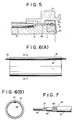
- FIG. 5 is an enlarged sectional diagram of a part of FIG. 1
- FIG. 6(A) is a longitudinal sectional diagram of the hose with built-in communication cable
- FIG. 6(B) is a sectional diagram as taken in the plane of the line A-A of FIG. 6(A)
- FIG. 7 is a conceptual diagram for the cable.
- l is a coupling which links two fire hoses with built-in communication cable, where the male and female units are constructed by coupling fittings 31 and 32.
- Each of the metal fittings 31 and 32 consists of an inner cylinder 5 in which an annular conductor 4 is provided on the opening end face on its one end and a hose with built-in communication cable is arranged, and an outer cylinder 6 engaged with the inner cylinder 5 and has a connection part.
- the inner cylinder 5 has a recessed groove 7 formed along circumferential direction on its opening end face, with an annular sealing member 8 inserted within the recessed groove 7.
- the sealing member 8 is so formed as to project its inner diameter side toward the axis of the hose with respect to the outer diameter side, with the inner diameter side protruding from the end face of the inner cylinder.
- annular electrical conductor 4 On the outer circumferential side of the sealing member 8 there is fitted integrally an annular electrical conductor 4 with one of its peripheries bent along the end face on the outer diameter side of the sealing member 8.
- the annular conductor 4 is made, in this case, of a metallic wire mesh with the mesh so arranged as to intersect obliquely the axial direction of the inner cylinder 5 in order to permit its elongation or contraction in the axial direction.
- the inner peripheral side and the outer peripheral side are surrounded by a sealing member.
- a sliding conductor 9 that makes contact with the annular conductor 4 is provided as shown in FIG. 5, and the sliding conductor 9 is connected to a lead line 9a which is provided penetrating through a flange part 5a of the inner cylinder 5.
- the lead line 9a is connected to the positive side 10a of a cable 10 of the hose 2 with built-in communication cable fitted on the outer peripheral surface of the inner cylinder 5.
- the negative side 10b of the cable 10 is connected to the inner cylinder 5 by means of soldering or the like.
- the outer cylinder 6 is fitted freely detachably to the inner cylinder 5, and is locked to the flange part 5a of the inner cylinder 5 to prevent dropping-off.
- the outer cylinder 6 consists of a small diameter part 6a which engages with the inner cylinder 5, and a large diameter part 6b which is provided with a pair of flanges 11 extending toward the cylindrical axis in a symmetrical manner, opening parts 12 formed with a predetermined spacing between the flanges 11, and a pair of engaging projections 13.
- the flange 11 is formed projecting for a predetermined length along the periphery from the inner peripheral face of the opening end of the large diameter part 6b. It is formed so as to increase the thickness gradually for a predetermined length from the opening part 12 along the circumferential direction of the outer cylinder.
- the engaging projection 13 is formed on the end face of the outer cylinder 6, projecting for a predetermined width toward the axial direction, and on its outer surface side there is formed a recessed part 14 that engages with the flange 11.
- the hose 2 with built-in communication cable as described in the above is formed by pasting a resin or rubber lining tube on the inner surface of the hose jacket as shown in FIGS. 6(A) and 6(B), with a cable 10 being disposed between the hose jacket 15 and the lining tube 16.
- the cable 10 is made, for example, by winding a copper wire 17 helically around a polyester resin core line 18, giving a coating 19 of polyvinyl chloride material, and further, winding a copper wire 20 helically over the coating 19, and giving a polyvinyl chloride coating 21 to form a coaxial cable, as shown in FIG. 7.
- the cable 10 is designed not to be broken even when it is elongated more (20%) than the elongation expected of the water pressure on the hose. It should be noted that use may also be made of a parallel bioxial type cable instead of the cable 10.
- the coupling fittings 31 and 32 assembled by matching the engaging projection 13 of one 31 of the coupling fittings with the opening part 12 of the other coupling fitting 32, and matching the engaging projection 13 of the other coupling fitting 32 with the opening part 12 of one of the coupling fitting 31.
Landscapes
- Engineering & Computer Science (AREA)
- General Engineering & Computer Science (AREA)
- Mechanical Engineering (AREA)
- Fire-Extinguishing By Fire Departments, And Fire-Extinguishing Equipment And Control Thereof (AREA)
Description
- The present invention relates to a coupling for fire hose with built-in communication cable.
- In fire fighting with a fire-fighting vehicle or the like, it is necessary to control the rate of water discharge depending upon the conditions at the scene of the fire. Because of this, what is usually done is to control the pressure of water supplied to the fire hose by adjusting the opening of the throttle valve of the engine or to control the rate of supplied water by opening or closing the discharge valve, based on information on the fire condition given to the personnel on the fire engine by means of radio communication or a liaison fire man.
- However, in a fire, it is general that the total number of fire hoses in use amounts to a large number because a plurality of fire hoses are connected to about four discharge ports provided for one fire engine. In particular, it is usual that there are gathered several or ten odd fire engines on the scene of the fire, each of them using fire hoses as described in the above. Accordingly, due to radio interference or insufficient number of available fighting personnel, it used to be difficult to transmit information that corresponds to the conditions of the fire scene necessary for adjusting the pressure or flow rate of supplied water, to persons stationed at the fire engine. Further, in the case of controlling the rate of water discharge by exclusively adjusting the rotation speed of the engine while leaving the valves of all of the discharge ports, flow rate of supplied water from each of the discharge ports is uniform, so that it was not possible to control the rate of supplied water in response to a detailed situation of the fire scene aimed at by each of the discharge ports.
- Under these circumstances, there was proposed in the past a coupling structure in which a connecting terminal for communication cable is arranged on each of the opposing faces of couplings with built-in communication cable that are to be mutually connected, by interposing a pressure-sensitive conductor whose resistance in the axial direction alone can be varied by the axial compression of the coupling between the connecting terminals (Japanese Patent Provisional Publication, No. 62-27972 (No. 27972/1987)). Such a hose has an advantage that it can import the conditions of the fire scene by means of a communication cable.
- In addition, there was disclosed a device in which a cable is incorporated in the axial direction of a ring-shaped insulating body in place of the pressure-sensitive conductor in the above system (Japanese Utility Model Provisional Publication, No. 63-103087 (No. 103087/1988) and Japanese Utility Model Application, No. 62-50735 (No. 50735/1987)).
- However, the pressure-sensitive conductor requires more cost and time for its manufacture, and moreover, the accuracy of change in the resistance obtained falls short of one's expectation. In addition, in the type with built-in cable, it tends to cause defective contact due to bending of the wire caused by the tightening of the coupling.
- Further, there used to be a difficulty that it leads to a delay in starting the fire fighting activity because of the time it requires for completing the connection of the couplings that have identical shape for both of the male and female parts.
- On the other hand, the prior art fire hose is connected to the coupling by inserting an end of the hose to a hose connecting part having saw-tooth engaging peripheral grooves, and binding it with a fastening piece.
- However, there was a problem that with such a connection structure it is not sufficient to prevent leakage of water.
- In view of this, the present applicants proposed previously a connective for fire hose which enables secure engaging of a fire hose with a coupling as well as prevention of leakage (Japanese Utility Model Publications, No. 58-28625 (No. 28625/1983) and No. 58-28626 (No. 28626/1983)).
- However, when the above-mentioned connective device is applied to the fire hose with built-in communication cable, there was created a new difficulty that the communication cable built in the hose was broken as a result of tightening with a tightening piece.
- The present invention has been contrived to solve the above-mentioned tasks, and, therefore, it is an object of the present invention to provide a coupling for fire hose with built-in communication cable which facilitates the hose connection work and enables to obtain a sure electrical connection as well as a water-tight construction.
- According to the present invention a coupling for a fire hose with built-in communication cable consists of two fittings, each of said fittings comprising: an inner cylinder, having a base end part fitted with a fire hose with built-in communication cable and annular sealing material for insulating and water-proofing the opening end face of said inner cylinder, an annular conductor connected to said communication cable an outer cylinder freely engaged with and held captive by an outer peripheral surface of said inner cylinder, said outer cylinder having an opening end surface corresponding to the opening end face of said inner cylinder; whereat said outer cylinder is provided with at least one pair of engaging projections which are arranged along the circumferential direction of said opening end surface of said outer cylinder and which form a male part, while opening windows in the outer cylinder form a female part; characterized in that the two fittings are of identical shape, the end face of said annular sealing material is formed as an inclined surface that protrudes out of said inner cylinder end face in a direction from an outer side of said inner cylinder towards an inner side of said inner cylinder, a groove is defined on the inner peripheral surface of each outer cylinder by a flange whose thickness increases along the circumferential direction from the opening windows such that when two outer cylinders are turned with respect to each other by being assembled so as to cause the flange of one outer cylinder to be engaged with the engaging projections of the other outer cylinder said outer cylinders can be brought into contact with each other, thereby bringing said annular sealing materials on said respective inner cylinder into a pressurized contact, while said annular conductors on said respective inner cylinders are brought into electrical contact.
- According to the invention the groove part on an outer cylinder is formed in such a way that when two outer cylinders are assembled with the engaging claw part on the partner outer cylinder is engaged with the groove and the two outer cylinders are turned relatively with each other, the two outer cylinders can be tightenend or loosened.
- By so doing, it becomes possible to bring the sealing materials on the respective inner cylinders into a pressurized contact.
- To explain the operation of the above device, two inner cylinders are matched mutually, and the outer cylinders are combined so as to bring the claw part and the opening window coincident with each other. Next, by relatively turning the outer cylinders one against the other, the claw part on one of the outer cylinders moves along the groove part of the partner outer cylinder, bringing the respective inner cylinders into pressurized contact. In this manner, annular conductors are provided on the respective end faces of the inner cylinders are mutually pressure contacted, establishing an electrical connection.
- As described in the above, according to the coupling for fire hose with built-in communication cable of the present invention (1), partner couplings are of the same shape, each having both of the male and female parts. Therefore, the work for connecting the couplings requires no need for taking the sense of each of the couplings into account, so that the operability can be enhanced.
- FIGS. 1(A) and 1(B) through FIG. 3 show the coupling for fire hose with built-in communication cable in accordance with the present invention, wherein FIG. 1(A) and FIG. 2 show longitudinal sectional diagrams, FIG. 1(B) shows a right elevation of FIG. 1(A), and FIG. 3 is a perspective view of FIG. 2. FIG. 4 is a perspective view showing the outer cylinder of FIG. 3, FIG. 5 is an enlarged sectional diagram of a part of FIG. 1, FIG. 6(A) is a longitudinal sectional diagram of the hose with built-in communication cable, FIG. 6(B) is a sectional diagram as taken in the plane of the line A-A of FIG. 6(A), and FIG. 7 is a conceptual diagram for the cable.
- Referring to the drawings, the present invention will now be described in detail.
- In FIGS. 1(A) and 1(B) to FIG. 4, l is a coupling which links two fire hoses with built-in communication cable, where the male and female units are constructed by
coupling fittings - Each of the
metal fittings inner cylinder 5 in which anannular conductor 4 is provided on the opening end face on its one end and a hose with built-in communication cable is arranged, and anouter cylinder 6 engaged with theinner cylinder 5 and has a connection part. - The
inner cylinder 5 has arecessed groove 7 formed along circumferential direction on its opening end face, with anannular sealing member 8 inserted within therecessed groove 7. The sealingmember 8 is so formed as to project its inner diameter side toward the axis of the hose with respect to the outer diameter side, with the inner diameter side protruding from the end face of the inner cylinder. - On the outer circumferential side of the sealing
member 8 there is fitted integrally an annularelectrical conductor 4 with one of its peripheries bent along the end face on the outer diameter side of the sealingmember 8. - The
annular conductor 4 is made, in this case, of a metallic wire mesh with the mesh so arranged as to intersect obliquely the axial direction of theinner cylinder 5 in order to permit its elongation or contraction in the axial direction. Here, after the wire mesh is wound in a cylindrical form, the inner peripheral side and the outer peripheral side are surrounded by a sealing member. On the inner surface of the recessed groove 7 asliding conductor 9 that makes contact with theannular conductor 4 is provided as shown in FIG. 5, and thesliding conductor 9 is connected to alead line 9a which is provided penetrating through aflange part 5a of theinner cylinder 5. Thelead line 9a is connected to thepositive side 10a of acable 10 of thehose 2 with built-in communication cable fitted on the outer peripheral surface of theinner cylinder 5. Thenegative side 10b of thecable 10 is connected to theinner cylinder 5 by means of soldering or the like. - On the other hand, the
outer cylinder 6 is fitted freely detachably to theinner cylinder 5, and is locked to theflange part 5a of theinner cylinder 5 to prevent dropping-off. Theouter cylinder 6 consists of asmall diameter part 6a which engages with theinner cylinder 5, and alarge diameter part 6b which is provided with a pair offlanges 11 extending toward the cylindrical axis in a symmetrical manner,opening parts 12 formed with a predetermined spacing between theflanges 11, and a pair ofengaging projections 13. - The
flange 11 is formed projecting for a predetermined length along the periphery from the inner peripheral face of the opening end of thelarge diameter part 6b. It is formed so as to increase the thickness gradually for a predetermined length from theopening part 12 along the circumferential direction of the outer cylinder. Theengaging projection 13 is formed on the end face of theouter cylinder 6, projecting for a predetermined width toward the axial direction, and on its outer surface side there is formed arecessed part 14 that engages with theflange 11. - The
hose 2 with built-in communication cable as described in the above is formed by pasting a resin or rubber lining tube on the inner surface of the hose jacket as shown in FIGS. 6(A) and 6(B), with acable 10 being disposed between thehose jacket 15 and thelining tube 16. Thecable 10 is made, for example, by winding acopper wire 17 helically around a polyesterresin core line 18, giving acoating 19 of polyvinyl chloride material, and further, winding acopper wire 20 helically over thecoating 19, and giving apolyvinyl chloride coating 21 to form a coaxial cable, as shown in FIG. 7. Thecable 10 is designed not to be broken even when it is elongated more (20%) than the elongation expected of the water pressure on the hose. It should be noted that use may also be made of a parallel bioxial type cable instead of thecable 10. - Now, assembling of couplings with the above-mentioned constitution will be described in what follows.
- The
coupling fittings engaging projection 13 of one 3₁ of the coupling fittings with theopening part 12 of the other coupling fitting 3₂, and matching theengaging projection 13 of the other coupling fitting 3₂ with theopening part 12 of one of the coupling fitting 3₁. - When the
outer cylinders 6 of thecoupling fittings engaging projections 13 with therespective flanges 11. With the above motion, theinner cylinders 5 and theouter cylinders 6 are brought closer to each other as thecoupling fittings flanges 11 of theengaging projections 13 is increased gradually along the circumferential direction of the outer cylinder. In this way, both sealingmembers 8 are mutually pressure contacted, bringing bothannular conductors 4 into contact and estblishing an electrical connection between thecables 10 ofhoses 2 with built-in communication cable.
Claims (1)
- A coupling (1) for a fire hose with built-in communication cable (10), consisting of two fittings (3₁,3₂) each of said fittings comprising:
an inner cylinder (5), having a base end part fitted with a fire hose (2) with build-in communication cable (10), and annular sealing material (8) for insulating and water-proofing the opening end face of said inner cylinder (5),
an annular conductor (4) connected to said communication cable (10); an outer cylinder (6) freely engaged with and held captive by an outer peripheral surface of said inner cylinder (5), said outer cylinder (6) having an opening end surface corresponding to the opening end face of said inner cylinder (5);
whereat said outer cylinder (6) is provided with at least one pair of engaging projections (13) which are arranged along the circumferential direction of said opening end surface of said outer cylinder (6) and which form a male part, while opening windows (12) in the outer cylinder (6) form a female part;
characterized in that the two fittings (3₁,3₂) are of identical shape,
the end face of said annular sealing material (8) is formed as an inclined surface that protrudes out of said inner cylinder end face in a direction from an outer side of said inner cylinder (5) towards an inner side of said inner cylinder (5),
a groove (12a) is defined on the inner peripheral surface of each outer cylinder (6) by a flange (11) whose thickness increases along the circumferential direction from the opening windows (12) such that when two outer cylinders (6) are turned with respect to each other by being assembled so as to cause the flange (11) of one outer cylinder (6) to be engaged with the engaging projections (13) of the other outer cylinder (6), said outer cylinders (6) can be brought into contact with each other,
thereby bringing said annular sealing materials (8) on said respective inner cylinder (5) into a pressurized contact, while said annular conductors (4) on said respective inner cylinders (5) are brought into electrical contact.
Applications Claiming Priority (4)
| Application Number | Priority Date | Filing Date | Title |
|---|---|---|---|
| JP63093992A JPH081278B2 (en) | 1988-04-15 | 1988-04-15 | Hose fitting with built-in line |
| JP93992/88 | 1988-04-15 | ||
| JP51035/88 | 1988-04-15 | ||
| JP5103588U JPH061713Y2 (en) | 1988-04-15 | 1988-04-15 | Connection structure between communication cable built-in fire hose and fitting |
Publications (3)
| Publication Number | Publication Date |
|---|---|
| EP0337055A2 EP0337055A2 (en) | 1989-10-18 |
| EP0337055A3 EP0337055A3 (en) | 1991-05-08 |
| EP0337055B1 true EP0337055B1 (en) | 1994-11-02 |
Family
ID=26391554
Family Applications (1)
| Application Number | Title | Priority Date | Filing Date |
|---|---|---|---|
| EP89100394A Expired - Lifetime EP0337055B1 (en) | 1988-04-15 | 1989-01-11 | Coupling for fire hose with built-in communication cable |
Country Status (3)
| Country | Link |
|---|---|
| US (1) | US4913657A (en) |
| EP (1) | EP0337055B1 (en) |
| DE (1) | DE68919110T2 (en) |
Families Citing this family (41)
| Publication number | Priority date | Publication date | Assignee | Title |
|---|---|---|---|---|
| US5404923A (en) * | 1993-05-26 | 1995-04-11 | Rockwell International Corporation | Apparatus for automated fueling of a launch vehicle |
| US5645302A (en) * | 1994-04-27 | 1997-07-08 | Sakura Rubber Co., Ltd. | Coupling apparatus |
| US5573414A (en) * | 1995-03-16 | 1996-11-12 | Mechanical Dynamics & Analysis, Inc. | Two piece electrical and fluidic connector and installation method therefore |
| US7498509B2 (en) * | 1995-09-28 | 2009-03-03 | Fiberspar Corporation | Composite coiled tubing end connector |
| US8678042B2 (en) | 1995-09-28 | 2014-03-25 | Fiberspar Corporation | Composite spoolable tube |
| US5921285A (en) * | 1995-09-28 | 1999-07-13 | Fiberspar Spoolable Products, Inc. | Composite spoolable tube |
| US5658159A (en) * | 1995-10-27 | 1997-08-19 | Biw Connector Systems, Inc. | Connector system and methods |
| US5959828A (en) * | 1996-07-16 | 1999-09-28 | Hydraflow | Coupling with insulated flanges |
| US5786976A (en) * | 1996-07-16 | 1998-07-28 | Hydraflow | Coupling with hard metallic ductile conductive coating |
| US7059881B2 (en) * | 1997-10-27 | 2006-06-13 | Halliburton Energy Services, Inc. | Spoolable composite coiled tubing connector |
| US6296066B1 (en) * | 1997-10-27 | 2001-10-02 | Halliburton Energy Services, Inc. | Well system |
| US6015298A (en) * | 1998-06-09 | 2000-01-18 | Truplast Konststofftechnik Gmbh | Vacuum-cleaner hose with electrical conductors |
| FR2792786A1 (en) * | 1999-04-21 | 2000-10-27 | Setmat | Flexible fluid passing tubing perforation testing having two wire transmission line transmission line inserted during manufacture covering complete tube surface and electromagnetic equipment testing transmission line discontinuities. |
| GB2391917B (en) * | 2001-04-27 | 2005-10-26 | Fiberspar Corp | Improved composite tubing |
| US6755675B2 (en) * | 2001-11-12 | 2004-06-29 | Itt Manufacturing Enterprises, Inc. | Fluid quick connector with secure electrical ground contact |
| US6929493B2 (en) * | 2003-05-06 | 2005-08-16 | Intelliserv, Inc. | Electrical contact for downhole drilling networks |
| US20050064761A1 (en) * | 2003-09-23 | 2005-03-24 | Spx Corporation | Induction heater coupling device and method |
| CA2490176C (en) | 2004-02-27 | 2013-02-05 | Fiberspar Corporation | Fiber reinforced spoolable pipe |
| US7156676B2 (en) * | 2004-11-10 | 2007-01-02 | Hydril Company Lp | Electrical contractors embedded in threaded connections |
| US8187687B2 (en) * | 2006-03-21 | 2012-05-29 | Fiberspar Corporation | Reinforcing matrix for spoolable pipe |
| US8839822B2 (en) | 2006-03-22 | 2014-09-23 | National Oilwell Varco, L.P. | Dual containment systems, methods and kits |
| CA2619808C (en) * | 2007-02-02 | 2015-04-14 | Fiberspar Corporation | Multi-cell spoolable pipe |
| US8746289B2 (en) | 2007-02-15 | 2014-06-10 | Fiberspar Corporation | Weighted spoolable pipe |
| US7762824B2 (en) * | 2007-03-08 | 2010-07-27 | National Coupling Company, Inc. | Hydraulic coupling member with electrical bonding contractor |
| US7922148B2 (en) | 2007-04-27 | 2011-04-12 | Carefusion 303, Inc. | Electronically activated access valve |
| FR2915788B1 (en) * | 2007-05-04 | 2012-05-25 | Airbus France | DEVICE FOR CONNECTING MULTI-SYSTEMS ON BOARD AN AIRCRAFT |
| DE102007041110B4 (en) * | 2007-08-30 | 2012-01-05 | Continental Automotive Gmbh | Electrical connection and use of an electrical connection |
| CA2641492C (en) | 2007-10-23 | 2016-07-05 | Fiberspar Corporation | Heated pipe and methods of transporting viscous fluid |
| CA2690926C (en) * | 2009-01-23 | 2018-03-06 | Fiberspar Corporation | Downhole fluid separation |
| US9206676B2 (en) | 2009-12-15 | 2015-12-08 | Fiberspar Corporation | System and methods for removing fluids from a subterranean well |
| US8955599B2 (en) | 2009-12-15 | 2015-02-17 | Fiberspar Corporation | System and methods for removing fluids from a subterranean well |
| US20110210542A1 (en) * | 2010-02-23 | 2011-09-01 | Makselon Christopher E | Connector for Spoolable Pipe |
| GB2485832A (en) * | 2010-11-26 | 2012-05-30 | Joseph Anthony Griffiths | A combined fluid coupling and data communication connection |
| US9890880B2 (en) | 2012-08-10 | 2018-02-13 | National Oilwell Varco, L.P. | Composite coiled tubing connectors |
| WO2018186249A1 (en) * | 2017-04-07 | 2018-10-11 | 日東工器株式会社 | Female pipe joint member provided with communication terminal |
| BE1025139B1 (en) * | 2017-04-14 | 2018-11-20 | Safran Aero Boosters S.A. | ELECTRICAL CONNECTOR FOR TURBOMACHINE HOUSING |
| EP3650737B1 (en) * | 2017-07-04 | 2024-12-04 | Nippon Pillar Packing Co., Ltd. | Connection structure for fluid device |
| CN108679332A (en) * | 2018-06-29 | 2018-10-19 | 祁县兰德消防水带制造有限公司 | A kind of communication water band |
| GB2582007A (en) * | 2019-03-08 | 2020-09-09 | Ross Robotics Ltd | Coupling system |
| EP4013519A4 (en) | 2019-08-14 | 2024-01-10 | Akron Brass Company | FIRE FIGHTING CONTROL SYSTEM |
| US11796109B2 (en) * | 2021-12-28 | 2023-10-24 | Cytiva Us Llc | Connector with rotatable tube |
Family Cites Families (12)
| Publication number | Priority date | Publication date | Assignee | Title |
|---|---|---|---|---|
| US499254A (en) * | 1893-06-13 | Electric hose-coupling | ||
| NL26030C (en) * | 1928-09-01 | |||
| US1890290A (en) * | 1932-02-26 | 1932-12-06 | William T Owens | Fire hose coupling |
| US3253245A (en) * | 1965-03-05 | 1966-05-24 | Chevron Res | Electrical signal transmission for well drilling |
| US3566002A (en) * | 1968-04-12 | 1971-02-23 | Kenard D Brown | Flexible tubing structure |
| US3518608A (en) * | 1968-10-28 | 1970-06-30 | Shell Oil Co | Telemetry drill pipe with thread electrode |
| FR2063376A5 (en) * | 1969-10-13 | 1971-07-09 | Beyeler Edouard | |
| US3879097A (en) * | 1974-01-25 | 1975-04-22 | Continental Oil Co | Electrical connectors for telemetering drill strings |
| JPS5831740B2 (en) * | 1977-09-13 | 1983-07-08 | 株式会社村田製作所 | Zinc oxide piezoelectric crystal film |
| US4366841A (en) * | 1980-04-30 | 1983-01-04 | Parker-Hannifin Corporation | Compensating hose fitting |
| DE3505045A1 (en) * | 1985-02-14 | 1986-08-14 | Messer Griesheim Gmbh, 6000 Frankfurt | INSULATED PLASTIC HOSE |
| JPS6227972A (en) * | 1985-07-30 | 1987-02-05 | 帝国繊維株式会社 | Fire hose fitting with built-in communication line |
-
1989
- 1989-01-04 US US07/293,295 patent/US4913657A/en not_active Expired - Fee Related
- 1989-01-11 EP EP89100394A patent/EP0337055B1/en not_active Expired - Lifetime
- 1989-01-11 DE DE68919110T patent/DE68919110T2/en not_active Expired - Fee Related
Also Published As
| Publication number | Publication date |
|---|---|
| US4913657A (en) | 1990-04-03 |
| EP0337055A2 (en) | 1989-10-18 |
| DE68919110T2 (en) | 1995-03-30 |
| DE68919110D1 (en) | 1994-12-08 |
| EP0337055A3 (en) | 1991-05-08 |
Similar Documents
| Publication | Publication Date | Title |
|---|---|---|
| US4913657A (en) | Coupling for fire hose with built-in communication cable | |
| US5466173A (en) | Longitudinally compressible coaxial cable connector | |
| US3393267A (en) | Connector for jacketed strip-wound metal hose | |
| US5525076A (en) | Longitudinally compressible coaxial cable connector | |
| US7077699B2 (en) | Axial compression electrical connector | |
| US5401184A (en) | Face plate for securing a waterproof connection between electrical plug and receptacle | |
| US4810832A (en) | Sealed cable connector | |
| US7207838B2 (en) | Coaxial connectors | |
| EP0485437B1 (en) | Abdichtungsvorrichtung für eine unter Druck stehende Leitung | |
| JPH03212113A (en) | flexible cable termination | |
| US4453034A (en) | One die system of compression transmission fittings | |
| EP0771990B1 (en) | Pneumatic connector | |
| KR101041392B1 (en) | Cable and Cable Connection Assemblies | |
| EP0310975B1 (en) | Electrical sensor with housing | |
| US4488139A (en) | Electrical connector | |
| US4050773A (en) | Battery terminal connector | |
| JPH081278B2 (en) | Hose fitting with built-in line | |
| JPH10189127A (en) | Grommet | |
| US5780770A (en) | Fluid cooled electrical conductor assembly | |
| US4166921A (en) | Flexible housing, in-line electronic | |
| US2684398A (en) | Conduit ferrule | |
| JPS6227972A (en) | Fire hose fitting with built-in communication line | |
| US3395429A (en) | End fittings for push-pull cable cores | |
| EP1441167B1 (en) | Coupling | |
| JP2002199546A (en) | Box for indoor wiring |
Legal Events
| Date | Code | Title | Description |
|---|---|---|---|
| PUAI | Public reference made under article 153(3) epc to a published international application that has entered the european phase |
Free format text: ORIGINAL CODE: 0009012 |
|
| AK | Designated contracting states |
Kind code of ref document: A2 Designated state(s): BE CH DE FR GB IT LI NL |
|
| PUAL | Search report despatched |
Free format text: ORIGINAL CODE: 0009013 |
|
| AK | Designated contracting states |
Kind code of ref document: A3 Designated state(s): BE CH DE FR GB IT LI NL |
|
| 17P | Request for examination filed |
Effective date: 19910911 |
|
| 17Q | First examination report despatched |
Effective date: 19921217 |
|
| GRAA | (expected) grant |
Free format text: ORIGINAL CODE: 0009210 |
|
| AK | Designated contracting states |
Kind code of ref document: B1 Designated state(s): BE CH DE FR GB IT LI NL |
|
| PG25 | Lapsed in a contracting state [announced via postgrant information from national office to epo] |
Ref country code: IT Free format text: LAPSE BECAUSE OF FAILURE TO SUBMIT A TRANSLATION OF THE DESCRIPTION OR TO PAY THE FEE WITHIN THE PRE;WARNING: LAPSES OF ITALIAN PATENTS WITH EFFECTIVE DATE BEFORE 2007 MAY HAVE OCCURRED AT ANY TIME BEFORE 2007. THE CORRECT EFFECTIVE DATE MAY BE DIFFERENT FROM THE ONE RECORDED.SCRIBED TIME-LIMIT Effective date: 19941102 Ref country code: CH Effective date: 19941102 Ref country code: NL Effective date: 19941102 Ref country code: BE Effective date: 19941102 Ref country code: LI Effective date: 19941102 |
|
| REF | Corresponds to: |
Ref document number: 68919110 Country of ref document: DE Date of ref document: 19941208 |
|
| ET | Fr: translation filed | ||
| REG | Reference to a national code |
Ref country code: CH Ref legal event code: PL |
|
| NLV1 | Nl: lapsed or annulled due to failure to fulfill the requirements of art. 29p and 29m of the patents act | ||
| PLBI | Opposition filed |
Free format text: ORIGINAL CODE: 0009260 |
|
| 26 | Opposition filed |
Opponent name: MAX WIDENMANN ARMATURENFABRIK Effective date: 19950728 |
|
| PLBF | Reply of patent proprietor to notice(s) of opposition |
Free format text: ORIGINAL CODE: EPIDOS OBSO |
|
| PLBO | Opposition rejected |
Free format text: ORIGINAL CODE: EPIDOS REJO |
|
| PLBN | Opposition rejected |
Free format text: ORIGINAL CODE: 0009273 |
|
| STAA | Information on the status of an ep patent application or granted ep patent |
Free format text: STATUS: OPPOSITION REJECTED |
|
| 27O | Opposition rejected |
Effective date: 19961010 |
|
| REG | Reference to a national code |
Ref country code: GB Ref legal event code: IF02 |
|
| PGFP | Annual fee paid to national office [announced via postgrant information from national office to epo] |
Ref country code: GB Payment date: 20050105 Year of fee payment: 17 |
|
| PGFP | Annual fee paid to national office [announced via postgrant information from national office to epo] |
Ref country code: FR Payment date: 20050110 Year of fee payment: 17 |
|
| PGFP | Annual fee paid to national office [announced via postgrant information from national office to epo] |
Ref country code: DE Payment date: 20050128 Year of fee payment: 17 |
|
| PG25 | Lapsed in a contracting state [announced via postgrant information from national office to epo] |
Ref country code: GB Free format text: LAPSE BECAUSE OF NON-PAYMENT OF DUE FEES Effective date: 20060111 |
|
| PG25 | Lapsed in a contracting state [announced via postgrant information from national office to epo] |
Ref country code: FR Free format text: LAPSE BECAUSE OF NON-PAYMENT OF DUE FEES Effective date: 20060131 |
|
| PG25 | Lapsed in a contracting state [announced via postgrant information from national office to epo] |
Ref country code: DE Free format text: LAPSE BECAUSE OF NON-PAYMENT OF DUE FEES Effective date: 20060801 |
|
| GBPC | Gb: european patent ceased through non-payment of renewal fee |
Effective date: 20060111 |
|
| REG | Reference to a national code |
Ref country code: FR Ref legal event code: ST Effective date: 20060929 |