EP0336782A2 - Schi-Alarmsystem - Google Patents
Schi-Alarmsystem Download PDFInfo
- Publication number
- EP0336782A2 EP0336782A2 EP89303521A EP89303521A EP0336782A2 EP 0336782 A2 EP0336782 A2 EP 0336782A2 EP 89303521 A EP89303521 A EP 89303521A EP 89303521 A EP89303521 A EP 89303521A EP 0336782 A2 EP0336782 A2 EP 0336782A2
- Authority
- EP
- European Patent Office
- Prior art keywords
- unit
- movement
- alarm
- mode
- alarm unit
- Prior art date
- Legal status (The legal status is an assumption and is not a legal conclusion. Google has not performed a legal analysis and makes no representation as to the accuracy of the status listed.)
- Withdrawn
Links
- 230000033001 locomotion Effects 0.000 claims abstract description 41
- 238000012360 testing method Methods 0.000 claims description 13
- 229910052751 metal Inorganic materials 0.000 claims description 3
- 239000002184 metal Substances 0.000 claims description 3
- 238000001514 detection method Methods 0.000 abstract description 4
- 238000013461 design Methods 0.000 description 5
- 238000010586 diagram Methods 0.000 description 5
- 230000027455 binding Effects 0.000 description 3
- 238000009739 binding Methods 0.000 description 3
- 239000013078 crystal Substances 0.000 description 3
- 230000000295 complement effect Effects 0.000 description 2
- 230000000694 effects Effects 0.000 description 2
- 238000005516 engineering process Methods 0.000 description 2
- 238000002474 experimental method Methods 0.000 description 2
- 238000004519 manufacturing process Methods 0.000 description 2
- 238000000034 method Methods 0.000 description 2
- 235000014676 Phragmites communis Nutrition 0.000 description 1
- 229910000831 Steel Inorganic materials 0.000 description 1
- 230000002745 absorbent Effects 0.000 description 1
- 239000002250 absorbent Substances 0.000 description 1
- 238000004458 analytical method Methods 0.000 description 1
- 230000003466 anti-cipated effect Effects 0.000 description 1
- 230000005540 biological transmission Effects 0.000 description 1
- 230000006835 compression Effects 0.000 description 1
- 238000007906 compression Methods 0.000 description 1
- 238000012790 confirmation Methods 0.000 description 1
- 238000005553 drilling Methods 0.000 description 1
- QSHDDOUJBYECFT-UHFFFAOYSA-N mercury Chemical compound [Hg] QSHDDOUJBYECFT-UHFFFAOYSA-N 0.000 description 1
- 229910052753 mercury Inorganic materials 0.000 description 1
- 238000009877 rendering Methods 0.000 description 1
- 230000000284 resting effect Effects 0.000 description 1
- 230000000717 retained effect Effects 0.000 description 1
- 238000010079 rubber tapping Methods 0.000 description 1
- 230000005236 sound signal Effects 0.000 description 1
- 239000010959 steel Substances 0.000 description 1
- 238000012795 verification Methods 0.000 description 1
- 230000000007 visual effect Effects 0.000 description 1
- XLYOFNOQVPJJNP-UHFFFAOYSA-N water Substances O XLYOFNOQVPJJNP-UHFFFAOYSA-N 0.000 description 1
- 238000004078 waterproofing Methods 0.000 description 1
Images


Classifications
-
- A—HUMAN NECESSITIES
- A63—SPORTS; GAMES; AMUSEMENTS
- A63C—SKATES; SKIS; ROLLER SKATES; DESIGN OR LAYOUT OF COURTS, RINKS OR THE LIKE
- A63C11/00—Accessories for skiing or snowboarding
- A63C11/003—Signalling devices, e.g. acoustical or visual
Definitions
- the invention relates to a ski alarm system and provides an alarm unit for a ski which allows the ski to be detected when buried in snow.
- a unit has use in detecting the whereabouts of a skier who may have been buried in an accident and also in finding lost skis.
- a preferred feature of the invention is the additional use of the unit in detecting attempted theft of skis.
- an alarm unit for a ski comprising a sounder for emitting an audible alarm signal; a battery powered circuit connected to energise the sounder; and a movement responsive unit connected to the circuit, the circuit including a timer and being arranged to activate the sounder when the movement responsive unit has given no output representative of movement for a predetermined time.
- the alarm unit may, instead of being designed as an accessory to be fixed to a ski, be incorporated in the ski binding.
- the circuit has at least two modes to which it may be set, namely a ski mode in which, as described above, lack of movement is caused to energise the sounder, and a theft mode in which the converse is true, and the sounder is energised on detection of movement by the movement-responsive unit.
- the circuit has additionally a test mode in which the alarm functions may be tested and a standby mode in which the circuit is clear to be set to one of the other modes.
- Mode setting may be accomplished by mechanical or magnetic reed switches associated with the alarm unit.
- a remote control unit is provided.
- the remote control unit may effect control by audio signals, perhaps of ultrasonic frequencies or by radio control.
- the remote control unit is an infrared transmitter which issues coded infrared signals to a receiver unit incorporated in the alarm unit.
- the movement responsive unit comprises a housing with walls, internal electrodes on different walls of the housing and a number of discrete electrically conductive members in the housing which are free to move and which rest in contact with each other and with the electrodes to form conductive bridge between the electrodes, movement of the members being effective to change the resistance presented by the members between the electrodes.
- the members are preferable metal balls
- the housing may be oil-filled.
- the sounder is preferably a piezo-electric unit. Extensive experiments have established that in typical operating conditions there is an optimum frequency range which, for a given power output, offers the best sound detection and position location characteristics. This frequency range is between 2000 and 4000 Hz.
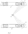
- the system comprises alarm units 1 and 2 mounted on respective skis 3 and 4.
- a control unit 5 is hand held and issues infra-red signals to control the mode settings of the alarm units.
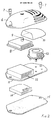
- FIG 2 shows an alarm unit comprising a cover 6, mounting screws 7, a printed circuit board assembly 8 with a light emitting diode 9, an acoustically transparent cover 10, a base plate 11 which carries a battery housing/pcb mount 12 and a piezo-electric sounder 13.
- a motion detector (not shown separately). This is described in detail with reference to Figure 4.
- a suitable commercial motion detector is made by Kelvin Impex under the designation MAC 702. This kind of detector is found by experiment to be superior to a mercury switch or trembler switch.
- the battery is shown at 14 and a water-proof gasket at 15.
- Figure 3 shows the infra-red control unit 5 comprising an upper case 16, and a lower case 17, a battery 18, a battery cover 19, and a printed circuit board assembly 20 having an infra-red transmitter 21 and an acuating switch 22.
- a spring-loaded reel has a clip-on attachment 23 to allow the unit to be clipped to clothing.
- the overall philosophy and design concept considered the following:- ability to withstand vibration; Ability to withstand extremes of temperature; Imperviousness to moisture; Small size, weight and low profile for mounting on skis; and Low power consumption for minimum battery size.
- ASIC Application Specific Integrated Circuits
- ASIC Application Specific Integrated Circuits
- S M D Surface Mount Device refers to the way in which the printed circuit board is manufactured. Instead of conventional leaded components soldered onto a circuit board, S M D places the components directly onto the board which are then soldered in an infra red oven and subsequently protectively coated. This concept results in a small P C B which is insensitive to moisture and vibration, is compact, and very economical to manufacture.
- the motion detector comprising a cylindrical housing having two metal end walls 41, 42 which constitute electrodes. Leads 43, 44 connect the detector to the alarm circuit.
- the end walls are separated by an insulating cylindrical wall 45.
- Within the housing is a collection of steel balls 46 which rest on each other and against the end walls, thereby making bridging contact between the end walls.
- the housing is vibrated or shaken the contacts made by the balls are disturbed and there is a consequent electrical resistance change between the end walls. This is detected as a movement signal by the alarm circuit.
- circuit of the controller 5 This comprises an application specific integrated circuit (ASIC) 47 which has external components including a battery (not shown) with a manual 'on' switch 48.
- ASIC application specific integrated circuit
- Two test input lines 49, 50 connected to receive manually controllable inputs are effective to test the transmitter.
- a test output 51 is available to allow analysis of the test results.
- a status LED 52 is provided to indicate the status of the transmitter.
- An infrared emitter 53 with associated driving transistor 54 and resistor 55 is provided to give a modulated pulsed output. Pulse timing is governed by a 32 kHz crystal 56 and the particular modulation is determined by a code track 57. This is constituted by a set of conductive tracks connecting both a 9 volt line 58 and an earth line 59 to twelve output pins of the ASIC. The operative code for the transmitter is determined by breaking the track to each pin either from the line 58 or from the line 59. Thus, a particular set of voltages is applied as a binary parallel number to the twelve pins. This code corresponds to the same code set in the associated receiver, thereby ensuring that the liklihood of interference with other transmitter/receiver sets is remote.
- FIG. 6 there is shown a block diagram of the receiver in the alarm unit.
- This comprises an ASIC 60 with external components including an infra-red receiver diode 61 and associated RC network 62. Pulses from the diode 61 are applied to an operational amplifier 63 forming part of the ASIC.
- a code track 64 of the same nature and configuration as track 57 of the transmitter is provided.
- a 32 kHz crystal 65 provides clock pulses and an LED 66 indicates the status of the receiver.
- the motion detector is represented at 67 in Figure 6 and provides an input to a timer circuit 68 in the ASIC.
- a mode selector unit 69 in the ASIC responds to inputs decoded from the diode 61 and according to the mode determined by the transmitted pulses controls the timer circuit.
- the timer circuit is controlled to be reset by input from the motion detector. If a predetermined time is allowed to elapse without a reset from the motion detector then the timer circuit activates a drive circuit 70 in the ASIC which causes the piezo-electric sounder 71 to emit a warbling alarm tone.
- the timer circuit is controlled to activate the drive circuit it successive movements are detected within a predetermined time.
- FIG. 7 there is shown a transmitter for an alternative system of control.
- the transmitter is a radio transmitter instead of an infra-red transmitter.
- An ASIC 73 is powered by a battery 74 via a manual switch 75.
- a 32 kHz crystal 76 gives clock pulses and a code track 77 of the kind described above provides a code for pairing a transmitter and receiver.
- Output from the ASIC modulates a 149 MHz radio transmitter 78.
- a complementary radio receiver is provided on each ski to respond to the transmitter and perform the functions outlined above for the infra-red receiver.
- An alternative arrangement is to provide that the alarm emits a "warbling" type resonse between the two frequency extremes. This gives maximum audibility and also when in SKI MODE allows ease of pin-pointing the skis.
- the remote control is momentarily operated by squeezing the case. This in turn activates an internal switch and causes an encoded infra red transmission to be emitted.
- the chance of two identical codes being assigned to two transmitters is 1 in 4096 which are acceptable especially when weighting the chances of these two units being in the same place at any one time.
- the enablement procedure is as follows:- Enable SKI MODE press once. Enable THEFT MODE press two times. Enable TEST MODE press three times. Reenable STANDBY MODE from any of above press once.
- the system must always return to the STANDBY MODE prior to changing the MODE of operation. As each MODE is enabled the ski based alarms will momentarily sound at a reduced power level. Whilst both the ski based and remote control based LED lights will continually flash a coded sequence indicating visually the enabled MODE.
- the remote control unit has a range of approximately 2 metres thus allowing ease of operation when the skis are either being worn or left alone.
- the S B U's Ski Based Units
- the S B U's will indicate audibly that a new mode has just been enabled and visually (on both the S B U's and the remote control) on a continuous basis which mode is currently enabled.
- the visual status is shown by the LED'S flashing the coded sequence set out below:-
- the design of the case has been developed to minimise snow and ice build up and to complement the present ski binding designs in aesthetics.
- the internal case design has been similarily developed in order to enhance the sound level emmision.
- the mounting of the S B U's is achieved by using two set hexagonal socket head screws per unit connecting the case via a rubber gasket to the ski. This method of mounting results in a deformation absorbent, water resistant seal which is required when considering the ski deformations locally during operation.
- shouldered self tapping set screws are employed.
- the S B U is screwed down until the shoulder bottoms out on the ski face.
- Such an infra-red controlled theft-only unit can be made inexpensive strictlyly and can be made to sound the alarm on detection of any required movement.
- the unit can be used to detect burglars by the movement of doors or windows, or the theft of any article to which the alarm unit is fixed or is resting - e.g. bicycles, motorcycles, television sets etc.
- the above-described system for avoiding unnecessary alarms in the event of accidental movement is useful for such arrangements in which the alarm unit is fixed to the article to be protected.
- the delay time of 16 seconds can be changed to suit individual circumstances.
Landscapes
- Burglar Alarm Systems (AREA)
Applications Claiming Priority (2)
| Application Number | Priority Date | Filing Date | Title |
|---|---|---|---|
| GB888808337A GB8808337D0 (en) | 1988-04-08 | 1988-04-08 | Alarm system |
| GB8808337 | 1988-04-08 |
Publications (2)
| Publication Number | Publication Date |
|---|---|
| EP0336782A2 true EP0336782A2 (de) | 1989-10-11 |
| EP0336782A3 EP0336782A3 (en) | 1990-09-19 |
Family
ID=10634864
Family Applications (1)
| Application Number | Title | Priority Date | Filing Date |
|---|---|---|---|
| EP19890303521 Withdrawn EP0336782A3 (en) | 1988-04-08 | 1989-04-10 | Ski alarm system |
Country Status (2)
| Country | Link |
|---|---|
| EP (1) | EP0336782A3 (de) |
| GB (1) | GB8808337D0 (de) |
Cited By (17)
| Publication number | Priority date | Publication date | Assignee | Title |
|---|---|---|---|---|
| FR2741276A1 (fr) * | 1995-11-21 | 1997-05-23 | Suntech | Dispositif antivol autonome pour ski ou assimile ski |
| WO1999043398A1 (en) * | 1998-02-25 | 1999-09-02 | Bruce Chittenden | Sport apparatus locator device |
| EP1007975A4 (de) * | 1997-06-02 | 2002-04-10 | Phatrat Tech Inc | Sport-überwachungssystem zur bestimmung von luftzeit, geschwindigkeit, absorbierter leistung, und anderer grössen wie fallhöhe |
| US6659494B1 (en) * | 2000-08-10 | 2003-12-09 | Ralph M. Martin | Backwards release ski binding on a pivot plate mount |
| US6769711B1 (en) | 2000-08-10 | 2004-08-03 | Ralph M. Martin | Gas powered backwards release ski binding |
| US6856934B2 (en) | 1994-11-21 | 2005-02-15 | Phatrat Technology, Inc. | Sport monitoring systems and associated methods |
| US6963818B2 (en) | 1994-11-21 | 2005-11-08 | Phatrat Technology, Inc. | Mobile speedometer system and associated methods |
| US7104564B2 (en) * | 2000-08-10 | 2006-09-12 | Martin Ralph M | Backwards release ski binding |
| US7552031B2 (en) | 2000-12-15 | 2009-06-23 | Apple Inc. | Personal items network, and associated methods |
| US7643895B2 (en) | 2006-05-22 | 2010-01-05 | Apple Inc. | Portable media device with workout support |
| US7698101B2 (en) | 2007-03-07 | 2010-04-13 | Apple Inc. | Smart garment |
| US7813715B2 (en) | 2006-08-30 | 2010-10-12 | Apple Inc. | Automated pairing of wireless accessories with host devices |
| US7911339B2 (en) | 2005-10-18 | 2011-03-22 | Apple Inc. | Shoe wear-out sensor, body-bar sensing system, unitless activity assessment and associated methods |
| US7913297B2 (en) | 2006-08-30 | 2011-03-22 | Apple Inc. | Pairing of wireless devices using a wired medium |
| US8073984B2 (en) | 2006-05-22 | 2011-12-06 | Apple Inc. | Communication protocol for use with portable electronic devices |
| US9137309B2 (en) | 2006-05-22 | 2015-09-15 | Apple Inc. | Calibration techniques for activity sensing devices |
| US9868041B2 (en) | 2006-05-22 | 2018-01-16 | Apple, Inc. | Integrated media jukebox and physiologic data handling application |
Family Cites Families (5)
| Publication number | Priority date | Publication date | Assignee | Title |
|---|---|---|---|---|
| US4057791A (en) * | 1976-02-09 | 1977-11-08 | Bimmerle Charles F | Motion responsive alarm system |
| ZA803163B (en) * | 1979-06-02 | 1981-05-27 | E Cohen | Personal monitoring device |
| EP0047629A1 (de) * | 1980-09-09 | 1982-03-17 | Winter And Summer Pursuits Limited | Skianzeigegerät |
| FR2549262B1 (fr) * | 1983-07-13 | 1986-05-30 | Seram Ets M Bohn | Installation de surveillance et de protection d'un homme seul travaillant dans une zone dangereuse ou isolee |
| US4535322A (en) * | 1983-08-01 | 1985-08-13 | Yeski Frederick R | Ski theft alarm and runaway ski locator |
-
1988
- 1988-04-08 GB GB888808337A patent/GB8808337D0/en active Pending
-
1989
- 1989-04-10 EP EP19890303521 patent/EP0336782A3/en not_active Withdrawn
Cited By (46)
| Publication number | Priority date | Publication date | Assignee | Title |
|---|---|---|---|---|
| US8036851B2 (en) | 1994-11-21 | 2011-10-11 | Apple Inc. | Activity monitoring systems and methods |
| US6856934B2 (en) | 1994-11-21 | 2005-02-15 | Phatrat Technology, Inc. | Sport monitoring systems and associated methods |
| US6963818B2 (en) | 1994-11-21 | 2005-11-08 | Phatrat Technology, Inc. | Mobile speedometer system and associated methods |
| US7451056B2 (en) | 1994-11-21 | 2008-11-11 | Phatrat Technology, Llc | Activity monitoring systems and methods |
| US7512515B2 (en) | 1994-11-21 | 2009-03-31 | Apple Inc. | Activity monitoring systems and methods |
| US8352211B2 (en) | 1994-11-21 | 2013-01-08 | Apple Inc. | Activity monitoring systems and methods |
| FR2741276A1 (fr) * | 1995-11-21 | 1997-05-23 | Suntech | Dispositif antivol autonome pour ski ou assimile ski |
| EP1007975A4 (de) * | 1997-06-02 | 2002-04-10 | Phatrat Tech Inc | Sport-überwachungssystem zur bestimmung von luftzeit, geschwindigkeit, absorbierter leistung, und anderer grössen wie fallhöhe |
| WO1999043398A1 (en) * | 1998-02-25 | 1999-09-02 | Bruce Chittenden | Sport apparatus locator device |
| US6659494B1 (en) * | 2000-08-10 | 2003-12-09 | Ralph M. Martin | Backwards release ski binding on a pivot plate mount |
| US6769711B1 (en) | 2000-08-10 | 2004-08-03 | Ralph M. Martin | Gas powered backwards release ski binding |
| US7104564B2 (en) * | 2000-08-10 | 2006-09-12 | Martin Ralph M | Backwards release ski binding |
| US10639552B2 (en) | 2000-12-15 | 2020-05-05 | Apple Inc. | Personal items network, and associated methods |
| US10427050B2 (en) | 2000-12-15 | 2019-10-01 | Apple Inc. | Personal items network, and associated methods |
| US10406445B2 (en) | 2000-12-15 | 2019-09-10 | Apple Inc. | Personal items network, and associated methods |
| US10080971B2 (en) | 2000-12-15 | 2018-09-25 | Apple Inc. | Personal items network, and associated methods |
| US9643091B2 (en) | 2000-12-15 | 2017-05-09 | Apple Inc. | Personal items network, and associated methods |
| US8280682B2 (en) | 2000-12-15 | 2012-10-02 | Tvipr, Llc | Device for monitoring movement of shipped goods |
| US8688406B2 (en) | 2000-12-15 | 2014-04-01 | Apple Inc. | Personal items network, and associated methods |
| US8396687B2 (en) | 2000-12-15 | 2013-03-12 | Phatrat Technology, Llc | Machine logic airtime sensor for board sports |
| US8374825B2 (en) | 2000-12-15 | 2013-02-12 | Apple Inc. | Personal items network, and associated methods |
| US7627451B2 (en) | 2000-12-15 | 2009-12-01 | Apple Inc. | Movement and event systems and associated methods |
| US7552031B2 (en) | 2000-12-15 | 2009-06-23 | Apple Inc. | Personal items network, and associated methods |
| US8280681B2 (en) | 2000-12-15 | 2012-10-02 | Phatrat Technology, Llc | Pressure-based weight monitoring system for determining improper walking or running |
| US8217788B2 (en) | 2005-10-18 | 2012-07-10 | Vock Curtis A | Shoe wear-out sensor, body-bar sensing system, unitless activity assessment and associated methods |
| US9968158B2 (en) | 2005-10-18 | 2018-05-15 | Apple Inc. | Shoe wear-out sensor, body-bar sensing system, unitless activity assessment and associated methods |
| US12419380B2 (en) | 2005-10-18 | 2025-09-23 | Apple Inc. | Unitless activity assessment and associated methods |
| US11786006B2 (en) | 2005-10-18 | 2023-10-17 | Apple Inc. | Unitless activity assessment and associated methods |
| US11140943B2 (en) | 2005-10-18 | 2021-10-12 | Apple Inc. | Unitless activity assessment and associated methods |
| US10645991B2 (en) | 2005-10-18 | 2020-05-12 | Apple Inc. | Unitless activity assessment and associated methods |
| US8749380B2 (en) | 2005-10-18 | 2014-06-10 | Apple Inc. | Shoe wear-out sensor, body-bar sensing system, unitless activity assessment and associated methods |
| US10376015B2 (en) | 2005-10-18 | 2019-08-13 | Apple Inc. | Shoe wear-out sensor, body-bar sensing system, unitless activity assessment and associated methods |
| US7911339B2 (en) | 2005-10-18 | 2011-03-22 | Apple Inc. | Shoe wear-out sensor, body-bar sensing system, unitless activity assessment and associated methods |
| US9578927B2 (en) | 2005-10-18 | 2017-02-28 | Apple Inc. | Shoe wear-out sensor, body-bar sensing system, unitless activity assessment and associated methods |
| US9868041B2 (en) | 2006-05-22 | 2018-01-16 | Apple, Inc. | Integrated media jukebox and physiologic data handling application |
| US8346987B2 (en) | 2006-05-22 | 2013-01-01 | Apple Inc. | Communication protocol for use with portable electronic devices |
| US9154554B2 (en) | 2006-05-22 | 2015-10-06 | Apple Inc. | Calibration techniques for activity sensing devices |
| US9137309B2 (en) | 2006-05-22 | 2015-09-15 | Apple Inc. | Calibration techniques for activity sensing devices |
| US7643895B2 (en) | 2006-05-22 | 2010-01-05 | Apple Inc. | Portable media device with workout support |
| US8060229B2 (en) | 2006-05-22 | 2011-11-15 | Apple Inc. | Portable media device with workout support |
| US8073984B2 (en) | 2006-05-22 | 2011-12-06 | Apple Inc. | Communication protocol for use with portable electronic devices |
| US7913297B2 (en) | 2006-08-30 | 2011-03-22 | Apple Inc. | Pairing of wireless devices using a wired medium |
| US7813715B2 (en) | 2006-08-30 | 2010-10-12 | Apple Inc. | Automated pairing of wireless accessories with host devices |
| US8181233B2 (en) | 2006-08-30 | 2012-05-15 | Apple Inc. | Pairing of wireless devices using a wired medium |
| US7698101B2 (en) | 2007-03-07 | 2010-04-13 | Apple Inc. | Smart garment |
| US8099258B2 (en) | 2007-03-07 | 2012-01-17 | Apple Inc. | Smart garment |
Also Published As
| Publication number | Publication date |
|---|---|
| EP0336782A3 (en) | 1990-09-19 |
| GB8808337D0 (en) | 1988-05-11 |
Similar Documents
| Publication | Publication Date | Title |
|---|---|---|
| EP0336782A2 (de) | Schi-Alarmsystem | |
| US11570710B2 (en) | Remotely detectable transportable game and fishing alarm system | |
| US6756901B2 (en) | Multi function electronic personal monitor and radio telemetry cell system | |
| US4959637A (en) | Emergency signaling device | |
| US5748087A (en) | Remote personal security alarm system | |
| US5854588A (en) | Home security system for detecting an intrusion into a monitored area by an infrared detector | |
| US4189720A (en) | Repeater for smoke and similar alarms | |
| US5867105A (en) | Wireless alarm system | |
| EP0109184A3 (de) | Identifikationsverfahren | |
| US5235321A (en) | Ski alarm system | |
| ATE298913T1 (de) | Warnsystem mit sendergesteuerter mehrfachauslösung und tragbarem empfänger- vibrator | |
| FI76659B (fi) | Fjaerrstyrningssystem foer elektriska och elektroniska apparater, speciellt foer underhaollningselektronikapparater. | |
| US5406256A (en) | Remote sensor and motion alarm system | |
| US4633231A (en) | Monitoring arrangement | |
| US5828304A (en) | Pool monitoring system | |
| GB2458877A (en) | Distress Alarm System | |
| GB2343776A (en) | Child safety distance alarm system | |
| EP4163892B1 (de) | Tragbare sicherheitsvorrichtung | |
| GB1595788A (en) | Warning systems | |
| GB2218552A (en) | Electric light installation | |
| EP0883096A3 (de) | Notrufübertragungsvorrichtung | |
| US20030162508A1 (en) | Miniature electronic personal locator beacon | |
| JPH02309983A (ja) | 警報ユニット | |
| GB2228120A (en) | Intruder alarm system disarmed by radio signal | |
| WO2000026729A1 (en) | Alarm for electronic equipment |
Legal Events
| Date | Code | Title | Description |
|---|---|---|---|
| PUAI | Public reference made under article 153(3) epc to a published international application that has entered the european phase |
Free format text: ORIGINAL CODE: 0009012 |
|
| AK | Designated contracting states |
Kind code of ref document: A2 Designated state(s): AT BE CH DE ES FR GB GR IT LI LU NL SE |
|
| PUAL | Search report despatched |
Free format text: ORIGINAL CODE: 0009013 |
|
| AK | Designated contracting states |
Kind code of ref document: A3 Designated state(s): AT BE CH DE ES FR GB GR IT LI LU NL SE |
|
| 17P | Request for examination filed |
Effective date: 19910321 |
|
| R17P | Request for examination filed (corrected) |
Effective date: 19910319 |
|
| 17Q | First examination report despatched |
Effective date: 19920505 |
|
| STAA | Information on the status of an ep patent application or granted ep patent |
Free format text: STATUS: THE APPLICATION IS DEEMED TO BE WITHDRAWN |
|
| 18D | Application deemed to be withdrawn |
Effective date: 19921117 |