EP0336781A2 - Vehicle frame structure - Google Patents
Vehicle frame structure Download PDFInfo
- Publication number
- EP0336781A2 EP0336781A2 EP89303500A EP89303500A EP0336781A2 EP 0336781 A2 EP0336781 A2 EP 0336781A2 EP 89303500 A EP89303500 A EP 89303500A EP 89303500 A EP89303500 A EP 89303500A EP 0336781 A2 EP0336781 A2 EP 0336781A2
- Authority
- EP
- European Patent Office
- Prior art keywords
- continuous
- rails
- welded
- vehicle frame
- topmost
- Prior art date
- Legal status (The legal status is an assumption and is not a legal conclusion. Google has not performed a legal analysis and makes no representation as to the accuracy of the status listed.)
- Withdrawn
Links
- 238000010276 construction Methods 0.000 description 6
- 238000000034 method Methods 0.000 description 4
- 238000003466 welding Methods 0.000 description 3
- 238000010521 absorption reaction Methods 0.000 description 2
- 238000010586 diagram Methods 0.000 description 2
- 238000009826 distribution Methods 0.000 description 2
- 238000009661 fatigue test Methods 0.000 description 2
- 230000013011 mating Effects 0.000 description 2
- 230000015572 biosynthetic process Effects 0.000 description 1
- 238000011156 evaluation Methods 0.000 description 1
- 238000004519 manufacturing process Methods 0.000 description 1
Images

Classifications
-
- B—PERFORMING OPERATIONS; TRANSPORTING
- B62—LAND VEHICLES FOR TRAVELLING OTHERWISE THAN ON RAILS
- B62D—MOTOR VEHICLES; TRAILERS
- B62D27/00—Connections between superstructure or understructure sub-units
- B62D27/02—Connections between superstructure or understructure sub-units rigid
-
- B—PERFORMING OPERATIONS; TRANSPORTING
- B62—LAND VEHICLES FOR TRAVELLING OTHERWISE THAN ON RAILS
- B62D—MOTOR VEHICLES; TRAILERS
- B62D33/00—Superstructures for load-carrying vehicles
- B62D33/04—Enclosed load compartments ; Frameworks for movable panels, tarpaulins or side curtains
Landscapes
- Engineering & Computer Science (AREA)
- Chemical & Material Sciences (AREA)
- Combustion & Propulsion (AREA)
- Transportation (AREA)
- Mechanical Engineering (AREA)
- Body Structure For Vehicles (AREA)
Abstract
A vehicle frame comprises a plurality of continuous pillar members (3) and continuous substancially horizontal rails (5, 6, 7), made of rectangular tubing welded together; said rails and said pillars being connected in an overlapping manner.
Each of said continuous substancially vertical rails extends above the topmost of said continuous substancially horizontal rails. Roof bow members (8) near their free ends are welded in a face-to-face relationship to the portion of the respective continuous vertical rails which extend above the topmost rail, with the free ends of said roof bows welded to the top surface of said topmost continuous substantially horizontal rails.
Description
- The present invention relates to a vehicle frame construction and a method of assembly.
- Existing vehicle frames, and in particular bus frames, are constructed using coplanar joints. It has been found that typical failures in vehicle structures occurred at these coplanar joints.
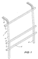
- An example of a frame constructed in accordance with a co-planar design is illustrated in figure 1. In this construction the side pillars 1 are constructed of three discrete parts; a
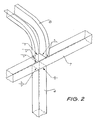
skirt portion 2; a central side pillar 3; and awindow pillar 4. Interposed between respective parts of the side pillars 1 are thecontinuous floor rail 5, the continuous waist rail 6 and thecontinuous cant rail 7 to which is welded the roof bow 8 which is in the form of a flanged open square channel. - A typical weld detail is shown in figure 2 which illustrates the roof-side frame joint of a structure utilizing coplanar joints. As can be seen, each discrete element requires either fillet or butt welding as required at each of the mating edges. Thus a considerable amount of time is required for welding of the total frame because of the number of discrete parts.
- Therefore to ameliorate this disadvantage and to improve joint efficiency by reducing stresses in the joints, the invention, in one broad form, comprises a vehicle frame structure having a plurality of continuous substantially vertical pillar members and continuous substantially horizontal rails, whereby said rails and said pillars are connected in an overlapping manner.
- In one embodiment the rails are welded to said pillars. Preferably both the rails and pillars are rectangular tubing.
- The invention will so be described by way of example with reference to the accompanying figures in which:
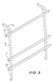
- Figure 3 illustrates a view of one bay of a vehicle using an embodiment of the present invention;
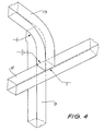
- Figure 4 illustrates a roof-side frame joint weld detail of the embodiment illustrated in figure 3;
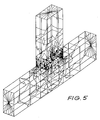
- Figure 5 shows a stress distribution diagram for a coplanar joint;
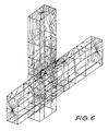
- Figure 6 shows a stress distribution diagram for an overlap joint;
- Figure 7 illustrates longitudinal loading fatigue tests for a coplanar and overlap joint;
- Figure 8 illustrates transverse loading fatigue tests for a coplanar and overlap joint; and
- Figure 9 illustrates an energy absorption comparison test for coplanar and overlap construction.
- As shown in figure 3
continuous side pillars 9 are used. Connected across them arecontinuous floor rails 10,continuous waist rails 11 andcontinuous cant rails 12, in a overlapping formation. The rails are preferably welded to the pillars. - A welding detail is shown in figure 4 whereby the roof bow 13 a hollow rectangular tube is welded to the
side pillar 9, extending beyond thecontinuous cant rail 12 and to thecontinuous cant rail 12 by appropriate fillet and square welds at the mating edges. - In the present invention optimal use is made of continuous elements; the only regions continuity is not used is because of other considerations, i.e. roof hatches, doorways, dictate that this is not the case. Generally then, the structure comprises virtually full vehicle length roof stringers, full vehicle length cant rails, full vehicle length waist (except for doorways), full vehicle length floor rails, (except for doorways) and full length floor rails to cant rail, side pillars.
- Because of requirements for crashworthiness the
roof bow 13, is not continuous with the side pillars. The specific overlap detail as shown in figure 4 helps absorb energy in rollover type deformations and improves fatigue resistance by transmitting loads in shear across the joint as opposed to loads being transmitted as normal forces on a diaphragming area in the case of the prior art coplanar design. Contour stress plots of the coplanar model are shown in figure 5 and for the overlap model are shown in figure 6 showing denser concentration of stresses in the coplanar model. The joints are loaded and restrained in identical methods and the stresses were 27 MPa for the coplanar joint and 22 MPa for the overlap joint, with the coplanar joint having a 22.7% increase in stress compared to the overlap joint for the same size rectangular section. - The use of the overlap design provides an improved resistance to fatigue loading as compared to coplanar design. Tests were carried out on the configurations shown in figures 7 and 8, to obtain evaluation of the two designs in longitudinal and transverse loading. As is shown, there is a life increase of more than 14 times for overlap design compared to coplanar design for longitudinal loading and a life increase of more than 4 times for transverse loading.
- Because of the particular usage of continuous members and roof bow joint construction, embodiments of the present invention show an increase in energy absorption for rollover as compared to conventional designs for vehicles; see figure 9.
- Thus because of the reduced number of welds required there is a reduction in construction time of approximately 15% for the construction of the present invention as compared to the traditional coplanar method. Further rectangular tubing of half the cross-section of that of the square tubing of the coplanar method can be used which results in a weight saving in the frame.
- In summary then, the following benefits of the lap philosophy over the coplanar philosopy are:
- (i) Improved durability of the structure.
- (ii) Reduced weight of structure because of fewer components.
- (iii) Fewer components with the following atttributes:
- (a) the components are less costly,
- (b) overall lower assembly time since there are fewer components to manufacture and weld.
- (iv) More crashworthy.
Claims (4)
1. A vehicle frame structure having a plurality of continuous substantially vertical pillar members and continuous substantially horizontal rails, whereby said rails and said pillars are connected in an overlapping manner.
2. A vehicle frame structure according to claim 1 wherein pillar members, and rails are rectangular tubing.
3. A vehicle frame structure according to claim 1 or 2 wherein said pillar members and rails are welded together.
4. A vehicle frame structure according to claim 3 when appended to claim 2 wherein each of said continuous substantially vertical rails extends above the topmost of said continuous substantially horizontal rails, and roof bow members near their free ends are welded in a face-to-face relationship to the portion of the respective continuous vertical rails which extend above the topmost rail, with the free ends of said roof bows being welded to the top surface of said topmost continuous substantially horizontal rails, and wherein continuous roof stringers are welded to the roof bows in overlapping relationship.
Applications Claiming Priority (2)
| Application Number | Priority Date | Filing Date | Title |
|---|---|---|---|
| AUPI772588 | 1988-04-08 | ||
| AU7725/88 | 1988-04-08 |
Publications (2)
| Publication Number | Publication Date |
|---|---|
| EP0336781A2 true EP0336781A2 (en) | 1989-10-11 |
| EP0336781A3 EP0336781A3 (en) | 1990-09-12 |
Family
ID=3773023
Family Applications (1)
| Application Number | Title | Priority Date | Filing Date |
|---|---|---|---|
| EP19890303500 Withdrawn EP0336781A3 (en) | 1988-04-08 | 1989-04-10 | Vehicle frame structure |
Country Status (3)
| Country | Link |
|---|---|
| EP (1) | EP0336781A3 (en) |
| AU (1) | AU3255489A (en) |
| NZ (1) | NZ228661A (en) |
Cited By (6)
| Publication number | Priority date | Publication date | Assignee | Title |
|---|---|---|---|---|
| US5449213A (en) * | 1993-05-26 | 1995-09-12 | Aluminum Company Of America | Movable body panel for a vehicle and related method |
| US6293618B1 (en) * | 1998-10-15 | 2001-09-25 | Honda Giken Kogyo Kabushiki Kaisha | Pillar joint structure for automotive vehicle |
| DE20018314U1 (en) * | 2000-10-26 | 2002-03-28 | Fahrtec Systeme Gmbh | Case module for motor vehicles |
| US6378444B1 (en) * | 1999-06-03 | 2002-04-30 | Alstom | Rail vehicle body, a rail vehicle, and corresponding assembly methods |
| US7341299B1 (en) * | 2006-09-06 | 2008-03-11 | Ford Global Technologies, Llc | Double cell crushable joint for automotive front end |
| GB2442305A (en) * | 2006-09-26 | 2008-04-02 | Ford Global Tech Llc | Tubular structural joint for automotive front end |
Citations (3)
| Publication number | Priority date | Publication date | Assignee | Title |
|---|---|---|---|---|
| FR897883A (en) * | 1943-05-06 | 1945-04-04 | Prototypes De Carrosseries Leg | Bodywork for road vehicles |
| FR1075456A (en) * | 1953-03-04 | 1954-10-18 | Metal frame assembly for fixed or rolling construction | |
| FR1124380A (en) * | 1955-05-17 | 1956-10-09 | Fr Carrosserie Gangloff Soc | Body framework, more particularly for public transport motor vehicles |
Family Cites Families (1)
| Publication number | Priority date | Publication date | Assignee | Title |
|---|---|---|---|---|
| OA00080A (en) * | 1964-05-09 | 1966-01-15 | Urbain Marchand Et Cie | Unbreakable welded assembly for bodywork suitable for tracks with corrugated sheet sections. |
-
1988
- 1988-04-08 AU AU32554/89A patent/AU3255489A/en not_active Abandoned
-
1989
- 1989-04-07 NZ NZ22866189A patent/NZ228661A/en unknown
- 1989-04-10 EP EP19890303500 patent/EP0336781A3/en not_active Withdrawn
Patent Citations (3)
| Publication number | Priority date | Publication date | Assignee | Title |
|---|---|---|---|---|
| FR897883A (en) * | 1943-05-06 | 1945-04-04 | Prototypes De Carrosseries Leg | Bodywork for road vehicles |
| FR1075456A (en) * | 1953-03-04 | 1954-10-18 | Metal frame assembly for fixed or rolling construction | |
| FR1124380A (en) * | 1955-05-17 | 1956-10-09 | Fr Carrosserie Gangloff Soc | Body framework, more particularly for public transport motor vehicles |
Cited By (8)
| Publication number | Priority date | Publication date | Assignee | Title |
|---|---|---|---|---|
| US5449213A (en) * | 1993-05-26 | 1995-09-12 | Aluminum Company Of America | Movable body panel for a vehicle and related method |
| US6293618B1 (en) * | 1998-10-15 | 2001-09-25 | Honda Giken Kogyo Kabushiki Kaisha | Pillar joint structure for automotive vehicle |
| US6378444B1 (en) * | 1999-06-03 | 2002-04-30 | Alstom | Rail vehicle body, a rail vehicle, and corresponding assembly methods |
| DE20018314U1 (en) * | 2000-10-26 | 2002-03-28 | Fahrtec Systeme Gmbh | Case module for motor vehicles |
| US7341299B1 (en) * | 2006-09-06 | 2008-03-11 | Ford Global Technologies, Llc | Double cell crushable joint for automotive front end |
| GB2442305A (en) * | 2006-09-26 | 2008-04-02 | Ford Global Tech Llc | Tubular structural joint for automotive front end |
| US7441819B2 (en) * | 2006-09-26 | 2008-10-28 | Ford Global Technologies, Llc | Tubular structural joint for automotive front end |
| GB2442305B (en) * | 2006-09-26 | 2011-03-02 | Ford Global Tech Llc | A tubular structural joint for automotive front end |
Also Published As
| Publication number | Publication date |
|---|---|
| AU3255489A (en) | 1989-10-12 |
| EP0336781A3 (en) | 1990-09-12 |
| NZ228661A (en) | 1991-06-25 |
Similar Documents
| Publication | Publication Date | Title |
|---|---|---|
| CA1265388A (en) | Centre beam railroad car | |
| US5655792A (en) | Composite trailer and van type container assembly using bi-metal materials | |
| US6134787A (en) | Method of producing a rail-bound rail vehicle for passenger transport | |
| EP2110291A2 (en) | Car body structure for a railway vehicle | |
| US11020676B2 (en) | Backbone rail for a roller coaster and roller coaster arrangement | |
| EP0336781A2 (en) | Vehicle frame structure | |
| CN104058009A (en) | Vehicle Body Rear Structure | |
| CN110027577A (en) | Aluminum honeycomb and aluminium sheet splicing drivers' cab and the rail vehicle with it | |
| CN107938508A (en) | A kind of HRP Orthotropic Steel Bridge Decks structure | |
| KR960007336A (en) | The body of a railway vehicle | |
| DE8125375U1 (en) | Lattice girder for the underground track and shaft expansion | |
| CN110605494B (en) | Detachable assembled steel box girder U rib structure and process | |
| CN106677062A (en) | Orthotropic bridge deck system structure with double girders and dense cross beams | |
| US2314979A (en) | Rail car | |
| US2171434A (en) | Beam-type housing structure | |
| DE102019126366A1 (en) | Car body element for a car body | |
| CN104590377B (en) | A kind of vehicle frame | |
| CN110027578B (en) | Cab roof structure, cab and rail train | |
| CN211592700U (en) | Flexible frame and have its vehicle | |
| DE904418C (en) | Self-supporting car body, especially for rail vehicles | |
| CN106644431B (en) | Fixing clamp for fatigue test of undercarriage | |
| CN204959578U (en) | PC track roof beam | |
| CN211922243U (en) | Pre-assembled steel box girder | |
| CN217260634U (en) | Forming device for long purlin structural member of airplane | |
| EP0100750B1 (en) | Arrangement of stiffening elements, especially in load carrying vehicles |
Legal Events
| Date | Code | Title | Description |
|---|---|---|---|
| PUAI | Public reference made under article 153(3) epc to a published international application that has entered the european phase |
Free format text: ORIGINAL CODE: 0009012 |
|
| AK | Designated contracting states |
Kind code of ref document: A2 Designated state(s): AT BE CH DE ES FR GB GR IT LI LU NL SE |
|
| PUAL | Search report despatched |
Free format text: ORIGINAL CODE: 0009013 |
|
| AK | Designated contracting states |
Kind code of ref document: A3 Designated state(s): AT BE CH DE ES FR GB GR IT LI LU NL SE |
|
| STAA | Information on the status of an ep patent application or granted ep patent |
Free format text: STATUS: THE APPLICATION IS DEEMED TO BE WITHDRAWN |
|
| 18D | Application deemed to be withdrawn |
Effective date: 19910514 |