EP0336591A2 - Schaltungsanordnung mit doppelter Abstimmung für die verteilt lokalisierte Kapazität von Empfangsspulen - Google Patents
Schaltungsanordnung mit doppelter Abstimmung für die verteilt lokalisierte Kapazität von Empfangsspulen Download PDFInfo
- Publication number
- EP0336591A2 EP0336591A2 EP89302658A EP89302658A EP0336591A2 EP 0336591 A2 EP0336591 A2 EP 0336591A2 EP 89302658 A EP89302658 A EP 89302658A EP 89302658 A EP89302658 A EP 89302658A EP 0336591 A2 EP0336591 A2 EP 0336591A2
- Authority
- EP
- European Patent Office
- Prior art keywords
- capacitance
- inductance
- portions
- circuit
- double tuned
- Prior art date
- Legal status (The legal status is an assumption and is not a legal conclusion. Google has not performed a legal analysis and makes no representation as to the accuracy of the status listed.)
- Granted
Links
- 239000003990 capacitor Substances 0.000 claims abstract description 11
- 239000000523 sample Substances 0.000 claims description 25
- 238000005481 NMR spectroscopy Methods 0.000 description 6
- 230000001939 inductive effect Effects 0.000 description 5
- 230000008878 coupling Effects 0.000 description 4
- 238000010168 coupling process Methods 0.000 description 4
- 238000005859 coupling reaction Methods 0.000 description 4
- 230000005540 biological transmission Effects 0.000 description 3
- 238000002955 isolation Methods 0.000 description 3
- OKTJSMMVPCPJKN-OUBTZVSYSA-N Carbon-13 Chemical compound [13C] OKTJSMMVPCPJKN-OUBTZVSYSA-N 0.000 description 2
- 239000004020 conductor Substances 0.000 description 2
- 230000005284 excitation Effects 0.000 description 2
- 238000002474 experimental method Methods 0.000 description 2
- 238000012545 processing Methods 0.000 description 2
- 238000004088 simulation Methods 0.000 description 2
- 230000003595 spectral effect Effects 0.000 description 2
- 230000001052 transient effect Effects 0.000 description 2
- 238000012935 Averaging Methods 0.000 description 1
- 238000004458 analytical method Methods 0.000 description 1
- 238000013459 approach Methods 0.000 description 1
- 238000013461 design Methods 0.000 description 1
- 238000005315 distribution function Methods 0.000 description 1
- 230000001747 exhibiting effect Effects 0.000 description 1
- 229910052739 hydrogen Inorganic materials 0.000 description 1
- 239000001257 hydrogen Substances 0.000 description 1
- 230000006698 induction Effects 0.000 description 1
- 230000001678 irradiating effect Effects 0.000 description 1
- 230000035772 mutation Effects 0.000 description 1
- 230000003534 oscillatory effect Effects 0.000 description 1
- 230000011218 segmentation Effects 0.000 description 1
- 230000009466 transformation Effects 0.000 description 1
- 238000004804 winding Methods 0.000 description 1
Images
Classifications
-
- G—PHYSICS
- G01—MEASURING; TESTING
- G01R—MEASURING ELECTRIC VARIABLES; MEASURING MAGNETIC VARIABLES
- G01R33/00—Arrangements or instruments for measuring magnetic variables
- G01R33/20—Arrangements or instruments for measuring magnetic variables involving magnetic resonance
- G01R33/28—Details of apparatus provided for in groups G01R33/44 - G01R33/64
- G01R33/32—Excitation or detection systems, e.g. using radio frequency signals
- G01R33/36—Electrical details, e.g. matching or coupling of the coil to the receiver
- G01R33/3628—Tuning/matching of the transmit/receive coil
- G01R33/3635—Multi-frequency operation
Definitions
- the invention is related to RF probe circuits in the context of nuclear magnetic resonance apparatus and more particularly, with such apparatus requiring a double tuned probe.
- a double tuned circuit is one which exhibits a resonant condition for at least two discrete frequencies.
- NMR nuclear magnetic resonance
- a variation of such an arrangement is the concurrent excitation or observation of chemically distinct samples where one such sample is a control for instrumental purposes, as in establishing a field frequency lock, while the second sample is under examination.
- An example of this may be found in U.S. 3,434,043.
- a similar circumstance is the desire to concurrently excite selected different nuclei for acquisition of corresponding spectral response.
- a double tuned circuit ordinarily utilizes a single inductor common to two resonant circuits.
- Each circuit in such an arrangement is separately tuned and impedance matched to its respective RF source (or sink).
- What is necessary for this arrangement is an isolation element between the high frequency and low frequency sources.
- Double tuned circuits are known which employ a cable of length ⁇ /4 (at the high frequency) to provide such isolation. See, for example, Stoll, Vega and Vaughan, Rev. Sci. Inst., V. 48, pp. 800-803 (1977).
- Balanced circuits exhibiting electrical (e.g., RF) symmetry are also known for the purpose of supporting double tuned apparatus.
- Such circuits exhibit the virtue that a symmetry plane (or other surface) is defined which has a property of electrical neutrality, e.g., a virtual ground.
- Inductive elements in RF probe circuits are known to include "split inductors" such as taught in the work of Alderman and Grant, J. Mag. Res., V. 36, pp. 447-451 (1979).
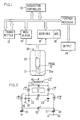
- FIG. 1 Portions of a typical NMR data acquisition instrument are schematically illustrated on FIG. 1.
- An acquisition/control processor 10 communicates with an RF transmitter 12, modulator 14 and receiver 16, including analog-to-digital converter 18 and a further processor 20.
- the modulated RF power irradiates an object (not shown) in a magnetic field 21 through a probe assembly 22 and the response of the object is intercepted by probe 22 communicating with receiver 16.
- the response typically takes the form of a transient oscillatory signal, or free induction decay.
- This transient waveform is sampled at regular intervals and samples are digitized in ADC 18.
- the digitized time domain waveform is then subject to further processing in processor 20.
- the nature of such processing may include averaging a time domain waveform with a number of similar such waveforms, and transformation of the average time domain waveform to the frequency domain yields a spectral distribution function directed to output device 24.
- the latter may take on any of a number of identities for the display of further analysis and data.
- the magnetic field 21 which polarizes the sample is established by an appropriate means indicated in FIG. 1 in a cryostat 23 for maintaining a superconducting phase in a solenoid, not shown.
- the cryostat comprises a bore 23a in which the probe and sample are housed at room temperature.
- FIG. 2 there is shown a circuit representative of a double tuned, balanced, split inductance RF probe suitable for experiments requiring the double tuned property in a sample volume V defined in a geometric sense between the inductances L1 (a) and L1 (b) .
- the circuit arrangement permits the low frequency RF applied at 32 to circulate through L2 (a) thence over the loop comprising L1 (b) , L2 (c) , L1 (a) and L2 (b) to ground.
- high frequency RF is applied at 36 and propagates in the inductive loop L1 (a) and L1 (b) and the inductance L2 represents parallel current paths.
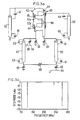
- FIG. 3a there is shown a preferred embodiment for realizing the desired circuit.
- a pair of H shaped conductors 40 and 42 are arranged with arms and legs and configured to form a body of cylindrical symmetry. The central portion of the H shaped member is parallel with the axis of symmetry. The corresponding arms are electrically connected by chip capacitors 44 and 45 and the adjacent legs are similarly joined by chip capacitors 46 and 47.
- the H shaped conductors 40 and 42 form a pair of inductive elements (implementing inductors L1 (a) and L1 (b) ) and the coupling coefficient of these inductors is close to unity. Each inductor is connected at one end to a resonant structure which presents a relatively high impedance to the selected high frequency.
- each of the H shaped members 40 and 42 are connected respectively to similar resonance structures 60 and 62 with similar properties. These implement the trap inductor L2 (c) .
- the low frequency excitation is delivered from connector 64 through matching capacitor 65 to resonator 60.
- Corresponding resonator 62 is coupled through capacitor 68 to ground and the resonators are capacitively coupled through variable capacitor 69.
- High frequency RF is applied at connector 66 through capacitor 67 to the inductive element 42 and in parallel with capacitor 56 to ground.
- the resonant structures 50, 52, 60 and 62 may be realized by coaxial cables of length not to exceed ⁇ /2. Capacitances 49, 51, 61 and 65, here expressly shown, serve to tune the transmission line and thus adjust the effective length of the transmission line.
- FIG. 3b shows the simulated frequency response for the circuit of FIG. 3a for the circuit components as below:
- Label Value Label Value 40 61 nh 54,56 .109 pf 42 61 nh 61,63 19.29 pf 44,45,46,57 1.125 pf 49,51,67 2.16 pf 50,52 .0625 meters 65,68 3.43 pf 60,62
- Z o 77 ⁇ 69 9.09 pf atten: .04db
- spurious resonances are found in this example.
- the location of such artifacts depends upon details of circuit elements. While characterized as "spurious", such artifacts reflect reactive couplings which may be analyzed as comprising additional (unbalanced) circuit loop(s) and characterized by corresponding resonant behavior. Thus, where it is desirable to obtain further discrete resonant behavior, such response may be tailored for this purpose.
- the circuit is balanced and is characterized by a virtual ground plane such that it is unnecessary to establish a real ground at capacitances 54 and 56 (these capacitances may be simply interconnected). The presence or absence of real ground at such points on the virtual ground symmetry axis will affect the character of the spurious resonances.
- the double tuned probe of the invention exhibits a relative efficiency of 0.734 at 400 MHz and 0.870 at 100 MHz.
- a particularly useful perspective for considering the effectiveness of a probe may be gained by comparing the pulse duration required at 1 watt input to obtain a 90° mutation of a resonant nuclear spin system.
- the reference coil For protons at 400 MHz, the reference coil requires 19.2 ⁇ sec and the subject double tuned probe requires 26.2 ⁇ sec.
- the reference coil For C13 at 100 MHz, the reference coil requires 54.1 ⁇ sec and the subject double tuned probe requires 62.2 ⁇ sec.
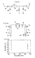
- a further realistic performance comparison may be had with respect to a model single inductor double tuned balanced circuit such as shown in FIG. 4a.
- the parameters of the model circuit are adjusted to obtain the same (simulated) performance (FIG. 4b) as obtained for the circuit of FIG. 3a.
- the resonant frequencies are fixed and the single inductor 70 of the model circuit presents the same total inductance as the use of split inductors 40 and 42.
- the resonant RF impedances corresponding to resonators 60 and 62 are furnished by respective resonators 72 and 76 with corresponding tuning capacitances 74 and 78.
- the resonators 72 and 76 are necessarily twice the length as required for the performance of FIG. 3a for otherwise identical cable.
- the model may also be compared to the reference coil in the same manner as was the double tuned probe of the invention.
- the relative efficiency for the model at 400 MHz is 0.733 and at 100 MHz is 0.893.
- the double tuned probe of the invention closely approaches the performance of a model (single inductor) double tuned probe.
- FIG. 5 shows an elementary example of a double tuned circuit with transmission line isolation between high and low frequency channels.
- the tuning capacitances 92 and 94 for high frequency and low frequency channels are respectively 4.56 pf. and 27.31 pf.
- Matching capacitances 96 and 98 for high frequency and low frequency channels are respectively 0.63 pf. and 3.12 pf.
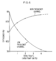
- FIG. 6 is calculated for circuits operating at a high frequency of 200 MHz and a low frequency of 50 MHz.
- the efficiency for both high and low frequency channels is shown for each of the circuits of FIGS. 3a, 4a and 5 as a function of total trap inductance. For any one of these circuits there is a practical limit to the achievable trap inductance. For coaxial elements discussed herein, this limit occurs at ⁇ /2.
- L 4 arbitrary units
- the extension of the present invention to higher high frequency efficiency is achievable through additional segmentation of the inductance L1, (the NMR observe coil) to a further number of segments with concomitant additional trap inductance.
- the use of shielded coaxial cables for trap inductors (50 and 52) and inductances 60 and 62 contribute two very useful mechanical design advantages.
- Axial symmetry is more easily preserved in an axial structure. This is a frequent choice of geometry, e.g. the symmetry axis coinciding with the polarizing magnetic field and the mechanical structural axis of the magnet.
- the implementation of FIG. 3a is advantageous because the balanced nature of the circuit permits the circuit to be physically distributed along the symmetry axis of the magnet.
- Shielded coaxial cables also minimize strong inductive couplings between, for example, the trap inductances L2 (c) and L1 (a) or L1 (b) . (See FIG. 2).
Landscapes
- Physics & Mathematics (AREA)
- Condensed Matter Physics & Semiconductors (AREA)
- General Physics & Mathematics (AREA)
- Magnetic Resonance Imaging Apparatus (AREA)
- Geophysics And Detection Of Objects (AREA)
Applications Claiming Priority (2)
| Application Number | Priority Date | Filing Date | Title |
|---|---|---|---|
| US07/179,014 US4833412A (en) | 1988-04-08 | 1988-04-08 | Double tuned circuit for distributed lumped capacitance observe coils |
| US179014 | 1988-04-08 |
Publications (3)
| Publication Number | Publication Date |
|---|---|
| EP0336591A2 true EP0336591A2 (de) | 1989-10-11 |
| EP0336591A3 EP0336591A3 (de) | 1991-01-02 |
| EP0336591B1 EP0336591B1 (de) | 1995-12-20 |
Family
ID=22654873
Family Applications (1)
| Application Number | Title | Priority Date | Filing Date |
|---|---|---|---|
| EP89302658A Expired - Lifetime EP0336591B1 (de) | 1988-04-08 | 1989-03-17 | Schaltungsanordnung mit doppelter Abstimmung für die verteilt lokalisierte Kapazität von Empfangsspulen |
Country Status (4)
| Country | Link |
|---|---|
| US (1) | US4833412A (de) |
| EP (1) | EP0336591B1 (de) |
| JP (1) | JP2748016B2 (de) |
| DE (1) | DE68925143T2 (de) |
Cited By (1)
| Publication number | Priority date | Publication date | Assignee | Title |
|---|---|---|---|---|
| US7132829B2 (en) | 2005-01-18 | 2006-11-07 | Varian, Inc. | NMR RF coils with improved low-frequency efficiency |
Families Citing this family (21)
| Publication number | Priority date | Publication date | Assignee | Title |
|---|---|---|---|---|
| US4916418A (en) * | 1989-03-31 | 1990-04-10 | Varian Associates, Inc. | Double tuned bird cage coil |
| US5038105A (en) | 1990-02-09 | 1991-08-06 | Spectroscopy Imaging Systems Corporation | Series/parallel double-tuned NMR coils |
| US5036426A (en) * | 1990-02-22 | 1991-07-30 | Board Of Regents, The University Of Texas System | Method and apparatus for tuning and matching an NMR coil |
| US5057778A (en) * | 1990-03-29 | 1991-10-15 | Spectroscopy Imaging Systems Corporation | Double tuned nmr coils |
| US5166621A (en) * | 1990-10-26 | 1992-11-24 | Spectroscopy Imaging Systems Corporation | Multi-resonant nmr coils |
| US5162739A (en) * | 1991-04-05 | 1992-11-10 | F. David Doty | Balanced multi-tuned high-power broadband coil for nmr |
| JP2911268B2 (ja) | 1991-10-02 | 1999-06-23 | 日本電子株式会社 | 核磁気共鳴プローブ複同調回路 |
| DE69321891T2 (de) * | 1992-07-14 | 1999-08-05 | Varian Associates, Inc., Palo Alto, Calif. | Abstimmbare Hochfrequenz-Sonde für magnetische Kernresonanz-Spektroskopie-Untersuchungen und Abstimmungsverfahren |
| US5412322A (en) * | 1993-06-24 | 1995-05-02 | Wollin Ventures, Inc. | Apparatus and method for spatially ordered phase encoding and for determining complex permittivity in magnetic resonance by using superimposed time-varying electric fields |
| JP2687883B2 (ja) * | 1994-07-06 | 1997-12-08 | 日本電気株式会社 | リング伝送路におけるプロテクション情報管理システム |
| US6489768B1 (en) | 2000-10-23 | 2002-12-03 | Varian, Inc. | Superconductive networks to optimize multiply tuned NMR coils |
| AU2002353183A1 (en) * | 2001-12-31 | 2003-07-24 | The Johns Hopkins University School Of Medicine | Mri tunable antenna and system |
| DE10361347B4 (de) * | 2003-12-16 | 2012-01-19 | Bruker Biospin Gmbh | Probenkopf für Kernresonanzmessungen |
| US6933725B2 (en) * | 2004-01-16 | 2005-08-23 | Bruker Biospin Corporation | NMR probe circuit for generating close frequency resonances |
| FR2871892B1 (fr) * | 2004-06-18 | 2006-09-01 | Bruker Biospin Sa Sa | Circuit d'alimentation d'une bobine et sonde et spectrometre rmn comportant un tel circuit |
| JP5315556B2 (ja) * | 2009-09-08 | 2013-10-16 | 株式会社 Jeol Resonance | Nmr検出器 |
| TWI474008B (zh) * | 2013-07-15 | 2015-02-21 | Mpi Corp | A signal path switching device and a probe card using a signal path switching device |
| JP6677745B2 (ja) | 2015-04-15 | 2020-04-08 | 日本電子株式会社 | 磁気結合の高分解能核磁気共鳴プローブおよび使用法 |
| US10908239B1 (en) | 2020-04-14 | 2021-02-02 | Jeol Ltd. | Broad band inductive matching of a nuclear magnetic resonance circuit using inductive coupling |
| US11726152B1 (en) | 2022-08-26 | 2023-08-15 | Jeol Ltd. | Solid sample magnetic coupling high resolution nuclear magnetic resolution probe and method of use |
| US12422508B1 (en) | 2022-08-26 | 2025-09-23 | Jeol Ltd. | Sliding band capacitor inductive coupling in a low temperature nuclear magnetic resonance probe and methods of use |
Family Cites Families (11)
| Publication number | Priority date | Publication date | Assignee | Title |
|---|---|---|---|---|
| US4446431A (en) * | 1981-08-24 | 1984-05-01 | Monsanto Company | Double-tuned single coil probe for nuclear magnetic resonance spectrometer |
| US4641097A (en) * | 1984-05-10 | 1987-02-03 | General Electrtic Company | Elliptical cross-section slotted-tube radio-frequency resonator for nuclear magnetic resonance imaging |
| US4740751A (en) * | 1984-08-16 | 1988-04-26 | Picker International, Inc. | Whole body MRI resonator |
| US4594566A (en) * | 1984-08-30 | 1986-06-10 | Advanced Nmr Systems, Inc. | High frequency rf coil for NMR device |
| US4725780A (en) * | 1984-10-19 | 1988-02-16 | Mitsubishi Denki Kabushiki Kaisha | RF field generator and detector |
| US4737715A (en) * | 1985-02-14 | 1988-04-12 | Jeol Ltd. | Coil system for nuclear magnetic resonance spectrometer probe |
| US4641098A (en) * | 1985-03-15 | 1987-02-03 | Doty Scientific, Inc. | Parallel single turn saddle resonator for nuclear magnetic resonance signal reception |
| US4720680A (en) * | 1986-02-18 | 1988-01-19 | Mitsubishi Denki Kabushiki Kaisha | Adjustable radio frequency coil for nuclear magnetic resonance imaging |
| US4755756A (en) * | 1986-02-18 | 1988-07-05 | Mitsubishi Denki Kabushiki Kaisha | Radio frequency coil for nuclear magnetic resonance imaging |
| IL77937A (en) * | 1986-02-20 | 1989-03-31 | Elscint Ltd | Hybrid resonator |
| US4752736A (en) * | 1986-07-22 | 1988-06-21 | The Regents Of The University Of California | Center fed QD MRI RF coil |
-
1988
- 1988-04-08 US US07/179,014 patent/US4833412A/en not_active Expired - Lifetime
-
1989
- 1989-03-17 EP EP89302658A patent/EP0336591B1/de not_active Expired - Lifetime
- 1989-03-17 DE DE68925143T patent/DE68925143T2/de not_active Expired - Lifetime
- 1989-04-07 JP JP1087138A patent/JP2748016B2/ja not_active Expired - Lifetime
Cited By (2)
| Publication number | Priority date | Publication date | Assignee | Title |
|---|---|---|---|---|
| US7132829B2 (en) | 2005-01-18 | 2006-11-07 | Varian, Inc. | NMR RF coils with improved low-frequency efficiency |
| WO2006078415A3 (en) * | 2005-01-18 | 2007-03-29 | Varian Inc | Nmr rf coils with improved low-frequency efficiency |
Also Published As
| Publication number | Publication date |
|---|---|
| EP0336591B1 (de) | 1995-12-20 |
| DE68925143D1 (de) | 1996-02-01 |
| JPH0213871A (ja) | 1990-01-18 |
| US4833412A (en) | 1989-05-23 |
| DE68925143T2 (de) | 1996-05-15 |
| JP2748016B2 (ja) | 1998-05-06 |
| EP0336591A3 (de) | 1991-01-02 |
Similar Documents
| Publication | Publication Date | Title |
|---|---|---|
| EP0336591B1 (de) | Schaltungsanordnung mit doppelter Abstimmung für die verteilt lokalisierte Kapazität von Empfangsspulen | |
| US5243289A (en) | Multiply-tuned probe for magnetic resonance imaging or spectroscopy | |
| US4916398A (en) | Efficient remote transmission line probe tuning for NMR apparatus | |
| US4594566A (en) | High frequency rf coil for NMR device | |
| EP0522037B1 (de) | Spulen für die magnetische kernresonanz mit doppelter abstimmung | |
| US5424645A (en) | Doubly broadband triple resonance or quad resonance NMR probe circuit | |
| US7292038B2 (en) | Double-balanced double-tuned CP birdcage with similar field profiles | |
| US5166621A (en) | Multi-resonant nmr coils | |
| US5038105A (en) | Series/parallel double-tuned NMR coils | |
| Stoll et al. | Simple single‐coil double resonance NMR probe for solid state studies | |
| EP0339723A1 (de) | Magnetischer Resonanzapparat mit entkoppelten HF-Spulen | |
| US5162739A (en) | Balanced multi-tuned high-power broadband coil for nmr | |
| Fitzsimmons et al. | A comparison of double‐tuned surface coils | |
| US20230078150A1 (en) | Double-resonant coil, array of double-resonant coils, and use thereof | |
| EP0312586B1 (de) | Regelung der pseudo-resonanzen für magnetische kernresonanz-empfangsspulen | |
| US4731584A (en) | Magnetic resonance probe for operation at frequencies above self resonance | |
| Dürr et al. | A dual‐frequency circularly polarizing whole‐body MR antenna for 69/170 MHz | |
| Tang et al. | Double-resonance circuit for nuclear magnetic resonance spectroscopy |
Legal Events
| Date | Code | Title | Description |
|---|---|---|---|
| PUAI | Public reference made under article 153(3) epc to a published international application that has entered the european phase |
Free format text: ORIGINAL CODE: 0009012 |
|
| AK | Designated contracting states |
Kind code of ref document: A2 Designated state(s): CH DE GB LI NL |
|
| PUAL | Search report despatched |
Free format text: ORIGINAL CODE: 0009013 |
|
| AK | Designated contracting states |
Kind code of ref document: A3 Designated state(s): CH DE GB LI NL |
|
| 17P | Request for examination filed |
Effective date: 19901227 |
|
| 17Q | First examination report despatched |
Effective date: 19921215 |
|
| GRAA | (expected) grant |
Free format text: ORIGINAL CODE: 0009210 |
|
| AK | Designated contracting states |
Kind code of ref document: B1 Designated state(s): CH DE GB LI NL |
|
| REG | Reference to a national code |
Ref country code: GB Ref legal event code: 746 Effective date: 19951229 |
|
| REF | Corresponds to: |
Ref document number: 68925143 Country of ref document: DE Date of ref document: 19960201 |
|
| REG | Reference to a national code |
Ref country code: CH Ref legal event code: NV Representative=s name: BOVARD AG PATENTANWAELTE |
|
| PLBE | No opposition filed within time limit |
Free format text: ORIGINAL CODE: 0009261 |
|
| STAA | Information on the status of an ep patent application or granted ep patent |
Free format text: STATUS: NO OPPOSITION FILED WITHIN TIME LIMIT |
|
| 26N | No opposition filed | ||
| PGFP | Annual fee paid to national office [announced via postgrant information from national office to epo] |
Ref country code: NL Payment date: 19980223 Year of fee payment: 10 |
|
| PGFP | Annual fee paid to national office [announced via postgrant information from national office to epo] |
Ref country code: CH Payment date: 19990309 Year of fee payment: 11 |
|
| PG25 | Lapsed in a contracting state [announced via postgrant information from national office to epo] |
Ref country code: NL Free format text: LAPSE BECAUSE OF NON-PAYMENT OF DUE FEES Effective date: 19991001 |
|
| NLV4 | Nl: lapsed or anulled due to non-payment of the annual fee |
Effective date: 19991001 |
|
| PG25 | Lapsed in a contracting state [announced via postgrant information from national office to epo] |
Ref country code: LI Free format text: LAPSE BECAUSE OF NON-PAYMENT OF DUE FEES Effective date: 20000331 Ref country code: CH Free format text: LAPSE BECAUSE OF NON-PAYMENT OF DUE FEES Effective date: 20000331 |
|
| REG | Reference to a national code |
Ref country code: CH Ref legal event code: PL |
|
| REG | Reference to a national code |
Ref country code: GB Ref legal event code: 732E |
|
| REG | Reference to a national code |
Ref country code: GB Ref legal event code: IF02 |
|
| PGFP | Annual fee paid to national office [announced via postgrant information from national office to epo] |
Ref country code: GB Payment date: 20080327 Year of fee payment: 20 |
|
| PGFP | Annual fee paid to national office [announced via postgrant information from national office to epo] |
Ref country code: DE Payment date: 20080430 Year of fee payment: 20 |
|
| REG | Reference to a national code |
Ref country code: GB Ref legal event code: PE20 Expiry date: 20090316 |
|
| PG25 | Lapsed in a contracting state [announced via postgrant information from national office to epo] |
Ref country code: GB Free format text: LAPSE BECAUSE OF EXPIRATION OF PROTECTION Effective date: 20090316 |