EP0336477A1 - Method of determining drill bit wear - Google Patents
Method of determining drill bit wear Download PDFInfo
- Publication number
- EP0336477A1 EP0336477A1 EP89200745A EP89200745A EP0336477A1 EP 0336477 A1 EP0336477 A1 EP 0336477A1 EP 89200745 A EP89200745 A EP 89200745A EP 89200745 A EP89200745 A EP 89200745A EP 0336477 A1 EP0336477 A1 EP 0336477A1
- Authority
- EP
- European Patent Office
- Prior art keywords
- cone
- frequency
- bit
- spectrum
- rotation
- Prior art date
- Legal status (The legal status is an assumption and is not a legal conclusion. Google has not performed a legal analysis and makes no representation as to the accuracy of the status listed.)
- Granted
Links
Images


Classifications
-
- E—FIXED CONSTRUCTIONS
- E21—EARTH DRILLING; MINING
- E21B—EARTH DRILLING, e.g. DEEP DRILLING; OBTAINING OIL, GAS, WATER, SOLUBLE OR MELTABLE MATERIALS OR A SLURRY OF MINERALS FROM WELLS
- E21B12/00—Accessories for drilling tools
- E21B12/02—Wear indicators
-
- E—FIXED CONSTRUCTIONS
- E21—EARTH DRILLING; MINING
- E21B—EARTH DRILLING, e.g. DEEP DRILLING; OBTAINING OIL, GAS, WATER, SOLUBLE OR MELTABLE MATERIALS OR A SLURRY OF MINERALS FROM WELLS
- E21B44/00—Automatic control systems specially adapted for drilling operations, i.e. self-operating systems which function to carry out or modify a drilling operation without intervention of a human operator, e.g. computer-controlled drilling systems; Systems specially adapted for monitoring a plurality of drilling variables or conditions
-
- G—PHYSICS
- G01—MEASURING; TESTING
- G01H—MEASUREMENT OF MECHANICAL VIBRATIONS OR ULTRASONIC, SONIC OR INFRASONIC WAVES
- G01H1/00—Measuring characteristics of vibrations in solids by using direct conduction to the detector
- G01H1/003—Measuring characteristics of vibrations in solids by using direct conduction to the detector of rotating machines
-
- G—PHYSICS
- G05—CONTROLLING; REGULATING
- G05B—CONTROL OR REGULATING SYSTEMS IN GENERAL; FUNCTIONAL ELEMENTS OF SUCH SYSTEMS; MONITORING OR TESTING ARRANGEMENTS FOR SUCH SYSTEMS OR ELEMENTS
- G05B19/00—Programme-control systems
- G05B19/02—Programme-control systems electric
- G05B19/18—Numerical control [NC], i.e. automatically operating machines, in particular machine tools, e.g. in a manufacturing environment, so as to execute positioning, movement or co-ordinated operations by means of programme data in numerical form
- G05B19/406—Numerical control [NC], i.e. automatically operating machines, in particular machine tools, e.g. in a manufacturing environment, so as to execute positioning, movement or co-ordinated operations by means of programme data in numerical form characterised by monitoring or safety
- G05B19/4065—Monitoring tool breakage, life or condition
Landscapes
- Engineering & Computer Science (AREA)
- Geology (AREA)
- Life Sciences & Earth Sciences (AREA)
- Physics & Mathematics (AREA)
- Mining & Mineral Resources (AREA)
- Geochemistry & Mineralogy (AREA)
- Fluid Mechanics (AREA)
- General Life Sciences & Earth Sciences (AREA)
- Environmental & Geological Engineering (AREA)
- General Physics & Mathematics (AREA)
- Human Computer Interaction (AREA)
- Manufacturing & Machinery (AREA)
- Automation & Control Theory (AREA)
- Mechanical Engineering (AREA)
- Earth Drilling (AREA)
- Measurement Of Mechanical Vibrations Or Ultrasonic Waves (AREA)
- Drilling Tools (AREA)
Abstract
Description
- The invention relates to the determination of the state of wear of a drill bit which is used at the lower end of a drill string for drilling a hydrocarbon or geothermal well. In particular, the invention relates to a method of determining the state of wear of the drill bit by detecting and analysing the vibrations produced by the drill bit when drilling.
- When drilling a borehole in the earth either for the search of hydrocarbons or for geothermal purposes, a drill string comprising drill pipes, drill collars and a drill bit, is rotated from the surface to drill the wellbore. Roller cone bits are widely used. They have cone shaped steel devices called cones that are free to turn as the bit rotates. Most roller cone bits have three cones although some have two and some have four. Each cone has cutting elements which are circumferential rows of teeth extending from each cone. The cutting elements are either steel teeth which are machined as part of the cone or sintered tungsten carbide teeth which are pressed into holes drilled in the cone surfaces. The geometry of a bit, and more particularly of its cones, is such that when the bit is rotated, the cones rotate, the teeth having a combined rolling and gouging action which drills the formation in contact with the drill bit. As the drilling proceeds, teeth are prone to wear. Exceptionally, they may break. The bearings of the cones are also subject to wear.
- The length of time that the drill bit can be used before it becomes excessively worn depends on a variety of factors such as the hardness and composition of the rock and the drill string weight that the operator places on the drill bit. The drill bit should be replaced when its rate of penetration has diminished to an unacceptable level or when torque values in rotating the drill string exceed an acceptable limit. The drill bit must also be replaced in case of a tooth break or a cone bearing failure. In order to avoid the cost of retrieving lost cones from the well bore or to avoid drilling with a worn out bit, the drillers tend to pull out the drill string after a certain drilling period although the drill bit is still working satisfactorily. Pulling out the drill string and tripping it in again with a new drill bit is a time consuming and costly operation. In order to maximise the drilling operation, it would be a significant advantage to obtain information regarding tooth wear and cone or tooth failure. With such information each drill bit could be used to the full extent of its useful life.
- As teeth bite against the rock one after another, they generate noise or vibration with frequency components determined by the weight at which teeth successively encounter the rock. Various methods have already been proposed to determine the working state of the bit by recording and analysing the vibrations generated by the drill bit.
- It is proposed in GB 2,179,736 A to obtain the frequency spectrum of the vibrational signal, by processing it through a Fourier transform. The frequency spectrum has been found to include various significant peaks which pertain to different tooth rows of the bit. Peak frequencies tend to increase as teeth wear, because the mean rate or rotation of a cutter (normalised relative to bit speed) tends to increase. Therefore the shift of peak frequencies give useful information on wear and hence whether it is yet time to pull out the drill string. Furthermore, abrupt changes in the form of the frequency spectrum are indicative of abrupt occurrences at the bit such as loss of a tooth. This may lead to the appearance of a new peak as an unbroken tooth is forced to take over the work previously done by the broken tooth. Loss of frequency peaks indicate that a wheel has stuck or is clogged by a ductile rock. However, the success of the method is limited to instances where it is possible to track the position of specific spectral peaks.
- In accordance with another method described in GB 1,330,191, the extent of wear of the drilling bit is determined by selecting at least one frequency band in the vibration spectrum and by measuring the average amplitude of the signal in the frequency band. In one embodiment, one frequency band is selected centred on the second harmonic of the maximum amplitude frequency and a second band is selected which is centred on the frequency between the second and third harmonic. The ratio between the average amplitudes of the vibrations in these bands is calculated, a ratio of more than two showing that the tool is new and a ratio of about one showing that it is worn.
- US reissue patent 28,436 relates to a method of determining bit damage by monitoring at the surface the rotary torque of the drill string for characteristic oscillations, the oscillations having a frequency not more than twice and not less than half the expected frequency of torsional oscillations of the drill string. In addition, the monitored oscillations have an amplitude in excess of the amplitude of any oscillations produced by rotation of an undamaged bit.
- US patent 2,985,829 relates to a method of determining the rate of bit rotation by detecting and interpreting vibrations at the surface. By demodulating and filtering the vibration signals, most of the frequency components (and therefore harmonics) different from the bit frequency are eliminated. In addition, the described system is based on the wrong assumption that there is a fixed relation between the speed of a bit and associated roller cones.
- The above described techniques have not given full satisfactory results. Therefore a need exists for a method to detect the working conditions of a drill bit, the wear of its teeth or of a cone bearing or a tooth break.
- Accordingly, the present invention proposes a method of determining the state of wear of a multicone drill bit fixed at the lower end of a drill string for drilling a borehole in the earth, wherein vibrations generated by the working drill bit are detected and converted into a time oscillatory signal from which a frequency spectrum is derived, the periodicity of the frequency spectrum is extracted, the rate of rotation of at least one cone is determined from said periodicity and the state of wear of the drill bit is derived from said rate of cone rotation. The frequency spectrum is advantageously normalized relative to the rate of bit rotation. The oscillatory signal represents the variation in amplitude of the vertical or torsional force applied to the drill bit. The frequency or frequencies generated by the pump injecting drilling mud into the drill string is or are advantageously detected and removed from the frequency spectrum. For that purpose, the mud pressure variations are detected and converted into a pressure signal from which a frequency spectrum is derived, the frequency or frequencies generated by the pump are identified and the frequency spectrum of the vibration oscillatory signal is filtered so as to remove said frequency or frequencies.
- In accordance with one embodiment, the range of possible rates of cone rotation is determined relative to the rate of bit rotation, the peak of highest amplitude in the frequency spectrum is identified within said range and the rate of cone rotation is determined from said peak position in the spectrum.
- In accordance with a further embodiment, a set of harmonics in the frequency spectrum is given prominence by determining the fundamental frequency in the set of harmonics and the rate of cone rotation is derived from said fundamental frequency. The cepstrum of the frequency spectrum can be computed, the peak of maximum amplitude selected from the cepstrum and the rate of cone rotation derived from the position of said peak in the cepstrum. Alternatively, compressed spectra are obtained by compressing the frequency axis of the frequency spectra by integer values, the compressed spectra are multiplied together so as to obtain an harmonic-enhanced spectrum, the fundamental frequency of said harmonic-enhanced spectrum is determined and the rate of cone rotation is derived from said fundamental frequency.
- The invention will be more fully described with reference to the accompanying drawings, in which:
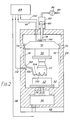
- Figure 1 shows schematically the equipment used at the surface on drilling rig to detect and interpret the vibrations generated by the drill bit downhole.
- Figure 2 is an elevational view of the equipment used in the laboratory to detect and measure vibrations generated by a drill bit drilling a rock sample.
- Figure 3 is a plot showing the vertical force on the 19-toothed row as a function of angle for
cone 3 of a drill bit for a new and partially worn cone. - Figure 4 shows the power spectra normalised to the cone rotation rate obtained from Figure 3 data.
- Figure 5 shows plots of the weight on bit power spectra for a new and worn bit.
- Figure 6 is a flow chart for a cone speed bit wear diagnostic.
- Figure 7 are cepstra derived from the power spectra shown in Figure 5.
- Figure 8 shows a comparison of original (Figure 8a) and harmonically enhanced (Figure 8b) spectra obtained from the drilling machine of Figure 2 for a worn bit.
- Figure 9 is a plot showing the actual cone speeds measured with the drilling machine shown on Figure 2, for various wear states.
- Figure 1 is a schematic view of the equipment which can be used to measure vibrations on an oil drilling rig. The derrick shown in Figure 1 comprising a
mast 10 standing on therig floor 12 and equipped with alift system 14, on which is suspended adrill string 16 carrying at its lower end adrill bit 18 for drilling awell 20. Thelifting system 14 comprises a crown block (not represented) fixed to the top of themast 10 and a verticallymobile travelling block 22 to which is attached ahook 24. Thedrill string 16 can be suspended onhook 24 via aninjection head 26 connected by aflexible hose 28 to a mud pump which makes it possible to circulate into thewell 20 to a drilling mud from a mud point. Thedrill string 16 comprises adriving rod 30, or kelly, and is formed frompipes 32 joined end to end by screwing. The drill string is rotated by the rotary table 34. The vibration signals generated by thedrill bit 18 can be detected either at the surface or downhole. When the detection is made at the surface, the equipment comprises atorque meter 36 fixed between the rotary table 34 and thekelly bushing 38.Torque meter 36 measures the torsional force, or torque (TOR), applied to thedrill string 16. It comprises anantenna 40 to transmit the torque signal to a receivingantenna 42 of a data acquisition andprocessing system 44. Thetorque meter 36 is preferably of the type described in US patent 4,471,663. The vertical force applied on the drill string, or weight on bit (WOB), is measured by twoload pins injection head 26 to thehook 50, itself hung on thehook 24. The load pins comprise strain gauges which are connected by theelectrical cable 52 to ajunction box 54 which is itself connected to the data acquisition andprocessing unit 44 via acable 56. These load pins and the torque meter are commercially available. Accelerometers could also be used in addition to the torque meter and load pins, in order to measure accelerations on the torque meter and injection head. - When the vibration signals are detected downhole, for example in a measurement while drilling (MWD) operation, a
sub 58 is located downhole on top of thedrill bit 18 in the MWD tool. Thesub 58 comprises sensors to measure the torque and weight on bit applied to thedrill bit 18. Such a sub is, for example, described in US patent 4,359,898 and is used commercially by the company Anadrill of Sugar Land (Texas). - Figure 2 is a schematic representation of the drilling machine used in a laboratory to measure vibrations induced by a
bit 60 drilling arock sample 62. The drilling machine comprising aframe 64 with abase 68. On this machine, therock sample 62 rotates instead of thedrill bit 60 which is fixed in rotation. Thedrill bit 60 can move vertically and a variable weight on bit can be applied. The bit is fixed to abit sub 70 via aload cell 72. Thebit sub 70 can move with respect to theframe 64 of the machine but cannot rotate. It comprisesbearings 74 which can slide into two diametrically opposed guiding rails 76. The bit sub, and therefore the bit, is moved vertically by a driving member 78 connected to thebit sub 70. The driving member 78 is fixed to one side ofpiston 80 moving into apiston cylinder 82. On the other side ofpiston 80, a variable pressure is applied by an oil injection through apipe 84 connected to a pump (not represented). A pressure gauge 86 indicates the oil pressure applied onpiston 80. The weight on bit or vertical force applied by the drill bit on the rock sample surface is determined in theload cell 72 by strain gauges. The signals emitted by the load cell are transmitted to a data acquisition andprocessing system 88, for example the GenRad model 2515 system, by anelectrical cable 90. Therock sample 62 is attached on aplatform 92 driven in rotation by anelectrical motor 94 coupled to theplatform 92 by ashaft 96. The rotation speed of the rock sample is measured and a corresponding signal is sent to the data acquisition andprocessing system 88 by acable 98. The torque transmitted to thedrill bit 60 by the rotation of therock sample 62 is detected by astrain gauge 100 fixed on top of thebit sub 70. The torque signal is transmitted to thesystem 88 by anelectric cable 102. The drilling machine comprises also aproximity detector 104 attached to one extremity of anarm 106, the other extremity of which being fixed on the frame of the machine in 108. Theproximity detector 104 detects the position in rotation of thecone 110 of the drill bit. The signal representing the angular position ofcone 110 is transmitted to thesystem 88 via acable 112. Two other proximity detectors (not represented) detect the angular position of the two other cones of the bit. - An instrumented three-cone bit, especially built, can also be used instead of a commercial bit. The tooth-rows of one of the cones are mechanically uncoupled and strain gauges are located on the bit so as to detect the vibrations produced by the outside or heel tooth-row of the cone. The strain gauges were connected to the data acquisition and
processing system 88. - For a good understanding of the invention, it is useful to give herebelow a few indications about the Fourier transform of a periodic function and its frequency spectrum, more especially its power spectrum.
- Any periodic function y(t) of period T can be expanded into the time Fourier series (in complex form):
y(t) =
"Sigma" representing the sum from n = - infinity to n = + infinity. The parameter wn is the angular frequencies wn = 2n.Pi/T with Pi = 3.14159, w being the fundamental angular frequency and wn from n = 2 representing its harmonics. The cn are the Fourier coefficients and are obtained by the integral from t = - T/2 to t = + T/2 of the expression y(t) exp(-iwnt)dt. - To obtain the frequency spectrum which would be generated by the time series (1), Fourier transforms are taken term by term. For the nth term the following transform pair applies:
exp(iwnt)↔2Pi.delta (w-wn)
where delta(w-wn) is the delta or Dirac function which is non-zero only at w = wn. - The Fourier transform of (1), F(w), is then given by:
F(w) =Sigma [cndelta(w-wn)] (2)
Any periodic signal y(t) may therefore be represented by a discrete spectrum Fourier transform F(w) consisting of impulses weighted by the Fourier coefficients cn at the harmonics wn of the periodic signal. In terms of the frequency spectrum obtained from a drill bit vibration signal, such as WOB or TOR signal, variation in individual tooth contribution and tooth spacing on one or more cones can contribute to many of the cone rotation speed harmonics. The special case of equal tooth contribution within a specific tooth-row causes a tooth-row harmonic to produce a large contribution to the vibration signal. - It is convenient, instead of using the Fourier transform F(w), to consider the power spectrum P of the signal, defined by:
P = [F(w).F(w)*]/T₀
F(w)* being the conjugate function of F(w). Expressed in other terms, P is the square of the modulus of F(w) divided by the acquisition time interval T₀. - To obtain a bit spectrum F(w) which is independent of the bit rotation speed, the spectrum is normalised by adjusting the frequency increment (fn - fn-1) so that peak positions are equivalent to that obtained at one bit revolution per second or one Hertz. Mathematically:
FNorm = F(w.fbit)
where the bit frequency fbit = wbit/2Pi. Applied to equation (2), peaks are therefore produced at w = wn/fbit. The 'normalised frequency' is dimensionless and represents the spectrum which is obtained at a bit rotation rate of one revolution per second (1 Hz). This ensures that the cone speed estimate is independent of the bit rotation speed. - To illustrate the important features observed in the vibration signature measured above a working drill bit, it is instructive to consider the vertical force or weight-on-bit (WOB) acting on a single tooth-row of a three-cone drill bit as shown in Figures 3. This represents the contribution to the WOB vibration signal from the 19-toothed heel row of one cone only as measured using the drilling machine shown on Fig 2 and the instrumented three-cone bit. Figs 3 show the WOB measured in kN as a function of the angle of the instrumented
cone 110 measured by a shaft encoder incorporated into the instrumented bit for a new bit TO (Fig 3a) and a partially worn bit T3 (Fig 3b) over two cone revolutions. This result is averaged over 15 data sets. It is the practice in the drilling industry to indicate the state of wear of a drill bit by the letter "T" followed by a number from 0 to 8 indicating the length of the teeth measured in 8th: T0, T3 and T8 for example indicate a zero wear bit (T0), a 3/8th worn bit (T3) and a worn out bit (T8), respectively. It is apparent from Fig 3a and 3b that the WOB data repeats every cone revolution. There are 19 peaks per cone revolution on Fig 3a, each corresponding to one tooth (the cone investigated having 19 teeth). However, for a worn bit, all the teeth do not contribute anymore to the signal as shown in Fig 3b: there is a change in the WOB distribution causing a reduction in the number of "effective" teeth contributing significantly to the WOB signal. The periodic contributions are different in Fig 3a and 3b. - Figures 4a and 4b are the power spectra P (in kN²) of the time domain data used to produce Fig 3a and 3b respectively. As previously indicated the power spectra are expressed in the frequency domain. The data is sampled as a function of cone angle so the frequency axis f in Fig 4 is effectively normalised to the cone rotation rate. The cone frequency is therefore equal to 1 and a peak at say, 10 Hz, represents a contribution at 10 times the cone speed. The dominant contribution to Fig 4a is peak 114 which is the tooth-row frequency at 19 times the cone frequency. This was expected since the cone row investigated had 19 teeth equally spaced. However Fig 4b shows that, at the higher wear state T3, many peaks are produced at lower frequency than the frequency of
peak 114, the amplitude of which having decreased quite substantially. It is realized, when comparing Fig 4a and 4b that the methods proposed in the prior art, consisting in monitoring the amplitude of the vibration signal in one or several frequency bands or consisting in detecting the shift of one peak or peaks in the frequency spectrum, are difficult to implement in practice. In Fig 4b,peak 116 corresponds to the cone fundamental frequency (n = 1) while the other dominant peaks correspond to harmonics (n = 2, 3, 4, ...., 19) of the cone frequency. - The harmonics arise from the non-uniform tooth contributions shown in Fig 3b. These peaks are a general feature of spectra obtained from a repetitive signal. Fig 4a is a special case where the tooth-row harmonic (peak 114) is the dominant Fourier component due to comparatively uniform tooth contribution. This dominant component disappears, as illustrated in Fig 4b when the drill bit wears.
- The single tooth-row data described above is a useful illustration of the nature of the complete bit signature which is detected above a working bit.
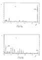
- The bit frequency signatures detected on the drilling machine of Fig 2 will now be described for a new and worn three-cone bit with reference to the power spectra shown in Fig 5a and 5b respectively.
- Fig 5a shows a typical power spectrum P obtained from the WOB fluctuations measured above a new bit drilling limestone. The spectrum is obtained from data recorded over 16 bit revolutions. When dealing with whole bit signatures, it is generally required that the spectral position of the bit related signature is independent of bit rotation speed. The power spectra have therefore been normalised to the bit rotation frequency as described previously. Peaks positioned at cone speeds and their harmonics are indicated with crosses for
cone 1, with dashed lines forcone 2 and with dots forcone 3. These spectral peaks arise from the complicated (but periodic) force fluctuations produced by the cutter wheels. The rotational speed of each cone (different from one cone to another) was measured with theproximity detectors 104. From these measurements the position of each cone frequency was determined and normalised to the bit rotation speed so as to identify them on Fig 5. They correspond topeaks cone cone 1.Peaks 122 to 130 correspond to harmonics ofpeak 118 andpeaks 132 to 142 correspond to harmonics ofpeak 120. Harmonics of cone-1 frequency are indicated bypeaks - In Fig 5b, for a bit worn at T7,
cone 1 contributes substantially to the power spectrum bypeaks 150 to 162.Cone 3 does not contribute anymore andcone 2 contributes only withpeak 164. It has been noted that, as the cones wear, their rotation speeds tend to be the same. Again, it is obvious from Fig 5, that the methods of the prior art would be very difficult to implement. Fig 5 shows that the periodic features are frequently enhanced by the wear process and this characteristic is advantageously used, in accordance with the present invention, in the algorithms described hereafter to determine cone speed without identifying tooth-row frequencies. Even for the new bit spectrum shown in Fig 5a, non-tooth-row harmonics arise from the interaction between tooth-rows, non-uniform cutter spacing and variation in cutter geometry. These effects all aid cone speed (and hence wear) determination by giving prominence to sets of harmonics, in accordance with the present invention. - When determining the cone speeds, account is taken of the fact that the range of possible bit normalised cone speeds is known for normal drilling operation (with cones with correctly functioning bearings, but in any wear state): the cone speeds are typically between 0.9 and 1.8 of the bit speed. In addition, a certain amount of result averaging is used to ensure a valid estimate of T-value, particularly as wear progresses slowly relative to the required processing time. Furthermore, as many cones as possible are identified.
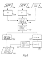
- A technique, in accordance with the present invention, for processing data which enhances the periodic nature of cone signatures to determine bit wear state is illustrated in Fig 6 under the form of a flow chart. Data are processed with the data acquisition and processing system 88 (Fig 2) or 44 (Fig 1). This system could be a general purpose computer able to perform the tasks indicated in the flow chart. Power spectra are generated using a fast Fourier transform (FFT) routine (166), from the torque (TOR) and weight-on-bit (WOB) data (168). Mud pump effects are cancelled by eliminating from the bit spectra the frequency or frequencies of the vibrations generated by the pump. For that purpose, data representing the stand pipe pressure (in
pipe 28 on Fig 1) are recorded (170) and the power spectrum is computed using a FFT (172). The WOB and TOR spectra are normalised to the bit rotation speed (174) using the rotary speed calibration (176). The spectrum P to be analysed can consist of either the individual TOR or WOB channel or the cross-spectrum which emphasizes features common to both signals (178). In order to exploit the periodic nature of the cone signatures to identify cone speeds, a two part diagnostic is preferably applied to the normalised spectrum: - . (a) The strongest peak is identified (180) within the known cone-rotation speed range (0.9 to 1.8 normalised Hz). The spectral position of this peak if taken as the repetition frequency of a dominant cone signature and is therefore a direct measure of cone-rotation speed. However, when the strongest peak cannot be identified, only following part (b) is implemented.
- . (b) To measure the dominant harmonic spacing in the power spectrum in order to extract periodicity produced by cone signatures, a "power cepstrum" analysis is applied to the data. The cepstrum is generated by computing the logarithm Y(f) of the power spectrum P (182) and by computing (184) the power spectrum of Y(f). The computation of cepstra is indicated in "Proceedings of Symposium on Time Series Analysis", Wiley, pp 209-243, 1963, by B P Bogert et al. The logarithm has the effect of desensitising the cepstrum output to the amplitudes of the various harmonics. This effect becomes additive in the cepstrum due to the additive property of the logarithm. Again the knowledge of normalised cone speed range is included (186) by selecting the position of the peak of maximum amplitude only within the inverse cone speed range. This peak position is an estimate of the dominant harmonic spacing in the spectrum and so should again be a measure of cone speed.
- Then the two cone-speed estimates are stored (188). The next vibration signals corresponding to the next data acquisition periods are then processed in the same way so as to produce successive values corresponding to a period of time during which the state of bit wear has not changed significantly. The values are averaged to produce a mean value of the cone rotation speed which is sent to the surface in the case of a MWD operation. The mean value is stored or displayed at the surface so as to monitor the variation of cone rotation speeds during the drilling process.
- The two-part diagnostic allows a means of data reduction whereby only data where the outputs agreed to within tolerable limits are accepted. In this way sections of data which do not show strong harmonic cone-rotation speed behaviour are rejected. In practice it was found that nearly all the acquired data could be used in the cone-rotation speed estimate with only minimal smoothing to reject values with high deviation from the mean values. Both parts of the diagnostic were therefore retained to give independent cone speed estimates and the possibility of obtaining more than one cone-rotation speed. This is illustrated in Fig 7a and 7b which show the cepstra C derived from the power spectra of Fig 5. The cepstra are given as a function of 1/f, the inverse of the bit-normalised frequency.
- Fig 7a (corresponding to wear state TO) shows two
distinct peaks cones dominant peak 194 corresponding to one periodicity in the spectrum of Fig 5b. This situation is likely to arise where only one cone (cone 1) gives a strongly periodic contribution during the data acquisition or where all the cone-rotation speeds are similar. - The
dominant peak 192 in Fig 7a is fromcone 2 and is not fromcone 3 which produces the strongest peak in the cone-speed range of Fig 5a ascone 1 produces the strongest harmonic generation effect. The spectrum and cepstrum results therefore obtain cone-rotation speeds from different cones in this case. - The diagnostic outputs for this data can be summarised as follows and, since the data was obtained on the laboratory drilling machine of Fig 2, can be compared with actual cone-speeds as measured using
proximity transducers 104. - Spectrum diagnostic (Fig 5a) = 1.23
Cepstrum diagnostic (Fig 7a) = 0.98
Actual cone speeds = 0.98, 1.21, 1.09. - Spectrum diagnostic (Fig 5b) = 1.58
Cepstrum diagnostic (Fig 7b) = 1.64
Actual cone speeds = 1.57, 1.43, 1.54. - For the new bit (TO) the two diagnostics detect two different cones, as shown previously. In the case of the worn bit, the two diagnostics agree to within the spectral resolution of 0.0625 normalised Hz. In both cases the diagnostic outputs agree with one or more cone speeds and the cone speed increase of around 40% between the wear extremes is readily detected.
- The cepstrum technique is by no means the only possibility for obtaining cone speed information from spectral estimates. Any other method which is sensitive to the global spectral contribution of specific cones and which measures the dominant periodicity in the spectrum can be used.
- One such technique is to not only normalise the spectrum to the bit rotation rate, but also to obtain versions of the original spectrum which are normalised to integer multiples of the bit rotation. This only requires compression of the frequency axis by integer values (1, 2, 3, etc ...) and then the compressed spectra are then multiplied together. For a continuous bit normalised power spectrum P(w), the enhanced spectrum E(w) can be stated mathematically as: E(w) = Product of P(kw), from k = 1 to k = K, where K is the number of compressed spectra multiplied together.
- Harmonics of the fundamental cone frequency coincide to reinforce the fundamental peak. This is depicted in Fig 8 for the original (K = 1) spectrum obtained from a worn bit (Fig 8a) and the harmonically enhanced spectrum E(w) (K = 4) shown in Fig 8b. Peaks which are not harmonically related do not reinforce constructively and the result is a clear improvement in the signal to noise ratio of the harmonically related component. This enhancement technique is, for example, described in Proc. Symp. Computer Processing in Communications, pp 779-798, April 1969. This technique may have computational advantages over the cepstrum, particularly if 'K', the harmonic order of interest, is small. In the flow chart of Fig 6, when this technique is used, the cepstrum determination indicated by
references - With discrete spectra, there is obviously no longer a one to one correspondence in the number of points per unit frequency between the compressed spectra (since the frequency axis has been compressed by a factor of 2, 3, ..., k, ...K). It is therefore necessary to rectify this prior to multiplication by either summing over the requisite number of points in the compressed spectra or interpolating in the less compressed versions.
- The optimum processing technique to be used in order to enhance the periodic information in the spectrum depends to a large extent on the nature of field data and the available processing power.
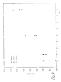
- Fig 9 shows the actual cone speeds as a function of the state of wear T of a three-cone drill bit for the 3 cones. The actual cone speeds were measured by proximity detectors in the laboratory drilling machine. This figure indicates clearly that the cone speeds increase regularly when the cone wear from TO to T8. This variation in the cone speeds provides therefore an indication of the state of wear of the bit.
- The experimental data given previously relate to WOB measurement. However, the invention applies as well to TOR measurement. The above described method makes use of Fourier transforms to obtain frequency spectra. However other methods could be used for the same purpose, for example the method known as "Maximum Entropy Spectral Estimation".
Claims (12)
Applications Claiming Priority (2)
| Application Number | Priority Date | Filing Date | Title |
|---|---|---|---|
| GB8807889 | 1988-04-05 | ||
| GB8807889A GB2217012B (en) | 1988-04-05 | 1988-04-05 | Method of determining drill bit wear |
Publications (2)
| Publication Number | Publication Date |
|---|---|
| EP0336477A1 true EP0336477A1 (en) | 1989-10-11 |
| EP0336477B1 EP0336477B1 (en) | 1991-11-27 |
Family
ID=10634556
Family Applications (1)
| Application Number | Title | Priority Date | Filing Date |
|---|---|---|---|
| EP89200745A Expired EP0336477B1 (en) | 1988-04-05 | 1989-03-23 | Method of determining drill bit wear |
Country Status (6)
| Country | Link |
|---|---|
| US (1) | US4928521A (en) |
| EP (1) | EP0336477B1 (en) |
| CA (1) | CA1298394C (en) |
| DE (1) | DE68900462D1 (en) |
| GB (1) | GB2217012B (en) |
| NO (1) | NO171741C (en) |
Cited By (16)
| Publication number | Priority date | Publication date | Assignee | Title |
|---|---|---|---|---|
| FR2666845A1 (en) * | 1990-09-14 | 1992-03-20 | Elf Aquitaine | METHOD FOR CONDUCTING A DRILL. |
| FR2673237A1 (en) * | 1991-02-25 | 1992-08-28 | Elf Aquitaine | METHOD FOR AUTOMATIC MONITORING OF THE VIBRATORY STATE OF A DRILLING TRIM. |
| WO1994024539A1 (en) * | 1993-04-21 | 1994-10-27 | Db Stratabit Limited | Apparatus for indicating wear |
| EP1195668A1 (en) * | 2000-09-27 | 2002-04-10 | LIEBHERR-VERZAHNTECHNIK GmbH | Process monitoring for detecting wear of toothed-tools |
| EP1554462A2 (en) * | 2002-06-19 | 2005-07-20 | Bj Services Company | Apparatus and method of monitoring and signaling for downhole tools |
| WO2006005337A1 (en) * | 2004-06-11 | 2006-01-19 | Nanonord A/S | A method for analyzing fundamental frequencies and application of the method |
| GB2417738A (en) * | 2000-11-07 | 2006-03-08 | Halliburton Energy Serv Inc | Determining drill bit failure by use of a neural network |
| EP2172819A2 (en) | 2008-08-27 | 2010-04-07 | China Steel Corporation | Method for evaluating grinding state |
| EP2890988A4 (en) * | 2012-08-31 | 2016-07-20 | Halliburton Energy Services Inc | System and method for detecting vibrations using an opto-analytical device |
| US9885234B2 (en) | 2012-08-31 | 2018-02-06 | Halliburton Energy Services, Inc. | System and method for measuring temperature using an opto-analytical device |
| US9945181B2 (en) | 2012-08-31 | 2018-04-17 | Halliburton Energy Services, Inc. | System and method for detecting drilling events using an opto-analytical device |
| US9957792B2 (en) | 2012-08-31 | 2018-05-01 | Halliburton Energy Services, Inc. | System and method for analyzing cuttings using an opto-analytical device |
| US10012067B2 (en) | 2012-08-31 | 2018-07-03 | Halliburton Energy Services, Inc. | System and method for determining torsion using an opto-analytical device |
| US10012070B2 (en) | 2012-08-31 | 2018-07-03 | Halliburton Energy Services, Inc. | System and method for measuring gaps using an opto-analytical device |
| US10167718B2 (en) | 2012-08-31 | 2019-01-01 | Halliburton Energy Services, Inc. | System and method for analyzing downhole drilling parameters using an opto-analytical device |
| US11365590B2 (en) | 2013-11-08 | 2022-06-21 | Halliburton Energy Services, Inc. | Dynamic wear prediction for fixed cutter drill bits |
Families Citing this family (58)
| Publication number | Priority date | Publication date | Assignee | Title |
|---|---|---|---|---|
| FR2645205B1 (en) * | 1989-03-31 | 1991-06-07 | Elf Aquitaine | DEVICE FOR AUDITIVE AND / OR VISUAL REPRESENTATION OF MECHANICAL PHENOMENAS IN A WELL AND USE OF THE DEVICE IN A METHOD OF CONDUCTING A WELL |
| GB8916459D0 (en) * | 1989-07-19 | 1989-09-06 | Forex Neptune Serv Tech Sa | Method of monitoring the drilling of a borehole |
| GB2264562B (en) * | 1992-02-22 | 1995-03-22 | Anadrill Int Sa | Determination of drill bit rate of penetration from surface measurements |
| US5864058A (en) * | 1994-09-23 | 1999-01-26 | Baroid Technology, Inc. | Detecting and reducing bit whirl |
| US6612382B2 (en) * | 1996-03-25 | 2003-09-02 | Halliburton Energy Services, Inc. | Iterative drilling simulation process for enhanced economic decision making |
| US7032689B2 (en) * | 1996-03-25 | 2006-04-25 | Halliburton Energy Services, Inc. | Method and system for predicting performance of a drilling system of a given formation |
| US5794720A (en) | 1996-03-25 | 1998-08-18 | Dresser Industries, Inc. | Method of assaying downhole occurrences and conditions |
| GB9620679D0 (en) * | 1996-10-04 | 1996-11-20 | Halliburton Co | Method and apparatus for sensing and displaying torsional vibration |
| FR2765264B1 (en) * | 1997-06-25 | 1999-08-06 | Inst Francais Du Petrole | METHOD AND SYSTEM FOR DETECTING THE PRECESSION OF AN ELEMENT OF A BORE LINING |
| FI105594B (en) | 1998-02-05 | 2000-09-15 | Tamrock Oy | An arrangement to identify the need for maintenance of a hydraulic breaker |
| JP2000081404A (en) * | 1998-06-29 | 2000-03-21 | Equos Research Co Ltd | Hydrogen quantity measuring device |
| GB2340149B (en) * | 1998-08-04 | 2002-11-20 | Camco Internat | A method of determining characteristics of a rotary drag-type drill bit |
| GB9824248D0 (en) | 1998-11-06 | 1998-12-30 | Camco Int Uk Ltd | Methods and apparatus for detecting torsional vibration in a downhole assembly |
| US6276465B1 (en) | 1999-02-24 | 2001-08-21 | Baker Hughes Incorporated | Method and apparatus for determining potential for drill bit performance |
| US6386297B1 (en) | 1999-02-24 | 2002-05-14 | Baker Hughes Incorporated | Method and apparatus for determining potential abrasivity in a wellbore |
| US6353799B1 (en) | 1999-02-24 | 2002-03-05 | Baker Hughes Incorporated | Method and apparatus for determining potential interfacial severity for a formation |
| US6601660B1 (en) * | 2000-06-08 | 2003-08-05 | Smith International, Inc. | Cutting structure for roller cone drill bits |
| US8589124B2 (en) * | 2000-08-09 | 2013-11-19 | Smith International, Inc. | Methods for modeling wear of fixed cutter bits and for designing and optimizing fixed cutter bits |
| US6631772B2 (en) | 2000-08-21 | 2003-10-14 | Halliburton Energy Services, Inc. | Roller bit rearing wear detection system and method |
| US6634441B2 (en) | 2000-08-21 | 2003-10-21 | Halliburton Energy Services, Inc. | System and method for detecting roller bit bearing wear through cessation of roller element rotation |
| US6648082B2 (en) | 2000-11-07 | 2003-11-18 | Halliburton Energy Services, Inc. | Differential sensor measurement method and apparatus to detect a drill bit failure and signal surface operator |
| US6722450B2 (en) | 2000-11-07 | 2004-04-20 | Halliburton Energy Svcs. Inc. | Adaptive filter prediction method and system for detecting drill bit failure and signaling surface operator |
| US6817425B2 (en) | 2000-11-07 | 2004-11-16 | Halliburton Energy Serv Inc | Mean strain ratio analysis method and system for detecting drill bit failure and signaling surface operator |
| US6712160B1 (en) | 2000-11-07 | 2004-03-30 | Halliburton Energy Services Inc. | Leadless sub assembly for downhole detection system |
| US6802215B1 (en) | 2003-10-15 | 2004-10-12 | Reedhyealog L.P. | Apparatus for weight on bit measurements, and methods of using same |
| GB2413403B (en) | 2004-04-19 | 2008-01-09 | Halliburton Energy Serv Inc | Field synthesis system and method for optimizing drilling operations |
| FR2882287B1 (en) * | 2005-02-24 | 2008-09-19 | Georges Renault Soc Par Action | TOOLING COMPRISING AT LEAST ONE ROTATING ORGAN AND VIBRATION FREQUENCY MEASURING MEANS OF SAID ORGAN TO DETERMINE ITS WEAR CONDITION, CONTROL UNIT AND CORRESPONDING METHOD |
| US20070106487A1 (en) * | 2005-11-08 | 2007-05-10 | David Gavia | Methods for optimizing efficiency and durability of rotary drag bits and rotary drag bits designed for optimal efficiency and durability |
| US7424910B2 (en) * | 2006-06-30 | 2008-09-16 | Baker Hughes Incorporated | Downhole abrading tools having a hydrostatic chamber and uses therefor |
| US7404457B2 (en) * | 2006-06-30 | 2008-07-29 | Baker Huges Incorporated | Downhole abrading tools having fusible material and methods of detecting tool wear |
| US7484571B2 (en) * | 2006-06-30 | 2009-02-03 | Baker Hughes Incorporated | Downhole abrading tools having excessive wear indicator |
| US7464771B2 (en) * | 2006-06-30 | 2008-12-16 | Baker Hughes Incorporated | Downhole abrading tool having taggants for indicating excessive wear |
| NO328800B1 (en) * | 2007-04-30 | 2010-05-18 | Nat Oilwell Norway As | A method for detecting a fluid leak associated with a piston machine |
| WO2009075667A2 (en) * | 2007-11-30 | 2009-06-18 | Halliburton Energy Services | Method and system for predicting performance of a drilling system having multiple cutting structures |
| WO2010039342A1 (en) * | 2008-10-03 | 2010-04-08 | Halliburton Energy Services Inc. | Method and system for predicting performance of a drilling system |
| US8006781B2 (en) * | 2008-12-04 | 2011-08-30 | Baker Hughes Incorporated | Method of monitoring wear of rock bit cutters |
| US20100139987A1 (en) * | 2008-12-10 | 2010-06-10 | Baker Hughes Incorporated | Real time dull grading |
| US9624729B2 (en) | 2008-12-10 | 2017-04-18 | Baker Hughes Incorporated | Real time bit monitoring |
| SE535585C2 (en) * | 2010-09-20 | 2012-10-02 | Spc Technology Ab | Method and apparatus for impact-acting submersible drilling |
| US9074467B2 (en) * | 2011-09-26 | 2015-07-07 | Saudi Arabian Oil Company | Methods for evaluating rock properties while drilling using drilling rig-mounted acoustic sensors |
| US10551516B2 (en) | 2011-09-26 | 2020-02-04 | Saudi Arabian Oil Company | Apparatus and methods of evaluating rock properties while drilling using acoustic sensors installed in the drilling fluid circulation system of a drilling rig |
| US9903974B2 (en) | 2011-09-26 | 2018-02-27 | Saudi Arabian Oil Company | Apparatus, computer readable medium, and program code for evaluating rock properties while drilling using downhole acoustic sensors and telemetry system |
| US9447681B2 (en) | 2011-09-26 | 2016-09-20 | Saudi Arabian Oil Company | Apparatus, program product, and methods of evaluating rock properties while drilling using downhole acoustic sensors and a downhole broadband transmitting system |
| US9234974B2 (en) | 2011-09-26 | 2016-01-12 | Saudi Arabian Oil Company | Apparatus for evaluating rock properties while drilling using drilling rig-mounted acoustic sensors |
| US9624768B2 (en) | 2011-09-26 | 2017-04-18 | Saudi Arabian Oil Company | Methods of evaluating rock properties while drilling using downhole acoustic sensors and telemetry system |
| US10180061B2 (en) | 2011-09-26 | 2019-01-15 | Saudi Arabian Oil Company | Methods of evaluating rock properties while drilling using downhole acoustic sensors and a downhole broadband transmitting system |
| US9410377B2 (en) | 2012-03-16 | 2016-08-09 | Baker Hughes Incorporated | Apparatus and methods for determining whirl of a rotating tool |
| US9169697B2 (en) | 2012-03-27 | 2015-10-27 | Baker Hughes Incorporated | Identification emitters for determining mill life of a downhole tool and methods of using same |
| US10221671B1 (en) * | 2014-07-25 | 2019-03-05 | U.S. Department Of Energy | MSE based drilling optimization using neural network simulaton |
| US10133832B2 (en) * | 2014-08-05 | 2018-11-20 | Schlumberger Technology Corporation | System and methodology for subterranean process simulation |
| US9475526B2 (en) | 2014-08-23 | 2016-10-25 | Caterpillar Inc. | Track link having a wear sensing device |
| US9868482B2 (en) | 2014-10-29 | 2018-01-16 | Caterpillar Inc. | Track roller assembly with a wear measurement system |
| US9592866B2 (en) | 2014-11-06 | 2017-03-14 | Caterpillar Inc. | Track assembly having a wear monitoring system |
| US9371630B1 (en) | 2014-12-19 | 2016-06-21 | Caterpillar Inc. | Determination of undercarriage idler and roller wear based on final drive speed |
| US10101486B1 (en) | 2017-08-10 | 2018-10-16 | Datacloud International, Inc. | Seismic-while-drilling survey systems and methods |
| SE545120C2 (en) | 2017-10-02 | 2023-04-04 | The Royal Institution For The Advancement Of Learning / Mcgill Univ | Bit condition monitoring system and method |
| US10989828B2 (en) | 2018-02-17 | 2021-04-27 | Datacloud International, Inc. | Vibration while drilling acquisition and processing system |
| US20220168862A1 (en) * | 2019-06-10 | 2022-06-02 | Halliburton Energy Services, Inc. | Cutter dull evaluation |
Citations (4)
| Publication number | Priority date | Publication date | Assignee | Title |
|---|---|---|---|---|
| US3626482A (en) * | 1968-10-30 | 1971-12-07 | Aquitaine Petrole | Method and apparatus for measuring lithological characteristics of rocks |
| GB1330191A (en) * | 1969-11-12 | 1973-09-12 | Aquitaine Petrole | Process and device for measuring wear on a drilling tool during use |
| USRE28436E (en) * | 1970-12-28 | 1975-06-03 | Method op determining downhole occurences in well drilling using rotary torque oscillation measurements | |
| GB2179736A (en) * | 1985-08-30 | 1987-03-11 | Prad Res & Dev Nv | Method of analyzing vibrations from a drilling bit in a borehole |
Family Cites Families (9)
| Publication number | Priority date | Publication date | Assignee | Title |
|---|---|---|---|---|
| US28436A (en) * | 1860-05-22 | Printer s composing-stick | ||
| US2331152A (en) * | 1941-03-17 | 1943-10-05 | Jr Floyd Willis | Means for logging wells |
| US2985829A (en) * | 1957-09-30 | 1961-05-23 | Well Surveys Inc | Method and apparatus for determining drill bit speed |
| US3345867A (en) * | 1964-09-03 | 1967-10-10 | Arps Corp | Method and apparatus for measuring rock bit wear while drilling |
| US4150568A (en) * | 1978-03-28 | 1979-04-24 | General Electric Company | Apparatus and method for down hole vibration spectrum analysis |
| US4359898A (en) * | 1980-12-09 | 1982-11-23 | Schlumberger Technology Corporation | Weight-on-bit and torque measuring apparatus |
| US4471663A (en) * | 1982-04-12 | 1984-09-18 | Exxon Production Research Co. | Drilling torquemeter |
| GB8411361D0 (en) * | 1984-05-03 | 1984-06-06 | Schlumberger Cambridge Researc | Assessment of drilling conditions |
| US4627276A (en) * | 1984-12-27 | 1986-12-09 | Schlumberger Technology Corporation | Method for measuring bit wear during drilling |
-
1988
- 1988-04-05 GB GB8807889A patent/GB2217012B/en not_active Expired - Lifetime
-
1989
- 1989-03-23 EP EP89200745A patent/EP0336477B1/en not_active Expired
- 1989-03-23 DE DE8989200745T patent/DE68900462D1/en not_active Expired - Fee Related
- 1989-03-27 US US07/328,655 patent/US4928521A/en not_active Expired - Lifetime
- 1989-03-30 CA CA000595153A patent/CA1298394C/en not_active Expired - Fee Related
- 1989-04-03 NO NO891392A patent/NO171741C/en unknown
Patent Citations (4)
| Publication number | Priority date | Publication date | Assignee | Title |
|---|---|---|---|---|
| US3626482A (en) * | 1968-10-30 | 1971-12-07 | Aquitaine Petrole | Method and apparatus for measuring lithological characteristics of rocks |
| GB1330191A (en) * | 1969-11-12 | 1973-09-12 | Aquitaine Petrole | Process and device for measuring wear on a drilling tool during use |
| USRE28436E (en) * | 1970-12-28 | 1975-06-03 | Method op determining downhole occurences in well drilling using rotary torque oscillation measurements | |
| GB2179736A (en) * | 1985-08-30 | 1987-03-11 | Prad Res & Dev Nv | Method of analyzing vibrations from a drilling bit in a borehole |
Cited By (22)
| Publication number | Priority date | Publication date | Assignee | Title |
|---|---|---|---|---|
| FR2666845A1 (en) * | 1990-09-14 | 1992-03-20 | Elf Aquitaine | METHOD FOR CONDUCTING A DRILL. |
| WO1992005337A1 (en) * | 1990-09-14 | 1992-04-02 | Societe Nationale Elf Aquitaine (Production) | Method for conducting an oil drilling operation |
| FR2673237A1 (en) * | 1991-02-25 | 1992-08-28 | Elf Aquitaine | METHOD FOR AUTOMATIC MONITORING OF THE VIBRATORY STATE OF A DRILLING TRIM. |
| WO1992014908A1 (en) * | 1991-02-25 | 1992-09-03 | Societe Nationale Elf Aquitaine (Production) | Method for automatically monitoring the vibrational condition of a drill string |
| WO1994024539A1 (en) * | 1993-04-21 | 1994-10-27 | Db Stratabit Limited | Apparatus for indicating wear |
| EP1195668A1 (en) * | 2000-09-27 | 2002-04-10 | LIEBHERR-VERZAHNTECHNIK GmbH | Process monitoring for detecting wear of toothed-tools |
| GB2417738B (en) * | 2000-11-07 | 2006-07-19 | Halliburton Energy Serv Inc | System for monitoring drill bit performance |
| GB2417738A (en) * | 2000-11-07 | 2006-03-08 | Halliburton Energy Serv Inc | Determining drill bit failure by use of a neural network |
| EP1554462A4 (en) * | 2002-06-19 | 2005-10-19 | Bj Services Co | Apparatus and method of monitoring and signaling for downhole tools |
| EP1554462A2 (en) * | 2002-06-19 | 2005-07-20 | Bj Services Company | Apparatus and method of monitoring and signaling for downhole tools |
| WO2006005337A1 (en) * | 2004-06-11 | 2006-01-19 | Nanonord A/S | A method for analyzing fundamental frequencies and application of the method |
| EP2172819A2 (en) | 2008-08-27 | 2010-04-07 | China Steel Corporation | Method for evaluating grinding state |
| EP2172819A3 (en) * | 2008-08-27 | 2012-01-11 | China Steel Corporation | Method for evaluating grinding state |
| EP2890988A4 (en) * | 2012-08-31 | 2016-07-20 | Halliburton Energy Services Inc | System and method for detecting vibrations using an opto-analytical device |
| US9885234B2 (en) | 2012-08-31 | 2018-02-06 | Halliburton Energy Services, Inc. | System and method for measuring temperature using an opto-analytical device |
| US9945181B2 (en) | 2012-08-31 | 2018-04-17 | Halliburton Energy Services, Inc. | System and method for detecting drilling events using an opto-analytical device |
| US9957792B2 (en) | 2012-08-31 | 2018-05-01 | Halliburton Energy Services, Inc. | System and method for analyzing cuttings using an opto-analytical device |
| US10006279B2 (en) | 2012-08-31 | 2018-06-26 | Halliburton Energy Services, Inc. | System and method for detecting vibrations using an opto-analytical device |
| US10012067B2 (en) | 2012-08-31 | 2018-07-03 | Halliburton Energy Services, Inc. | System and method for determining torsion using an opto-analytical device |
| US10012070B2 (en) | 2012-08-31 | 2018-07-03 | Halliburton Energy Services, Inc. | System and method for measuring gaps using an opto-analytical device |
| US10167718B2 (en) | 2012-08-31 | 2019-01-01 | Halliburton Energy Services, Inc. | System and method for analyzing downhole drilling parameters using an opto-analytical device |
| US11365590B2 (en) | 2013-11-08 | 2022-06-21 | Halliburton Energy Services, Inc. | Dynamic wear prediction for fixed cutter drill bits |
Also Published As
| Publication number | Publication date |
|---|---|
| NO171741B (en) | 1993-01-18 |
| EP0336477B1 (en) | 1991-11-27 |
| DE68900462D1 (en) | 1992-01-09 |
| NO171741C (en) | 1993-04-28 |
| GB2217012B (en) | 1992-03-25 |
| NO891392L (en) | 1989-10-06 |
| GB2217012A (en) | 1989-10-18 |
| GB8807889D0 (en) | 1988-05-05 |
| NO891392D0 (en) | 1989-04-03 |
| CA1298394C (en) | 1992-03-31 |
| US4928521A (en) | 1990-05-29 |
Similar Documents
| Publication | Publication Date | Title |
|---|---|---|
| EP0336477B1 (en) | Method of determining drill bit wear | |
| EP0409304B1 (en) | Method of monitoring the drilling of a borehole | |
| US4773263A (en) | Method of analyzing vibrations from a drilling bit in a borehole | |
| US4958125A (en) | Method and apparatus for determining characteristics of the movement of a rotating drill string including rotation speed and lateral shocks | |
| Finnie et al. | An experimental study of drill-string vibration | |
| US7680600B2 (en) | Method, system and apparatus for formation tester data processing | |
| EP3524944B1 (en) | A method for a real time frequency analysis of vibration modes in a drill string | |
| EP1693549A1 (en) | Method and apparatus for measuring stick slip while drilling | |
| EP1428976B1 (en) | System and method for processing and transmitting information from measurements made while drilling | |
| US6227044B1 (en) | Methods and apparatus for detecting torsional vibration in a bottomhole assembly | |
| US4926686A (en) | Method for determining the wear of the cutting means of a tool during drilling a rocky formation | |
| US6142228A (en) | Downhole motor speed measurement method | |
| GB2274667A (en) | Methods for analysis of drillstring vibration using torsionally induced frequency modulation | |
| US11668179B2 (en) | Drilling evaluation based on coupled torsional vibrations | |
| CN108678725A (en) | Underground frictional resistance and torque Real Time Monitoring method | |
| EP0351902B1 (en) | Method of determining the porosity of an underground formation being drilled | |
| GB2275283A (en) | Detection of bit whirl | |
| Dubinsky et al. | Surface monitoring of downhole vibrations: Russian, European, and American approaches | |
| WO2023075925A1 (en) | Design of service improvements using adaptive models derived from classified vibration mechanisms | |
| CN114607354A (en) | Method for forecasting complex drilling condition | |
| JPS6367319A (en) | Hardness index gauge | |
| RU2036301C1 (en) | Method for determination of wear of drill bit bearing and cutting structure during well drilling by screw downhole motor | |
| Jiang et al. | Development of Downhole Dynamic Measuring System and Field Trial |
Legal Events
| Date | Code | Title | Description |
|---|---|---|---|
| PUAI | Public reference made under article 153(3) epc to a published international application that has entered the european phase |
Free format text: ORIGINAL CODE: 0009012 |
|
| AK | Designated contracting states |
Kind code of ref document: A1 Designated state(s): DE FR IT NL |
|
| 17P | Request for examination filed |
Effective date: 19900404 |
|
| 17Q | First examination report despatched |
Effective date: 19910301 |
|
| RAP1 | Party data changed (applicant data changed or rights of an application transferred) |
Owner name: SERVICES PETROLIERS SCHLUMBERGER |
|
| GRAA | (expected) grant |
Free format text: ORIGINAL CODE: 0009210 |
|
| AK | Designated contracting states |
Kind code of ref document: B1 Designated state(s): DE FR IT NL |
|
| ITF | It: translation for a ep patent filed |
Owner name: BARZANO' E ZANARDO MILANO S.P.A. |
|
| REF | Corresponds to: |
Ref document number: 68900462 Country of ref document: DE Date of ref document: 19920109 |
|
| ET | Fr: translation filed | ||
| PLBE | No opposition filed within time limit |
Free format text: ORIGINAL CODE: 0009261 |
|
| STAA | Information on the status of an ep patent application or granted ep patent |
Free format text: STATUS: NO OPPOSITION FILED WITHIN TIME LIMIT |
|
| 26N | No opposition filed | ||
| PGFP | Annual fee paid to national office [announced via postgrant information from national office to epo] |
Ref country code: NL Payment date: 19930331 Year of fee payment: 5 |
|
| PGFP | Annual fee paid to national office [announced via postgrant information from national office to epo] |
Ref country code: DE Payment date: 19930518 Year of fee payment: 5 |
|
| PG25 | Lapsed in a contracting state [announced via postgrant information from national office to epo] |
Ref country code: FR Effective date: 19931130 |
|
| REG | Reference to a national code |
Ref country code: FR Ref legal event code: ST |
|
| REG | Reference to a national code |
Ref country code: FR Ref legal event code: D1 |
|
| PG25 | Lapsed in a contracting state [announced via postgrant information from national office to epo] |
Ref country code: NL Effective date: 19941001 |
|
| NLV4 | Nl: lapsed or anulled due to non-payment of the annual fee | ||
| PG25 | Lapsed in a contracting state [announced via postgrant information from national office to epo] |
Ref country code: DE Effective date: 19941201 |
|
| REG | Reference to a national code |
Ref country code: FR Ref legal event code: ST |
|
| PG25 | Lapsed in a contracting state [announced via postgrant information from national office to epo] |
Ref country code: IT Free format text: LAPSE BECAUSE OF NON-PAYMENT OF DUE FEES Effective date: 20050323 |
|
| PG25 | Lapsed in a contracting state [announced via postgrant information from national office to epo] |
Ref country code: FR Effective date: 19920331 |