EP0336367A2 - Double-side simultaneous coating equipment - Google Patents
Double-side simultaneous coating equipment Download PDFInfo
- Publication number
- EP0336367A2 EP0336367A2 EP89105881A EP89105881A EP0336367A2 EP 0336367 A2 EP0336367 A2 EP 0336367A2 EP 89105881 A EP89105881 A EP 89105881A EP 89105881 A EP89105881 A EP 89105881A EP 0336367 A2 EP0336367 A2 EP 0336367A2
- Authority
- EP
- European Patent Office
- Prior art keywords
- coater
- rolls
- base material
- coating equipment
- coating
- Prior art date
- Legal status (The legal status is an assumption and is not a legal conclusion. Google has not performed a legal analysis and makes no representation as to the accuracy of the status listed.)
- Withdrawn
Links
Images

Classifications
-
- B—PERFORMING OPERATIONS; TRANSPORTING
- B05—SPRAYING OR ATOMISING IN GENERAL; APPLYING FLUENT MATERIALS TO SURFACES, IN GENERAL
- B05C—APPARATUS FOR APPLYING FLUENT MATERIALS TO SURFACES, IN GENERAL
- B05C9/00—Apparatus or plant for applying liquid or other fluent material to surfaces by means not covered by any preceding group, or in which the means of applying the liquid or other fluent material is not important
- B05C9/04—Apparatus or plant for applying liquid or other fluent material to surfaces by means not covered by any preceding group, or in which the means of applying the liquid or other fluent material is not important for applying liquid or other fluent material to opposite sides of the work
Definitions
- the present invention is generally directed to a double-side simultaneous coating equipment, and more particularly, to a double-side simultaneous coating equipment which may be classified into a reverse roll coater suitable for simultaneously applying an aqueous dispersion especially of a fluorocarbon-based polymer on both sides of a base material formed of a plastic film or the like.
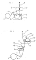
- This type of equipment is arranged such that: a base material (4) formed of a sheet of paper fed out from an unwinder (1) via a guide roll (6) to a steel roll (5) immersed in an immersion tank (2); and after both surfaces of which have been coated with a coating liquid (7), the coating liquid (7) is forced to penetrate into the base material (4) by squeezing it with scraper rolls (3) and (3′), thus obtaining a base material (8) both sides of which have been coated with the coating liquid (7).
- This type of equipment is effective in a case where the coating liquid (7) penetrates into the base material (4).
- FIG. 2 there is depicted another typical coating equipment classified as a transfer type equipment.
- the arrangement is such that: a base material (4) fed out of an unwinder (1) passes through guide roll (6); and the transfer and coating are effected at almost the same moment by coater rolls (11) and (11′) as well as by pickup rolls (10) and (10′) which scoop up adequate amounts of coating liquids (7) and (7′) within coating liquid tanks (9) and (9′) by use of cleaning doctors (12) and (12′).
- This type of coating equipment is capable of providing a well-coated material, if a transfer efficienty is high (i.e., when the base material and the coating liquid are suitably combined).
- a coating liquid for instance, a fluorine aqueous dispersion, having a low transfer efficiency depending on affinity of the base material and on the liquid nature itself, it is impossible to obtain a product with a high quality, especially good appearance.
- the present inventor has, in light of the above situation of the prior art, keenly pursued a study of the double-side simultaneous coating equipment suited to coat the fluorine aqueous dispersion on both surfaces of a plastic film.
- the present inventor has devised a reverse roll coater type of double-side simultaneous coating equipment which accomplishes the above-described object, wherein the equipment is characterized in that two coater rolls are positioned closed to each other, preferably till reaching a distance equivalent to a thickness of the base material, so that the respective coater rolls are disposed to serve as backup rolls for the other coater head.
- the present invention encompasses a coating equipment for simultaneously coating an aqueous dispersion on both sides of a base material, a reverse roll coater type of double-side simultaneous coating equipment, wherein there are provide two coater heads including at least pickup rolls and coater rolls and the two coater rolls are positioned close to each other, preferably till reaching a distance equivalent to a thickness of a base material, the respective coater rolls being so disposed to serve as backup rolls for the other coater head.
- the base material employed in this invention is not particularly limited, but a plastic film may be suitable especially for the base material.
- the plastic film may include heat-resistant plastic films such as a polyimide film, a polyamide film, a polyparabanic acid film and an aromatic polyamide film.
- the film thickness is not particularly limited, but if the film is excessively thin, a breakage will be caused therein. Inversely, in the case of its being too thick, the close-contact with the coater rolls will become unstable. For this reason, the thickness is preferable in a range of from 5 ⁇ m to 300 ⁇ m.
- the aqueous dispersion used in this invention is not particularly limited but this invention is especially suited to a fluorine-based dispersion with a low transfer efficiency.
- the fluorine dispersion is defined as an aqueous dispersion containing fluorine, more specifically, fluorocarbon polymers such as tetrafluoroethylene polymer (TFE), tetrafluoroethylene-hexafluoropropylene copolymer (FEP), tetrafluoroethylene-perfluoroalkylvinylether copolymer (PFA), tetrafluoroethylene-ethylene copolymer (ETFE) and polychlorotrifluoroethylene.
- TFE tetrafluoroethylene polymer
- FEP tetrafluoroethylene-hexafluoropropylene copolymer
- PFA tetrafluoroethylene-perfluoroalkylvinylether copolymer
- ETFE tetrafluoro
- a solid concentration of the dispersion is preferable in a range of from 10 wt% to 70 wt%.
- concentration is, however, determined depending on a thickness of final products, a viscosity of the dispersion and the like.
- the dispersion viscosity is preferably 1 cp to 100 p, more preferably 50 cp to 5 p. If the viscosity is lower than 1 cp or exceeds 100 p, the transfer efficiency decreases, and the coated surfaces are poor in appearance.
- the following agents are added to the dispersion, which include a thickener for adjusting the viscosity, a solvent such as methanol and an anti-foaming agent for eliminating the foams generated when effecting the coating process, or a pigment for coloring the dispersion.
- each of two coater heads is composed of two rolls, viz., a pickup roll (23) or (23′) and a coater roll (24) or (24′).
- FIG. 3 shows a case where a base material (25) is pulled up
- FIG. 4 illustrates a case where the base material (25) is pulled in the horizontal direction.
- the base material (25) is fed out of an unwinder (21), and subsequently coating liquids (27) and (27′) are scooped up by pickup rolls (23) and (23′) from coating liquid tanks (22) and (22′). Both sides of the base material (25) are almost simultaneously coated with the coating liquids by means of coater rolls (24) and (24′), thus obtaining a base material (28), the two sides of which have been coated with the coating liquids.
- pickup rolls (23) and (23′) are preferably formed of rubber, while coater rolls (24) and (24′) are formed of steel in terms of accuracy in thickness of the coating.
- the pickup roll of one of two coater heads is arranged to be a steel roll, while the coater roll is arranged to be a rubber roll.
- Pickup rolls (23) and (23′) do not have cleaning doctors.
- a clearance between coater rolls (24) and (24′) is set slightly wider than the thickness of the base material (25).
- the lower limit of clearance is just the base material thickness and the upper limit is set enough to exhibit a function of the respective coater rolls as backup rolls.
- the upper limit value is, though it depends on the coating thickness, approximately a 3-fold thickness of the base material.
- the clearance between two coater rolls (24) and (24′) sufficiently approximates to the thickness of the base material (25), the function of the backup rolls is sufficiently exhibited, thereby the transfer efficiency being increased. Accordingly, when attaining the same coating thickness, it is required that a ratio of the speed of the coater roll surface to that of the base material be small. In contrast, the clearance between two coater rolls (24) and (24′) is far from the thickness of the base material (25), the function as backup rolls decreases, and the transfer efficiency decreases. It is therefore necessary to increase the ratio of the speed of the coater roll surface to that of the base material.
- the coater rolls (24) and (24′) are rotated in the opposite direction to the direction in which the base material (25) advances.
- the pickup rolls (23) and (23′) may be rotated in any direction.
- the rotational direction is restricted. Namely, the coater roll (24′) is rotated in the reverse direction to the moving direction of the base material (25), whereas the pickup roll (23′) is rotated in the moving direction of the base material (25).
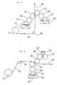
- FIGS. 5 and 6 respectively show other embodiments of the coating equipment according to the present invention.
- the coater heads individually consist of three kinds of rolls, viz., pickup rolls (23) and (23′), metering rolls (29) and (29′), and coater rolls (24) and (24′).
- FIG. 5 illustrates a case where a base material (25) is pulled up
- FIG. 6 shows a case where the base material (25) is pulled in the horizontal direction.
- the base material (25) is fed out of an unwinder (21). Subsequent to this step, coating liquids (27) and (27′) are scooped up by pickup rolls (23) and (23′), and weights thereof are measured by means of metering rolls (29) and (29′), then the two sides of base material (25) are almost simultaneously coated with the coating liquids by the coater rolls (24) and (24′), thus the base material (28), both sides of which are coated with the liquids are obtained.
- the coater rolls (24) and (24′) are preferably formed of steel, while the metering rolls (29) and (29′) are preferably formed of rubber in terms of accuracy in thickness of coating.
- the coater roll may be arranged to be a rubber roll, while the metering roll may be arranged to be a steel roll. If the metering roll is made of steel, the pickup roll is made preferably of rubber, and vice versa. As is obvious from FIGS. 5 and 6, pickup rolls (23) and (23′) are not possessed of the cleaning doctors.
- the clearance between two coater rolls (24) and (24′) has the same relation as that shown in FIGS. 3 and 4.
- a relation in speed between the base material (25) and the surfaces of coater rolls (24) and (24′) is the same as that shown in FIGS. 3 and 4.
- coater rolls (24) and (24′) are rotated in the opposite direction to the moving direction of the base material (25).
- the pickup and metering rolls (23) and (23′), (29) and (29′) may be rotated in any direction. As illustrated in FIG. 6, however, when the coating liquid (27′) is supplied from upper coating liquid tank (22′), the rotational direction is restricted.
- the pickup roll (23′) is rotated in the moving direction of the base material (25), whereas the metering roll (29′) is rotated in the reverse direction to the moving direction of the base material (25).
- the coater heads are constituted respectively by coater rolls and coating knives, (24) and (24′), (30) and (30′) for measuring an amount of coating.
- a base material (25) is fed out of an unwinder (21), and the weights of coating liquids (27) and (27′), which have been adhered to coater rolls (24) and (24′), are measured by coating knives (30) and (30′) on coater rolls (24) and (24′). Thereafter, the coating is almost simultaneously effected on both surfaces of the base material (25), and the base material (28), the two sides of which are coated with the coating liquids, is thus obtained.
- the clearance between two coater rolls (24) and (24′) has the same relation as that shown in FIGS. 3 and 4.
- the material of which coater rolls (24) and (24′) are formed may be steel or rubber. If any one of two coater rolls is made of steel, however, the other coater roll is preferably a rubber roll.
- the rotational directions of the coater rolls are conditioned by the positional relations between coating knives (30) and (30′), and coater rolls (24) and (24′).
- the rotational directions of the coater rolls are opposite to the direction in which the base material (25) is fed out.
- the speed of the coater roll surfaces may be equal to that of the base material.
- the films on the coater rolls are preferably thinned. For this reason, a ratio of the coater roll surface speed to that of the base material is set to a value of 1.1 to 20 and a preferable method is that the thin films are repeatedly transferred 1.1 to 20 times on the base material.
- a variety of coating knives are available for use.
- a preferably "cow-nose-shaped knife" depicted in FIG. 7 is adopted.
- the reverse roll coater type of double-side simultaneous coating equipment has the following features.
- the first feature is that the respective coater rolls of the two coater heads serve as backup rolls for the other coater roll.
- a spacing between the two coater rolls is equivalent to the thickness of the base material passing therethrough, in other words, the clearance therebetween is slightly larger than the thickness of the base material, thereby providing the function as backup rolls. Consequently, the efficiency of transfer from the coater rolls onto the base material remarkably increases.
- the second feature is characterized by such an arrangement that the pickup rolls are not provided with a scraper plate corresponding to a cleaning doctor.
- the use of the cleaning doctor entails striped residuals of coating liquids on the pickup rolls. This in turn causes the deterioration in appearance, because such striped residuals are directly transferred thereon.
- there is no necessity for using the scraper plate so that it is possible to obtain films having a well-finished appearance.
- the coating equipment according to the present invention can be adopted in cases where the steps (drying, cure, etc.) after the coating process has been carried out are the same, for instance, as a matter of course, when applying the coating liquids on the two surfaces of the base material, or even in the case of different coating liquids.
- a method of preparing a coating liquids is given as follows.
- the coating liquid obtained in the above-described manner was applied to both surfaces of a polyimide film (APICAL 25AH made by Kanegafuchi Chemical Industry Co., Ltd.) which was 250 mm in width and 25 ⁇ m in thickness till each thickness of FEP layers in terms of solid on the both surfaces reached 2.5 ⁇ m by use of the coating equipment depicted in FIG. 3.
- the specifications and conditions of the coating equipment are given as below: (Specifications of the double-side coating equipment)
- Coater roll steel roll having a diameter of 150 ⁇ and a face length of 300 mm
- Pickup roll silicone rubber roll (hardness: 70 degrees) having a diameter of 150 ⁇ and a face length of 300 mm
- Coater roll silicone rubber roll (hardness 70 degrees) having a diameter of 150 ⁇ and a face length of 300 mm
- Pickup roll steel roll having a diameter of 150 ⁇ and a face length of 300 mm
- Peripheral velocity of the coater roll 30 m/min at reverse rotation
- the coated film was placed in a drying furnace for 30 sec. at a temperature of 100 °C and consecutively in a cure furnace for 30 sec. at a temperature of 400°C.
- a composite film in which both surfaces of a polyimide film having a thickness of 25 ⁇ m were provided with FEP layers each having a thickness of 2.5 ⁇ m.
- the appearance of this composite film was well finished to acquire a uniform thickness (a means thickness is approximately 31 ⁇ m to 29 ⁇ m).
Abstract
There are provided two coater heads including at least pickup rolls (23,23') and coater rolls (24, 24') and the coater rolls are positioned close to each other, preferably till reaching a distance equivalent to a thickness of the base material (25), so that the coater rolls (24, 24') are disposed to serve as backup rolls for the other coater head. In accordance with the present invention, the base material can effectively be transfer-coated with an aqueous dispersion, whereby a composite material (composite film) having a well-finished appearance is obtained.
Description
- The present invention is generally directed to a double-side simultaneous coating equipment, and more particularly, to a double-side simultaneous coating equipment which may be classified into a reverse roll coater suitable for simultaneously applying an aqueous dispersion especially of a fluorocarbon-based polymer on both sides of a base material formed of a plastic film or the like.
- A variety of double-side simultaneous coating equipments for simultaneously applying the fluorine aqueous dispersion on the two sides of the base material have heretobefore been utilized. In most of cases, however, the base material used in such equipments is formed of a sheet of paper. A typical example is illustrated in, for example, FIG. 1. This type of equipment is arranged such that: a base material (4) formed of a sheet of paper fed out from an unwinder (1) via a guide roll (6) to a steel roll (5) immersed in an immersion tank (2); and after both surfaces of which have been coated with a coating liquid (7), the coating liquid (7) is forced to penetrate into the base material (4) by squeezing it with scraper rolls (3) and (3′), thus obtaining a base material (8) both sides of which have been coated with the coating liquid (7). This type of equipment is effective in a case where the coating liquid (7) penetrates into the base material (4). Whereas in the case of coating a plastic film serving as a base material with a coating liquid in a predetermined coating thickness, unlike a paper, the plastic film can not stably be held by the rolls. It is therefore quite difficult to fixedly hold a base material (4) in a given position between scraper rolls (3) and (3′) with stability.
- Referring next to FIG. 2, there is depicted another typical coating equipment classified as a transfer type equipment. The arrangement is such that: a base material (4) fed out of an unwinder (1) passes through guide roll (6); and the transfer and coating are effected at almost the same moment by coater rolls (11) and (11′) as well as by pickup rolls (10) and (10′) which scoop up adequate amounts of coating liquids (7) and (7′) within coating liquid tanks (9) and (9′) by use of cleaning doctors (12) and (12′). This type of coating equipment is capable of providing a well-coated material, if a transfer efficienty is high (i.e., when the base material and the coating liquid are suitably combined). In the case of a coating liquid, for instance, a fluorine aqueous dispersion, having a low transfer efficiency depending on affinity of the base material and on the liquid nature itself, it is impossible to obtain a product with a high quality, especially good appearance.
- It is a primary object of the present invention to provide a double-side simultaneous coating equipment capable of effectively transfer-coating an aqueous dispersion on a base material and also producing a composite material (a composite film or the like) with a well-finished appearance.
- Other objects and advantages of the invention will become apparent to those skilled in the art from the following detailed explanation.
- The present inventor has, in light of the above situation of the prior art, keenly pursued a study of the double-side simultaneous coating equipment suited to coat the fluorine aqueous dispersion on both surfaces of a plastic film. As a result, the present inventor has devised a reverse roll coater type of double-side simultaneous coating equipment which accomplishes the above-described object, wherein the equipment is characterized in that two coater rolls are positioned closed to each other, preferably till reaching a distance equivalent to a thickness of the base material, so that the respective coater rolls are disposed to serve as backup rolls for the other coater head.
-
- FIGS. 1 and 2 are schematic diagrams each illustrating a prior art coating equipment; and
- FIGS. 3 through 7 are schematic diagrams each depicting an embodiment of a double-side simultaneous coating equipment of the present invention.
- The present invention encompasses a coating equipment for simultaneously coating an aqueous dispersion on both sides of a base material, a reverse roll coater type of double-side simultaneous coating equipment, wherein there are provide two coater heads including at least pickup rolls and coater rolls and the two coater rolls are positioned close to each other, preferably till reaching a distance equivalent to a thickness of a base material, the respective coater rolls being so disposed to serve as backup rolls for the other coater head.
- The base material employed in this invention is not particularly limited, but a plastic film may be suitable especially for the base material. The plastic film may include heat-resistant plastic films such as a polyimide film, a polyamide film, a polyparabanic acid film and an aromatic polyamide film. The film thickness is not particularly limited, but if the film is excessively thin, a breakage will be caused therein. Inversely, in the case of its being too thick, the close-contact with the coater rolls will become unstable. For this reason, the thickness is preferable in a range of from 5µm to 300µm.
- The aqueous dispersion used in this invention is not particularly limited but this invention is especially suited to a fluorine-based dispersion with a low transfer efficiency. The fluorine dispersion is defined as an aqueous dispersion containing fluorine, more specifically, fluorocarbon polymers such as tetrafluoroethylene polymer (TFE), tetrafluoroethylene-hexafluoropropylene copolymer (FEP), tetrafluoroethylene-perfluoroalkylvinylether copolymer (PFA), tetrafluoroethylene-ethylene copolymer (ETFE) and polychlorotrifluoroethylene.
- A solid concentration of the dispersion is preferable in a range of from 10 wt% to 70 wt%. The concentration is, however, determined depending on a thickness of final products, a viscosity of the dispersion and the like. The dispersion viscosity is preferably 1 cp to 100 p, more preferably 50 cp to 5 p. If the viscosity is lower than 1 cp or exceeds 100 p, the transfer efficiency decreases, and the coated surfaces are poor in appearance.
- Of course, there is no problem if the following agents are added to the dispersion, which include a thickener for adjusting the viscosity, a solvent such as methanol and an anti-foaming agent for eliminating the foams generated when effecting the coating process, or a pigment for coloring the dispersion.
- Illustrative embodiments of the present invention will hereinafter be described with reference to the accompanying drawings.
- Turning to FIGS. 3 and 4, each of two coater heads is composed of two rolls, viz., a pickup roll (23) or (23′) and a coater roll (24) or (24′). FIG. 3 shows a case where a base material (25) is pulled up, while FIG. 4 illustrates a case where the base material (25) is pulled in the horizontal direction.
- Referring again to FIGS. 3 and 4, the base material (25) is fed out of an unwinder (21), and subsequently coating liquids (27) and (27′) are scooped up by pickup rolls (23) and (23′) from coating liquid tanks (22) and (22′). Both sides of the base material (25) are almost simultaneously coated with the coating liquids by means of coater rolls (24) and (24′), thus obtaining a base material (28), the two sides of which have been coated with the coating liquids. Fundamentally, pickup rolls (23) and (23′) are preferably formed of rubber, while coater rolls (24) and (24′) are formed of steel in terms of accuracy in thickness of the coating. There is no trouble if the pickup roll of one of two coater heads is arranged to be a steel roll, while the coater roll is arranged to be a rubber roll. Pickup rolls (23) and (23′) do not have cleaning doctors. A clearance between coater rolls (24) and (24′) is set slightly wider than the thickness of the base material (25). The lower limit of clearance is just the base material thickness and the upper limit is set enough to exhibit a function of the respective coater rolls as backup rolls. The upper limit value is, though it depends on the coating thickness, approximately a 3-fold thickness of the base material.
- The next description will be referred to speeds of the base material (25) and of surfaces of coater rolls (24) and (24′). In this coating method, clearances between coater rolls and pickup rolls, (24) and (23′), (24′) and (23′) are basically as narrow as possible. Thin films are formed on the respective coater rolls (24) and (24′). Then, the thin films disposed on the coater rolls (24) and (24′) are preferably transferred preferably 1.1 to 20 times on the base material (25). Hence, the surface speed of each of the coater rolls (24) and (24′) is preferably 1.1 to 20 times as high as the speed of base material (25). If the clearance between two coater rolls (24) and (24′) sufficiently approximates to the thickness of the base material (25), the function of the backup rolls is sufficiently exhibited, thereby the transfer efficiency being increased. Accordingly, when attaining the same coating thickness, it is required that a ratio of the speed of the coater roll surface to that of the base material be small. In contrast, the clearance between two coater rolls (24) and (24′) is far from the thickness of the base material (25), the function as backup rolls decreases, and the transfer efficiency decreases. It is therefore necessary to increase the ratio of the speed of the coater roll surface to that of the base material.
- Apropos of rotational directions of the individual rolls, the coater rolls (24) and (24′) are rotated in the opposite direction to the direction in which the base material (25) advances. On the other hand, the pickup rolls (23) and (23′) may be rotated in any direction. As depicted in FIG. 4, however, when the coating liquid (27′) is supplied from upper coating liquid tank (22′), the rotational direction is restricted. Namely, the coater roll (24′) is rotated in the reverse direction to the moving direction of the base material (25), whereas the pickup roll (23′) is rotated in the moving direction of the base material (25).
- FIGS. 5 and 6 respectively show other embodiments of the coating equipment according to the present invention. The coater heads individually consist of three kinds of rolls, viz., pickup rolls (23) and (23′), metering rolls (29) and (29′), and coater rolls (24) and (24′). FIG. 5 illustrates a case where a base material (25) is pulled up, while FIG. 6 shows a case where the base material (25) is pulled in the horizontal direction.
- Referring to FIGS. 5 and 6, the base material (25) is fed out of an unwinder (21). Subsequent to this step, coating liquids (27) and (27′) are scooped up by pickup rolls (23) and (23′), and weights thereof are measured by means of metering rolls (29) and (29′), then the two sides of base material (25) are almost simultaneously coated with the coating liquids by the coater rolls (24) and (24′), thus the base material (28), both sides of which are coated with the liquids are obtained. The coater rolls (24) and (24′) are preferably formed of steel, while the metering rolls (29) and (29′) are preferably formed of rubber in terms of accuracy in thickness of coating. In one of two coater heads, the coater roll may be arranged to be a rubber roll, while the metering roll may be arranged to be a steel roll. If the metering roll is made of steel, the pickup roll is made preferably of rubber, and vice versa. As is obvious from FIGS. 5 and 6, pickup rolls (23) and (23′) are not possessed of the cleaning doctors.
- The clearance between two coater rolls (24) and (24′) has the same relation as that shown in FIGS. 3 and 4. A relation in speed between the base material (25) and the surfaces of coater rolls (24) and (24′) is the same as that shown in FIGS. 3 and 4. With respect to the rotational directions of the individual rolls, coater rolls (24) and (24′) are rotated in the opposite direction to the moving direction of the base material (25). On the other hand, the pickup and metering rolls (23) and (23′), (29) and (29′) may be rotated in any direction. As illustrated in FIG. 6, however, when the coating liquid (27′) is supplied from upper coating liquid tank (22′), the rotational direction is restricted. The pickup roll (23′) is rotated in the moving direction of the base material (25), whereas the metering roll (29′) is rotated in the reverse direction to the moving direction of the base material (25).
- Turning attention to FIG. 7, there is illustrated still another embodiment of the present invention. The coater heads are constituted respectively by coater rolls and coating knives, (24) and (24′), (30) and (30′) for measuring an amount of coating. In FIG. 7, a base material (25) is fed out of an unwinder (21), and the weights of coating liquids (27) and (27′), which have been adhered to coater rolls (24) and (24′), are measured by coating knives (30) and (30′) on coater rolls (24) and (24′). Thereafter, the coating is almost simultaneously effected on both surfaces of the base material (25), and the base material (28), the two sides of which are coated with the coating liquids, is thus obtained.
- The clearance between two coater rolls (24) and (24′) has the same relation as that shown in FIGS. 3 and 4. The material of which coater rolls (24) and (24′) are formed may be steel or rubber. If any one of two coater rolls is made of steel, however, the other coater roll is preferably a rubber roll. The rotational directions of the coater rolls are conditioned by the positional relations between coating knives (30) and (30′), and coater rolls (24) and (24′). The rotational directions of the coater rolls are opposite to the direction in which the base material (25) is fed out. The speed of the coater roll surfaces may be equal to that of the base material. For the purpose of providing a well-finished appearance, the films on the coater rolls are preferably thinned. For this reason, a ratio of the coater roll surface speed to that of the base material is set to a value of 1.1 to 20 and a preferable method is that the thin films are repeatedly transferred 1.1 to 20 times on the base material.
- A variety of coating knives are available for use. For attaining the well-finished appearance, however, a preferably "cow-nose-shaped knife" depicted in FIG. 7 is adopted.
- The reverse roll coater type of double-side simultaneous coating equipment has the following features.
- The first feature is that the respective coater rolls of the two coater heads serve as backup rolls for the other coater roll. Hence, a spacing between the two coater rolls is equivalent to the thickness of the base material passing therethrough, in other words, the clearance therebetween is slightly larger than the thickness of the base material, thereby providing the function as backup rolls. Consequently, the efficiency of transfer from the coater rolls onto the base material remarkably increases.
- The second feature is characterized by such an arrangement that the pickup rolls are not provided with a scraper plate corresponding to a cleaning doctor. The use of the cleaning doctor entails striped residuals of coating liquids on the pickup rolls. This in turn causes the deterioration in appearance, because such striped residuals are directly transferred thereon. In accordance with the present invention, there is no necessity for using the scraper plate, so that it is possible to obtain films having a well-finished appearance.
- Thus, even on the occasion of employing an aqueous dispersion with a low transfer efficiency or a plastic film which is difficult to stably hold as the base material between the rolls, the transfer-coating is effectively performed on the base material, and further the well-finished appearance can be obtained.
- The coating equipment according to the present invention can be adopted in cases where the steps (drying, cure, etc.) after the coating process has been carried out are the same, for instance, as a matter of course, when applying the coating liquids on the two surfaces of the base material, or even in the case of different coating liquids.
- The present invention will be explained in more detail by way of examples but it is not limited thereto or thereby.
- A method of preparing a coating liquids is given as follows.
- 10.2 kg of pure water and 60 g of CARBOPOLE 934 (a thickener made by Goodrich Corp.) were stirred for 15 minutes by means of a mixer. Subsequently, 112 g of an aqueous ammonia solution (25 to 28 wt%) was added to the mixture. Then, 19.8 kg of NEOFLON ND-1 (an FEP aqueous dispersion made by Daikin Industries Ltd.) and 6 g of KM-85 (anti-foaming agent made by Shin-Etsu Chemical Co., Ltd.) were further added and the mixture was stirred for 15 minutes. The thus obtained coating liquid had a solid concentration of 33 wt% and a viscosity of 100 cp.
- The coating liquid obtained in the above-described manner was applied to both surfaces of a polyimide film (APICAL 25AH made by Kanegafuchi Chemical Industry Co., Ltd.) which was 250 mm in width and 25 µm in thickness till each thickness of FEP layers in terms of solid on the both surfaces reached 2.5 µm by use of the coating equipment depicted in FIG. 3. The specifications and conditions of the coating equipment are given as below:
(Specifications of the double-side coating equipment) - Coater roll: steel roll having a diameter of 150 ⌀ and a face length of 300 mm
- Pickup roll: silicone rubber roll (hardness: 70 degrees) having a diameter of 150⌀ and a face length of 300 mm
- Coater roll: silicone rubber roll (hardness 70 degrees) having a diameter of 150⌀ and a face length of 300 mm
- Pickup roll: steel roll having a diameter of 150 ⌀ and a face length of 300 mm
- Clearance between the two coater rolls: 27 µm
- Line speed: 10 m/min
- Peripheral velocity of the coater roll: 30 m/min at reverse rotation
- Peripheral velocity of the pickup roll: 10 m/min at reverse rotation
- Clearance between the coater roll and the pickup roll: 10 µm
- After being coated under such conditions, the coated film was placed in a drying furnace for 30 sec. at a temperature of 100 °C and consecutively in a cure furnace for 30 sec. at a temperature of 400°C. As a result of these processes, there was obtained a composite film in which both surfaces of a polyimide film having a thickness of 25 µm were provided with FEP layers each having a thickness of 2.5µm. The appearance of this composite film was well finished to acquire a uniform thickness (a means thickness is approximately 31 µm to 29 µm).
- Although the illustrative embodiments of the present invention have been described in greater detail with reference to the accompanying drawings, various changes or modifications may be effected therein by one skilled in the art without departing from the scope or spirit of the invention.
Claims (8)
1. A coating equipment of a reverse roll coater type for simultaneously coating an aqueous dispersion on both sides of a base material, wherein there are provided two coater heads including at least pickup rolls and coater rolls and the two coater rolls are positioned close to each other and also disposed to serve as backup rolls for said other coater head.
2. The coating equipment as set forth in Claim 1, wherein the coater rolls are positioned close to a thickness of the base material.
3. The coating equipment as set forth in Claim 1 or 2, wherein a surface speed of each of the coater rolls is 1.1 to 20 times as high as a speed of the base material.
4. The coating equipment as set forth in any one of Claims 1 to 3, wherein the aqueous dispersion comprises a fluorine-based aqueous dispersion.
5. The coating equipment as set forth in Claim 4, wherein the fluorine-based aqueous dispersion comprises at least one selected from the group consisting of tetrafluoroethylene polymer, tetrafluoroethylene-hexafluoropropylene copolymer, tetrafluoroethylene-perfluoroalkylvinylether copolymer, tetrafluoroethylene-ethylene copolymer and polychlorotrifluoroethylene.
6. The coating equipment as set forth in any one of Claims 1 to 5,
wherein the base material comprises a plastic film.
wherein the base material comprises a plastic film.
7. The coating equipment as set forth in Claim 6, wherein the plastic film comprises a heat-resistant plastic film.
8. The coating equipment as set forth in Claim 7, wherein the heat-resistant plastic film is selected from the group consisting of polyimide film, polyamide film, polyparabanic acid film and aromatic polyamide film.
Applications Claiming Priority (2)
| Application Number | Priority Date | Filing Date | Title |
|---|---|---|---|
| JP84843/88 | 1988-04-05 | ||
| JP63084843A JP2700322B2 (en) | 1988-04-05 | 1988-04-05 | Double-sided simultaneous coating device |
Publications (2)
| Publication Number | Publication Date |
|---|---|
| EP0336367A2 true EP0336367A2 (en) | 1989-10-11 |
| EP0336367A3 EP0336367A3 (en) | 1990-08-08 |
Family
ID=13842079
Family Applications (1)
| Application Number | Title | Priority Date | Filing Date |
|---|---|---|---|
| EP89105881A Withdrawn EP0336367A3 (en) | 1988-04-05 | 1989-04-04 | Double-side simultaneous coating equipment |
Country Status (2)
| Country | Link |
|---|---|
| EP (1) | EP0336367A3 (en) |
| JP (1) | JP2700322B2 (en) |
Cited By (2)
| Publication number | Priority date | Publication date | Assignee | Title |
|---|---|---|---|---|
| EP0480897A1 (en) * | 1990-10-12 | 1992-04-15 | Valmet Corporation | Device for metering of a coating agent onto a moving base |
| CN113769990A (en) * | 2021-08-20 | 2021-12-10 | 山东亿隆薄膜材料有限责任公司 | Two-sided vertical coating mechanism of film |
Families Citing this family (2)
| Publication number | Priority date | Publication date | Assignee | Title |
|---|---|---|---|---|
| JP2002361152A (en) * | 2001-06-04 | 2002-12-17 | Tdk Corp | Double-side coater and manufacturing method of electrode for battery |
| KR102351006B1 (en) * | 2021-08-26 | 2022-01-12 | 노일호 | Coating machine |
Citations (2)
| Publication number | Priority date | Publication date | Assignee | Title |
|---|---|---|---|---|
| GB2014481A (en) * | 1978-02-14 | 1979-08-30 | Appleton Paper Inc | Coating apparatus and method |
| WO1980000928A1 (en) * | 1978-11-13 | 1980-05-15 | H Wallsten | Method and apparatus for the double-sided coating of a moving web of material,preferably a paper web |
Family Cites Families (1)
| Publication number | Priority date | Publication date | Assignee | Title |
|---|---|---|---|---|
| JPS6316868U (en) * | 1986-07-17 | 1988-02-04 |
-
1988
- 1988-04-05 JP JP63084843A patent/JP2700322B2/en not_active Expired - Lifetime
-
1989
- 1989-04-04 EP EP89105881A patent/EP0336367A3/en not_active Withdrawn
Patent Citations (2)
| Publication number | Priority date | Publication date | Assignee | Title |
|---|---|---|---|---|
| GB2014481A (en) * | 1978-02-14 | 1979-08-30 | Appleton Paper Inc | Coating apparatus and method |
| WO1980000928A1 (en) * | 1978-11-13 | 1980-05-15 | H Wallsten | Method and apparatus for the double-sided coating of a moving web of material,preferably a paper web |
Cited By (2)
| Publication number | Priority date | Publication date | Assignee | Title |
|---|---|---|---|---|
| EP0480897A1 (en) * | 1990-10-12 | 1992-04-15 | Valmet Corporation | Device for metering of a coating agent onto a moving base |
| CN113769990A (en) * | 2021-08-20 | 2021-12-10 | 山东亿隆薄膜材料有限责任公司 | Two-sided vertical coating mechanism of film |
Also Published As
| Publication number | Publication date |
|---|---|
| JPH01258761A (en) | 1989-10-16 |
| JP2700322B2 (en) | 1998-01-21 |
| EP0336367A3 (en) | 1990-08-08 |
Similar Documents
| Publication | Publication Date | Title |
|---|---|---|
| US4518637A (en) | Coating solution metering method and apparatus | |
| CA1116480A (en) | Process and apparatus for coating a web | |
| EP0706833A1 (en) | Continuous painting method | |
| GB2070459A (en) | Method of simultaneously applying multiple layers of coating liquids to a web | |
| KR100509125B1 (en) | Method for Minimizing Waste When Coating a Fluid with a Slide Coater | |
| EP0336367A2 (en) | Double-side simultaneous coating equipment | |
| CA1131078A (en) | Dry transfer system | |
| US4147126A (en) | Coating apparatus | |
| US4302486A (en) | Method of solvent coating with gravure roll in combination with sheathed elastomeric roll and apparatus | |
| JP2889128B2 (en) | Coating method and device | |
| GB1571946A (en) | Process and device for coating a film | |
| US3756195A (en) | Apparatus for coating a continuous web | |
| EP0344089B1 (en) | Process for forming a fuel cell matrix | |
| US6444270B1 (en) | Photo film coating method for coating web-shaped base material | |
| JPH06170312A (en) | Application method with bar and apparatus | |
| JP4506450B2 (en) | Roll coating method and apparatus | |
| JPH0440254A (en) | Apparatus for manufacturing re-release sheet | |
| JPS5857231B2 (en) | Tofuhouhou | |
| JP2001000900A (en) | Coating method and device | |
| JP2000343012A (en) | Rod for coating device | |
| JPH034966A (en) | Coating method | |
| JPS605256A (en) | Cylinder coating apparatus | |
| JPH04244264A (en) | Coating method | |
| GB1600616A (en) | Coating sheet material with liquids | |
| JPH09276781A (en) | Coating method |
Legal Events
| Date | Code | Title | Description |
|---|---|---|---|
| PUAI | Public reference made under article 153(3) epc to a published international application that has entered the european phase |
Free format text: ORIGINAL CODE: 0009012 |
|
| AK | Designated contracting states |
Kind code of ref document: A2 Designated state(s): BE DE FR GB IT |
|
| PUAL | Search report despatched |
Free format text: ORIGINAL CODE: 0009013 |
|
| AK | Designated contracting states |
Kind code of ref document: A3 Designated state(s): BE DE FR GB IT |
|
| STAA | Information on the status of an ep patent application or granted ep patent |
Free format text: STATUS: THE APPLICATION IS DEEMED TO BE WITHDRAWN |
|
| 18D | Application deemed to be withdrawn |
Effective date: 19910211 |