EP0336328A2 - Apparatus for optically recording and reproducing information - Google Patents
Apparatus for optically recording and reproducing information Download PDFInfo
- Publication number
- EP0336328A2 EP0336328A2 EP89105784A EP89105784A EP0336328A2 EP 0336328 A2 EP0336328 A2 EP 0336328A2 EP 89105784 A EP89105784 A EP 89105784A EP 89105784 A EP89105784 A EP 89105784A EP 0336328 A2 EP0336328 A2 EP 0336328A2
- Authority
- EP
- European Patent Office
- Prior art keywords
- information
- order diffraction
- recording
- diffraction light
- optical
- Prior art date
- Legal status (The legal status is an assumption and is not a legal conclusion. Google has not performed a legal analysis and makes no representation as to the accuracy of the status listed.)
- Granted
Links
Images

Classifications
-
- G—PHYSICS
- G11—INFORMATION STORAGE
- G11B—INFORMATION STORAGE BASED ON RELATIVE MOVEMENT BETWEEN RECORD CARRIER AND TRANSDUCER
- G11B7/00—Recording or reproducing by optical means, e.g. recording using a thermal beam of optical radiation by modifying optical properties or the physical structure, reproducing using an optical beam at lower power by sensing optical properties; Record carriers therefor
- G11B7/12—Heads, e.g. forming of the optical beam spot or modulation of the optical beam
- G11B7/14—Heads, e.g. forming of the optical beam spot or modulation of the optical beam specially adapted to record on, or to reproduce from, more than one track simultaneously
-
- G—PHYSICS
- G11—INFORMATION STORAGE
- G11B—INFORMATION STORAGE BASED ON RELATIVE MOVEMENT BETWEEN RECORD CARRIER AND TRANSDUCER
- G11B7/00—Recording or reproducing by optical means, e.g. recording using a thermal beam of optical radiation by modifying optical properties or the physical structure, reproducing using an optical beam at lower power by sensing optical properties; Record carriers therefor
- G11B7/002—Recording, reproducing or erasing systems characterised by the shape or form of the carrier
- G11B7/0033—Recording, reproducing or erasing systems characterised by the shape or form of the carrier with cards or other card-like flat carriers, e.g. flat sheets of optical film
-
- G—PHYSICS
- G11—INFORMATION STORAGE
- G11B—INFORMATION STORAGE BASED ON RELATIVE MOVEMENT BETWEEN RECORD CARRIER AND TRANSDUCER
- G11B7/00—Recording or reproducing by optical means, e.g. recording using a thermal beam of optical radiation by modifying optical properties or the physical structure, reproducing using an optical beam at lower power by sensing optical properties; Record carriers therefor
- G11B7/08—Disposition or mounting of heads or light sources relatively to record carriers
- G11B7/09—Disposition or mounting of heads or light sources relatively to record carriers with provision for moving the light beam or focus plane for the purpose of maintaining alignment of the light beam relative to the record carrier during transducing operation, e.g. to compensate for surface irregularities of the latter or for track following
- G11B7/0938—Disposition or mounting of heads or light sources relatively to record carriers with provision for moving the light beam or focus plane for the purpose of maintaining alignment of the light beam relative to the record carrier during transducing operation, e.g. to compensate for surface irregularities of the latter or for track following servo format, e.g. guide tracks, pilot signals
-
- G—PHYSICS
- G11—INFORMATION STORAGE
- G11B—INFORMATION STORAGE BASED ON RELATIVE MOVEMENT BETWEEN RECORD CARRIER AND TRANSDUCER
- G11B7/00—Recording or reproducing by optical means, e.g. recording using a thermal beam of optical radiation by modifying optical properties or the physical structure, reproducing using an optical beam at lower power by sensing optical properties; Record carriers therefor
- G11B7/12—Heads, e.g. forming of the optical beam spot or modulation of the optical beam
- G11B7/13—Optical detectors therefor
-
- G—PHYSICS
- G11—INFORMATION STORAGE
- G11B—INFORMATION STORAGE BASED ON RELATIVE MOVEMENT BETWEEN RECORD CARRIER AND TRANSDUCER
- G11B7/00—Recording or reproducing by optical means, e.g. recording using a thermal beam of optical radiation by modifying optical properties or the physical structure, reproducing using an optical beam at lower power by sensing optical properties; Record carriers therefor
- G11B7/12—Heads, e.g. forming of the optical beam spot or modulation of the optical beam
- G11B7/135—Means for guiding the beam from the source to the record carrier or from the record carrier to the detector
-
- G—PHYSICS
- G11—INFORMATION STORAGE
- G11B—INFORMATION STORAGE BASED ON RELATIVE MOVEMENT BETWEEN RECORD CARRIER AND TRANSDUCER
- G11B7/00—Recording or reproducing by optical means, e.g. recording using a thermal beam of optical radiation by modifying optical properties or the physical structure, reproducing using an optical beam at lower power by sensing optical properties; Record carriers therefor
- G11B7/08—Disposition or mounting of heads or light sources relatively to record carriers
- G11B7/09—Disposition or mounting of heads or light sources relatively to record carriers with provision for moving the light beam or focus plane for the purpose of maintaining alignment of the light beam relative to the record carrier during transducing operation, e.g. to compensate for surface irregularities of the latter or for track following
- G11B7/0901—Disposition or mounting of heads or light sources relatively to record carriers with provision for moving the light beam or focus plane for the purpose of maintaining alignment of the light beam relative to the record carrier during transducing operation, e.g. to compensate for surface irregularities of the latter or for track following for track following only
- G11B7/0903—Multi-beam tracking systems
Definitions
- the present invention relates to an apparatus for optically recording and reproducing information, and more particularly to an apparatus as above for use with a card type optical information recording medium.
- an optical information recording medium of this type there is known a so-called write-once type optical card capable of recording information once and reproducing the recorded information plural times.
- a write-once type optical card hereinafter simply called an optical card
- the fine light spot (hereinafter simply called a light spot) is applied onto an information recording area of the optical card while scanning it along the information recording area.
- the information is accordingly recorded in the optical card as a pit train (information track) optically detectable, e.g., based on a difference of light reflectance between the pit area and the other area.
- a light spot having less optical energy than that used for the recording is applied onto the information track while scanning it along the track. The reflected light from the information track is detected to reproduce the recorded information.
- An optical head is generally used for recording/reproducing information while applying a light spot onto an optical card.
- Either an optical head or an optical card is reciprocally moved in order to conduct light beam scanning.
- an optical head is a precision instrument constructed of a number of optical components and drive elements so that it has a poor resistance against impact motions such as rapid acceleration and deceleration.
- An optical card should be maintained so as to have no warp and held in position on a shuttle with as small a setting error as possible. Therefore, the shuttle is sufficiently strongly constructed to press an optical card and adjust warp or the like to some degree, resulting in a limit to making it light-weight.
- the first speed may be the same as that conventionally used.
- the term "reproducing information” is intended to mean picking up information from the information track by using a light spot
- the term “reading information” is intended to mean picking up the reproduced information from the memory into which the reproduced image has been stored.
- the above object can be achieved by the apparatus for optically recording and reproducing information of this invention.
- the apparatus uses an optical head having a diffraction grating and an optical information recording medium having guide tracks.
- Information recording is carried out using a zero-order diffraction light beam from the diffraction grating, whereas tracking is carried out using plus/minus first-order diffraction light beams from the diffraction grating.
- tracking is carried out using a zero-order light beam from the diffraction grating, whereas information reproducing is carried out using higher-order diffraction light beams including at least plus/minus first-order diffraction light beams. Focussing is carried out using a zero-order light beam both for the information recording and reproduction.
- a semiconductor laser of the optical head is activated at high optical output power for the information recording, and at low optical output power for the information reproduction.
- a plurality of information signals obtained from the reproduced information by using the higher order diffraction light beams containing at least plus/minus first order diffraction light beams are temporarily stored in a plurality of memories. Thereafter, the information signals stored in the memories are sequentially read at a speed faster than that of storing the information signals.
- the zero-order diffraction light beam obtained from a diffraction grating is applied onto the recording medium.
- the zero-order diffraction light beam has the highest energy among diffraction light beams from a diffraction grating. Tracking is carried out using plus/minus first-order diffraction light beams having lower energy than the zero-order diffraction light beam, whereas focussing is carried out using the zero-order diffraction light beams reflected from the surface of the recording medium.
- the three-beam method using zero-order and plus/minus first-order diffraction light beams from a diffraction grating is employed in recording information while carrying out tracking.
- tracking is carried out using the zero-order diffraction light beam from the diffraction grating in a push-pull manner, whereas the information is reproduced using plus/minus first- or higher- order diffraction light beams. Therefore, after recording information by using a highly stable tracking method, the information can be read at high speed, without changing the scan speed of a light spot applied to and scanned on an optical information recording medium, by providing a simple switching circuitry. Therefore, the performance of information read can be improved and a compact and cost effective apparatus can be realized.
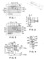
- Fig. 1 shows a positional relationship between an optical card and light spots while information is recorded in the card by using the apparatus of this invention.
- an optical card 1 is formed with guide tracks 2 (2a, 2b, 2c, ...) having, e.g., a smaller light reflectance, and information recording areas 3 (3a, 3b, 3c, ...) interposed between guide tracks 2.
- an optical head applies three light spots onto the optical card 1. Namely, a light spot 4 is applied onto the information area 3a, a light spot 5a onto both the information area 3a and guide track 2a, and a light spot 5b onto both the information area 3a and guide track 2b.
- the light spot 4 uses the zero-order diffraction light beam from a diffraction grating for performing information recording and focussing.
- Information pits 6 are formed using the zero-order diffraction beam having the highest light energy among respective order diffraction light beams.
- Automatic focussing control is conducted by the well known astigmatism method using light reflected from the optical card.
- the light spots 5a and 5b use the plus/minus first order diffraction light beams from the diffraction grating.
- the light spots 5a and 5b having the light energy smaller than the light spot 4 scan parts of the guide tracks 2a and 2b, respectively, to thus conduct tracking control in such a manner that the light spot 4 correctly scans the center of the information recording area 3a.
- Fig. 2 shows an example of the structure of an optical head for applying a plurality of light spots onto an optical card 1 to record and reproduce information.
- a divergent laser beam radiated from a semiconductor laser 7 is made parallel by a collimator lens 8 and thereafter, applied to a diffraction grating 9 to generate a plurality of diffraction light beams including those of the zero order, plus/minus first order, and higher order diffraction light beams.
- These plural diffraction light beams pass through a beam splitter 10 and are applied to a focussing lens 11 to produce light spots 4, 5a and 5b which are applied onto the optical card 1.
- the focussing lens 11 is adapted to move in two directions, one being the direction perpendicular to the surface of the optical card 1, and the other being the direction orthogonal to the guide track 2.
- a plurality of laser beams applied to the optical card 1 are reflected therefrom in accordance with the reflectance of the surface of the optical card 1, reversely applied to the focussing lens 11, reflected by the beam splitter 10 to be directed to the right side, focussed by a light receiving lens 12, imparted with astigmatism by a cylindrical lens 13, and applied to a photodiode 14 which converts optical information contained in the laser beam reflected from the optical card, into electric information.
- Fig. 3 is a schematic plan view showing an optical card and light spots on the card while information is read at a speed twice as fast as the reproducing speed by using the apparatus of this invention.
- an optical card 1 is formed with guide tracks 2 (2a, 2b, 2c, ...) and information tracks 15 (15a, 15b, 15c, ...) composed of information pits 6.
- An optical head applies a light spot 4 onto the guide track 2b, a light spot 5a onto the information track 15a, and a light spot 5b onto the information track 15b.
- the light spot 4 is used for picking up focussing and tracking control signals, the former being by means of the astigmatism method or the like and the latter by means of the push-pull method or the like, respectively of well known in the art.
- the light spots 5a and 5b are used for picking up information signals. For instance, the optical card 1 is moved from the right to the left in the direction indicated by an arrow S to thus relatively scan the light spots 5a and 5b and reproduce the information signals on the information tracks 15a and 15b, respectively.
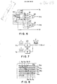
- Fig. 4 shows an example of the arrangement of photodiodes 14, and three light spots received thereon.
- Photodiode elements 14A, 14B, 14C and 14D are disposed at the central area in the form of 2 x 2 matrix, and photodiode elements 14E and 14F are disposed at the upper and lower sides.
- Three laser beams reflected from the optical card 1 pass through the light receiving lens 12 and cylindrical lens 13 and focussed on the photodiodes 14 as light spots 16, 17a and 17b.
- the signals VFO and VTR are used as the focussing and tracking control signals, as is well known in the art.
- the signals VFO and VTR are used as the focussing and tracking control signals, as is well known in the art.
- the electric outputs VE and VF from the photodiode elements 14E and 14F are the reproduced signals from the information tracks 15a and 15b which are read at a higher speed than the reproducing speed as in the following. Namely, as shown in Fig. 7, the reproduced signals VE and VF (during a period T) are temporarily stored in memories 24 and 25, respectively. Thereafter, the reproduced and stored information signal VE in the memory 24 is first read at a clock speed twice as fast as the clocks contained in the reproduced information signal VE, and then the reproduced and stored information signal VF in the memory 25 is read at a clock speed twice as fast as the clocks contained in the reproduced information signal VF. Therefore, the information signal V(E+F) is obtained (during the period T). As described above, the information reading speed is twice as fast as the information reproducing speed per one information track.
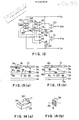
- Fig. 8 is a schematic plan view showing an optical card and light spots on the card while information is read at a speed four times faster than the reproducing speed by using the apparatus of this invention.
- the diffraction grating 9 of the optical head shown in Fig. 2 produces five diffraction light beams including zeroth order, plus/minus first order, and plus/minus third order diffraction light beams. These five light beams are focussed onto the surface of the optical card 1 as light spots 4, 5a, 5b, 5c and 5d by means of the focussing lens 11 which is adapted to be movable in the direction perpendicular to the surface of the optical card 1 and in the direction orthogonal to the guide track 2.
- light spots 5m and 5n of the plus/minus second order diffraction light beams are also produced. However, these light spots are not relevant to this invention, and so their description is omitted.
- the light spot 4 applied to the guide track 2b of the optical card 1 is reflected therefrom with the focussing information and tracking information being supplied.
- the light spots 5a, 5b, 5c and 5d applied to the information tracks 15a, 15b, 15c and 15d are reflected therefrom with the information recorded on the tracks being supplied.
- the five laser beams reflected from the optical card 1 are applied to the photodiodes 14 and converted into electric information signals corresponding to the optical information contained in the laser beams.
- Fig. 9 shows an example of the arrangement of photodiodes 14, and five spots received on the photodiodes, to be used in the embodiment shown in Fig. 8.
- the arrangement of photodiodes 14 has additional photodiode elements 14G and 14H at the upper and lower sides, as compared with the photodiodes 14 shown in Fig. 4.
- the five laser beams reflected from the optical card 1 are focussed onto the surface of the photodiodes 14 as light spots 16, 17a, 17b, 17c and 17d as shown in Fig. 9.
- the focussing and tracking control signals VFO and VTR shown in Fig. 10 similar to those shown in Fig. 5 are picked up from the photodiodes 14.
- the reproduced information signals VE, VF, VG and VH are picked up from the photodiode elements 14E, 14F, 14G and 14H, respectively.
- the electric information signals VE, VF, VG and VH are the reproduced information signals from the information tracks 15a, 15b, 15d and 15c, respectively, which are read at a higher speed than the reproducing speed as in the following. Namely, as shown in Fig. 11, the reproduced signals VE, VF, VG and VH (during a period T) are temporarily stored in memories 24, 25, 26 and 27, respectively.
- the reproduced and stored information signals VG, VE, VF and VH are read sequentially in this order from the memories 26, 24, 25 and 27 at a clock speed four times as fast as the clocks contained in the reproduced information signals VG, VE, VF and VH, respectively. Therefore, the information signal V(G+E+F+H) is obtained (during the period T). As described above, the information reading speed is four times as fast as the information reproduction speed per information track.
- higher- and odd-order diffraction light beams including plus/minus fifth-order, seventh-order diffraction light beams and so on, from the diffraction grating may be used to obtain still higher read speeds.
- light spots 5 applied to the optical card 1 are obliquely aligned relative to the guide track 2 and information track 15 as shown in Figs. 1, 3 and 8.
- light spots 5 may be aligned perpendicular to the guide track 2 and information track 15 on the condition that adjacent light spots are not superposed in part one upon another.
- higher- and even-order diffraction light beams including plus/minus second-order, fourth-order diffraction light beams from the diffraction grating are not needed, so that it is desirable to design the diffraction grating 9 such that the diffraction light beams of even order have as small an intensity as possible.
- light spots 5 are applied to the optical card 1 while sequentially and reciprocally scanning the spots 5.
- Information is stored in a memory at the forward scan, whereas for backward scan, the stored information is read at a speed two times, four or more times faster than the reproducing speed and at the same time, information on the new information tracks is stored in the memory.
- a single light spot is generally used while reciprocally scanning it. Therefore, use of a plurality of light spots in reproducing information as in the case of the present invention results in reversed time sequence for adjacent information tracks. Whether the reproduced information is at the forward or backward scan can be easily detected on the basis of the address signal recorded on the end portion of each information track. Therefore, the reversed time sequence can be corrected at the time the information is read from the memory.
- the same optical head is used for both information recording and information reproduction following high speed information read. Therefore, it is necessary to switch the electric circuits and optical systems between both cases.
- a large current near the rated value is supplied to the semiconductor laser 7 shown in Fig. 2 to radiate a laser beam of high power, and the three-beam method is employed for tracking. Therefore, the relationship between light spots and tracks on an optical card becomes as shown in Fig. 1, and the tracking control signal VTR is picked up using the circuit arrangement shown in Fig. 5.
- a current supplied to the semiconductor laser 7 shown in Fig. 2 is reduced to radiate a laser beam of low power, and the push-pull method is employed for tracking. Therefore, the relationship among light spots and tracks on an optical card becomes as shown in Figs. 3 and 8, and the tracking control signal VTR is picked up using the circuit arrangement shown in Figs. 6 and 10.
- FIG. 12 An example of a circuit for switching between the information reading and information reproducing following high speed information reading is shown in Fig. 12.
- the circuit shown in Fig. 12 is a combined circuit of those shown in Figs. 5 and 6.
- Figs. 13(a) and 13(b) illustrate a change of angle between a line interconnecting light spots 5a, 4 and 5d and the guide track 2, respectively for the information recording and information reproducing following high speed information reading.
- an optical head housing 32 may be finely rotated around the optical axis 33 of the focussing lens 11 in the direction indicated by an arrow 34.
- the diffraction grating 9 may be finely rotated around an optical axis 35 in the direction indicated by an arrow 36. Such fine rotation may be effected by employing various known methods using electromagnetic force.
Landscapes
- Physics & Mathematics (AREA)
- Optics & Photonics (AREA)
- Optical Recording Or Reproduction (AREA)
- Optical Head (AREA)
Abstract
Description
- The present invention relates to an apparatus for optically recording and reproducing information, and more particularly to an apparatus as above for use with a card type optical information recording medium.
- As an optical information recording medium of this type there is known a so-called write-once type optical card capable of recording information once and reproducing the recorded information plural times. In recording information in a write-once type optical card (hereinafter simply called an optical card), a light beam modulated by the information to be recorded is converged into a fine light spot by using a lens. The fine light spot (hereinafter simply called a light spot) is applied onto an information recording area of the optical card while scanning it along the information recording area. The information is accordingly recorded in the optical card as a pit train (information track) optically detectable, e.g., based on a difference of light reflectance between the pit area and the other area. In reproducing the recorded information, a light spot having less optical energy than that used for the recording is applied onto the information track while scanning it along the track. The reflected light from the information track is detected to reproduce the recorded information.
- An optical head is generally used for recording/reproducing information while applying a light spot onto an optical card. Either an optical head or an optical card is reciprocally moved in order to conduct light beam scanning. However, an optical head is a precision instrument constructed of a number of optical components and drive elements so that it has a poor resistance against impact motions such as rapid acceleration and deceleration. An optical card should be maintained so as to have no warp and held in position on a shuttle with as small a setting error as possible. Therefore, the shuttle is sufficiently strongly constructed to press an optical card and adjust warp or the like to some degree, resulting in a limit to making it light-weight. In view of the above, it is difficult to reciprocally move an optical head or an optical card (shuttle), whichever may be, at high speed. Thus, it has been difficult to realize high speed information recording/reproduction.
- Reproducing information in particular is carried out frequently and repeatedly so that there is much demand for high speed reproduction which the conventional background art cannot provide.
- It is therefore an object of the present invention to solve the above problems and provide an apparatus for optically recording and reproducing information, which apparatus records information on an optical card by using a well known three-beam method (or three-spot method), and reproduces the recorded information such that the recorded information is reproduced optically at a first speed corresponding to a reciprocal motion of an optical head or an optical card and stored in a memory, and read from the memory at a second speed two or four times as fast as the first speed. The first speed may be the same as that conventionally used. In this specification, the term "reproducing information" is intended to mean picking up information from the information track by using a light spot, and the term "reading information" is intended to mean picking up the reproduced information from the memory into which the reproduced image has been stored.
- The above object can be achieved by the apparatus for optically recording and reproducing information of this invention. The apparatus uses an optical head having a diffraction grating and an optical information recording medium having guide tracks. Information recording is carried out using a zero-order diffraction light beam from the diffraction grating, whereas tracking is carried out using plus/minus first-order diffraction light beams from the diffraction grating. In reproducing information, tracking is carried out using a zero-order light beam from the diffraction grating, whereas information reproducing is carried out using higher-order diffraction light beams including at least plus/minus first-order diffraction light beams. Focussing is carried out using a zero-order light beam both for the information recording and reproduction. A semiconductor laser of the optical head is activated at high optical output power for the information recording, and at low optical output power for the information reproduction. A plurality of information signals obtained from the reproduced information by using the higher order diffraction light beams containing at least plus/minus first order diffraction light beams are temporarily stored in a plurality of memories. Thereafter, the information signals stored in the memories are sequentially read at a speed faster than that of storing the information signals.
- Since a high energy light beam is used in recording information in an optical information recording medium, the zero-order diffraction light beam obtained from a diffraction grating is applied onto the recording medium. The zero-order diffraction light beam has the highest energy among diffraction light beams from a diffraction grating. Tracking is carried out using plus/minus first-order diffraction light beams having lower energy than the zero-order diffraction light beam, whereas focussing is carried out using the zero-order diffraction light beams reflected from the surface of the recording medium.
- In reproducing the information recorded in the optical information recording medium as above, information is read from a plurality of recording tracks of the recording medium at the same time. To this end, a plurality of higher- and odd-order diffraction light beams including at least the plus/minus first-order diffraction light beams are applied onto the surface of the recording medium. The more the higher-order diffraction light beams are used, the more information can be reproduced from a plurality of information tracks, thus allowing a higher reading speed.
- According to the apparatus for optically recording and reproducing information of this invention, the three-beam method using zero-order and plus/minus first-order diffraction light beams from a diffraction grating is employed in recording information while carrying out tracking. In reproducing information, tracking is carried out using the zero-order diffraction light beam from the diffraction grating in a push-pull manner, whereas the information is reproduced using plus/minus first- or higher- order diffraction light beams. Therefore, after recording information by using a highly stable tracking method, the information can be read at high speed, without changing the scan speed of a light spot applied to and scanned on an optical information recording medium, by providing a simple switching circuitry. Therefore, the performance of information read can be improved and a compact and cost effective apparatus can be realized.
- The above and other objects, advantages of this invention will become apparent to those skilled in the art from the following detailed description of the preferred embodiments when read in connection with the accompanying drawings, in which:
- Fig. 1 is a schematic plan view showing an optical card and light spots on the card while information is recorded therein by using the apparatus of this invention;
- Fig. 2 shows an example of the structure of an optical head for applying a plurality of light spots on an optical card to record and reproduce information;
- Fig. 3 is a schematic plan view showing an optical card and light spots on the card while information is read at a speed twice as fast as the reproducing speed by using the apparatus of this invention;
- Fig. 4 shows an example of the arrangement of photodiodes, and three light spots received thereon;
- Fig. 5 is a block diagram showing a circuit for picking up a focussing signal and tracking signal from the photodiodes shown in Fig. 4;
- Fig. 6 is a block diagram showing a circuit for picking up a focussing signal, tracking signal, and two reproduced information signals from the photodiodes shown in Fig. 4;
- Fig. 7 is a schematic diagram conceptually illustrating the reproduction speed and reading speed twice as fast as the former;
- Fig. 8 is a schematic plan view showing an optical card and light spots on the card while information is read at a speed four times as fast as the reproducing speed by using the apparatus of this invention;
- Fig. 9 shows an example of the arrangement of photodiodes, and five spots received on the photodiodes;
- Fig. 10 is a block diagram showing a circuit for picking up a focussing signal, tracking signal, and four reproduced information signals from the photodiodes shown in Fig. 9;
- Fig. 11 is a schematic diagram conceptually illustrating the reproduction speed and reading speed four times faster than the former;
- Fig. 12 is a block diagram showing a signal output circuit for switching between the information recording and information reproducing following high speed information reading;
- Figs. 13(a) and 13(b) illustrate a change of angle between a line interconnecting light spots and the guide track, respectively, for information recording and information reproduction following high speed information reading; and
- Figs. 14(a) and 14(b) illustrate a method of changing the angle shown in Figs. 13(a) and 13(b).
- Fig. 1 shows a positional relationship between an optical card and light spots while information is recorded in the card by using the apparatus of this invention. Referring to Fig. 1, an
optical card 1 is formed with guide tracks 2 (2a, 2b, 2c, ...) having, e.g., a smaller light reflectance, and information recording areas 3 (3a, 3b, 3c, ...) interposed betweenguide tracks 2. By using the well known three-beam method, an optical head applies three light spots onto theoptical card 1. Namely, alight spot 4 is applied onto theinformation area 3a, alight spot 5a onto both theinformation area 3a andguide track 2a, and alight spot 5b onto both theinformation area 3a andguide track 2b. Thelight spot 4 uses the zero-order diffraction light beam from a diffraction grating for performing information recording and focussing.Information pits 6 are formed using the zero-order diffraction beam having the highest light energy among respective order diffraction light beams. Automatic focussing control is conducted by the well known astigmatism method using light reflected from the optical card. Thelight spots light spots light spot 4 scan parts of theguide tracks light spot 4 correctly scans the center of theinformation recording area 3a. - Fig. 2 shows an example of the structure of an optical head for applying a plurality of light spots onto an
optical card 1 to record and reproduce information. In the optical head shown in Fig. 2, a divergent laser beam radiated from asemiconductor laser 7 is made parallel by a collimator lens 8 and thereafter, applied to adiffraction grating 9 to generate a plurality of diffraction light beams including those of the zero order, plus/minus first order, and higher order diffraction light beams. These plural diffraction light beams pass through abeam splitter 10 and are applied to a focussinglens 11 to producelight spots optical card 1. The focussinglens 11 is adapted to move in two directions, one being the direction perpendicular to the surface of theoptical card 1, and the other being the direction orthogonal to theguide track 2. A plurality of laser beams applied to theoptical card 1 are reflected therefrom in accordance with the reflectance of the surface of theoptical card 1, reversely applied to the focussinglens 11, reflected by thebeam splitter 10 to be directed to the right side, focussed by alight receiving lens 12, imparted with astigmatism by acylindrical lens 13, and applied to aphotodiode 14 which converts optical information contained in the laser beam reflected from the optical card, into electric information. - Fig. 3 is a schematic plan view showing an optical card and light spots on the card while information is read at a speed twice as fast as the reproducing speed by using the apparatus of this invention. Referring to Fig. 3, an
optical card 1 is formed with guide tracks 2 (2a, 2b, 2c, ...) and information tracks 15 (15a, 15b, 15c, ...) composed of information pits 6. An optical head applies alight spot 4 onto theguide track 2b, alight spot 5a onto theinformation track 15a, and alight spot 5b onto theinformation track 15b. Thelight spot 4 is used for picking up focussing and tracking control signals, the former being by means of the astigmatism method or the like and the latter by means of the push-pull method or the like, respectively of well known in the art. The light spots 5a and 5b are used for picking up information signals. For instance, theoptical card 1 is moved from the right to the left in the direction indicated by an arrow S to thus relatively scan thelight spots - Fig. 4 shows an example of the arrangement of
photodiodes 14, and three light spots received thereon.Photodiode elements photodiode elements optical card 1 pass through thelight receiving lens 12 andcylindrical lens 13 and focussed on thephotodiodes 14 aslight spots - The electric outputs from the
photodiode elements 14A to 14F are represented by VA to VF as shown in Fig. 5. In recording information in theoptical card 1, VFO = (VA + VB) - (VC + VD) and VTR = VE - VF are obtained byadders - Next, in reproducing information from the
optical card 1, VFO = (VA + VB) - (VC + VD) and VTR = (VA + VD) - (VB + VC) are obtained byadders - The electric outputs VE and VF from the
photodiode elements memories memory 24 is first read at a clock speed twice as fast as the clocks contained in the reproduced information signal VE, and then the reproduced and stored information signal VF in thememory 25 is read at a clock speed twice as fast as the clocks contained in the reproduced information signal VF. Therefore, the information signal V(E+F) is obtained (during the period T). As described above, the information reading speed is twice as fast as the information reproducing speed per one information track. - Fig. 8 is a schematic plan view showing an optical card and light spots on the card while information is read at a speed four times faster than the reproducing speed by using the apparatus of this invention. In this embodiment, the
diffraction grating 9 of the optical head shown in Fig. 2 produces five diffraction light beams including zeroth order, plus/minus first order, and plus/minus third order diffraction light beams. These five light beams are focussed onto the surface of theoptical card 1 aslight spots lens 11 which is adapted to be movable in the direction perpendicular to the surface of theoptical card 1 and in the direction orthogonal to theguide track 2. In this case,light spots - Referring again to Fig. 8, the
light spot 4 applied to theguide track 2b of theoptical card 1 is reflected therefrom with the focussing information and tracking information being supplied. Thelight spots optical card 1 are applied to thephotodiodes 14 and converted into electric information signals corresponding to the optical information contained in the laser beams. - Fig. 9 shows an example of the arrangement of
photodiodes 14, and five spots received on the photodiodes, to be used in the embodiment shown in Fig. 8. The arrangement ofphotodiodes 14 hasadditional photodiode elements photodiodes 14 shown in Fig. 4. The five laser beams reflected from theoptical card 1 are focussed onto the surface of thephotodiodes 14 aslight spots - The focussing and tracking control signals VFO and VTR shown in Fig. 10 similar to those shown in Fig. 5 are picked up from the
photodiodes 14. The reproduced information signals VE, VF, VG and VH are picked up from thephotodiode elements memories memories - As can be readily understood from the foregoing description, higher- and odd-order diffraction light beams including plus/minus fifth-order, seventh-order diffraction light beams and so on, from the diffraction grating may be used to obtain still higher read speeds.
- In the above description of this invention, light spots 5 applied to the
optical card 1 are obliquely aligned relative to theguide track 2 and information track 15 as shown in Figs. 1, 3 and 8. However, light spots 5 may be aligned perpendicular to theguide track 2 and information track 15 on the condition that adjacent light spots are not superposed in part one upon another. Furthermore, higher- and even-order diffraction light beams including plus/minus second-order, fourth-order diffraction light beams from the diffraction grating are not needed, so that it is desirable to design thediffraction grating 9 such that the diffraction light beams of even order have as small an intensity as possible. - According to the apparatus for optically recording and reproducing information of this invention, light spots 5 are applied to the
optical card 1 while sequentially and reciprocally scanning the spots 5. Information is stored in a memory at the forward scan, whereas for backward scan, the stored information is read at a speed two times, four or more times faster than the reproducing speed and at the same time, information on the new information tracks is stored in the memory. In recording information in theoptical card 1, a single light spot is generally used while reciprocally scanning it. Therefore, use of a plurality of light spots in reproducing information as in the case of the present invention results in reversed time sequence for adjacent information tracks. Whether the reproduced information is at the forward or backward scan can be easily detected on the basis of the address signal recorded on the end portion of each information track. Therefore, the reversed time sequence can be corrected at the time the information is read from the memory. - According to the present invention, the same optical head is used for both information recording and information reproduction following high speed information read. Therefore, it is necessary to switch the electric circuits and optical systems between both cases.
- For the electric circuits during the information recording, a large current near the rated value is supplied to the
semiconductor laser 7 shown in Fig. 2 to radiate a laser beam of high power, and the three-beam method is employed for tracking. Therefore, the relationship between light spots and tracks on an optical card becomes as shown in Fig. 1, and the tracking control signal VTR is picked up using the circuit arrangement shown in Fig. 5. In reproducing information following high speed information reading, a current supplied to thesemiconductor laser 7 shown in Fig. 2 is reduced to radiate a laser beam of low power, and the push-pull method is employed for tracking. Therefore, the relationship among light spots and tracks on an optical card becomes as shown in Figs. 3 and 8, and the tracking control signal VTR is picked up using the circuit arrangement shown in Figs. 6 and 10. - An example of a circuit for switching between the information reading and information reproducing following high speed information reading is shown in Fig. 12.
- The circuit shown in Fig. 12 is a combined circuit of those shown in Figs. 5 and 6. In recording information, switches 28 and 29 are turned to the contacts (1) to select the electric output VE - VF = VTR from the
photodiode elements switches photodiode elements photodiode elements - Figs. 13(a) and 13(b) illustrate a change of angle between a line interconnecting
light spots guide track 2, respectively for the information recording and information reproducing following high speed information reading. An angle between astraight line 30 interconnecting thelight spots guide track 2a is represented by ϑW and ϑR which are represented by ϑW = sin⁻¹(W₃/W₁) and ϑR = sin⁻¹[(W₂ + W₃)/W₁], where ϑW is smaller than ϑR, W₁ is a space betweenlight spots guide track 2, and W₃ is the width of theinformation track 3. Since W₁, W₂ and W₃ take a constant value if the same optical head and optical card are used, it is necessary to change the mounting angle of the optical head itself or the optical elements thereof such that the angle ϑW is used for the information recording, and ϑR for the information reproducing following high speed information reading. Particularly, anoptical head housing 32 may be finely rotated around the optical axis 33 of the focussinglens 11 in the direction indicated by anarrow 34. Alternatively, thediffraction grating 9 may be finely rotated around anoptical axis 35 in the direction indicated by anarrow 36. Such fine rotation may be effected by employing various known methods using electromagnetic force. - In the foregoing description of this invention, although a write-once type optical card has been used as an optical information recording medium, the invention is not intended to be limited thereto, as the invention is also applicable to erase/re-recording type optical cards, optical disks and the like.
Claims (3)
Applications Claiming Priority (2)
| Application Number | Priority Date | Filing Date | Title |
|---|---|---|---|
| JP63082626A JP2583273B2 (en) | 1988-04-04 | 1988-04-04 | Optical information recording / reproducing method and apparatus |
| JP82626/88 | 1988-04-04 |
Publications (3)
| Publication Number | Publication Date |
|---|---|
| EP0336328A2 true EP0336328A2 (en) | 1989-10-11 |
| EP0336328A3 EP0336328A3 (en) | 1991-01-09 |
| EP0336328B1 EP0336328B1 (en) | 1993-12-29 |
Family
ID=13779658
Family Applications (1)
| Application Number | Title | Priority Date | Filing Date |
|---|---|---|---|
| EP89105784A Expired - Lifetime EP0336328B1 (en) | 1988-04-04 | 1989-04-02 | Apparatus for optically recording and reproducing information |
Country Status (5)
| Country | Link |
|---|---|
| US (1) | US5153863A (en) |
| EP (1) | EP0336328B1 (en) |
| JP (1) | JP2583273B2 (en) |
| CA (1) | CA1320272C (en) |
| DE (1) | DE68911722T2 (en) |
Cited By (5)
| Publication number | Priority date | Publication date | Assignee | Title |
|---|---|---|---|---|
| EP0589611A3 (en) * | 1992-09-24 | 1994-08-17 | Sony Corp | Recording/reproducing apparatus for disc-shaped recording medium, photodetector and optical head |
| EP0745978A1 (en) * | 1995-05-30 | 1996-12-04 | Nippon Conlux Co., Ltd. | Tracking method and device for use with an optical recording medium |
| EP0698880A3 (en) * | 1994-08-26 | 1997-02-26 | Nippon Conlux Co Ltd | Optical information recording device and method |
| US5706264A (en) * | 1994-03-31 | 1998-01-06 | Sony Corporation | Disc apparatus having servo circuits which compensate for fluctuations in power supply |
| EP1310951A4 (en) * | 2000-06-26 | 2007-07-11 | Matsushita Electric Industrial Co Ltd | OPTICAL HEAD |
Families Citing this family (19)
| Publication number | Priority date | Publication date | Assignee | Title |
|---|---|---|---|---|
| JP2923331B2 (en) * | 1990-06-12 | 1999-07-26 | オリンパス光学工業株式会社 | Optical recording medium and reproducing apparatus therefor |
| JPH0482030A (en) * | 1990-07-24 | 1992-03-16 | Canon Inc | Optical information recording and reproducing device |
| JP2760408B2 (en) * | 1990-07-26 | 1998-05-28 | キヤノン株式会社 | Optical information recording / reproducing device |
| US5353267A (en) * | 1992-06-02 | 1994-10-04 | Nec Corporation | Magneto-optical light detector apparatus |
| JPH0668515A (en) * | 1992-08-19 | 1994-03-11 | Olympus Optical Co Ltd | Optical information recording and reproducing device |
| JP3103220B2 (en) * | 1992-10-30 | 2000-10-30 | パイオニア株式会社 | Optical signal reproduction device |
| US5815293A (en) | 1993-02-01 | 1998-09-29 | Matsushita Electric Industrial Co., Ltd. | Compound objective lens having two focal points |
| CN1118803C (en) * | 1993-08-04 | 2003-08-20 | 松下电器产业株式会社 | Optical lens, optical head device and optical disk device |
| JP2934684B2 (en) * | 1993-09-10 | 1999-08-16 | 株式会社日本コンラックス | Optical information recording / reproducing system and tracking control device in the system |
| KR950015234A (en) * | 1993-11-29 | 1995-06-16 | 배순훈 | Optical pickup |
| US5471455A (en) * | 1994-05-17 | 1995-11-28 | Jabr; Salim N. | High density optical storage system |
| JPH10172175A (en) * | 1996-12-13 | 1998-06-26 | Canon Inc | Optical information recording / reproducing device |
| US6314071B1 (en) * | 1998-02-20 | 2001-11-06 | Zen Research (Ireland), Ltd. | Method and apparatus for reading multiple tracks and writing at least one track of an optical disk |
| US6411573B1 (en) * | 1998-02-20 | 2002-06-25 | Zen Research (Ireland), Ltd. | Multi-beam optical pickup |
| KR100341335B1 (en) * | 2000-05-18 | 2002-06-22 | 윤종용 | Optical disc player and a method for recording information on a disc of the optical disc player or a method for playing the optical disc player |
| CN1290103C (en) | 2002-03-06 | 2006-12-13 | 松下电器产业株式会社 | Optical head device and optical information device using the same |
| CN101439431A (en) * | 2007-11-21 | 2009-05-27 | 新科实业有限公司 | Multi-beam laser bonding machine and bonding method |
| KR20140106055A (en) * | 2013-02-25 | 2014-09-03 | 도시바삼성스토리지테크놀러지코리아 주식회사 | Optical pickup and optical information storage system employing the same |
| KR20140106054A (en) * | 2013-02-25 | 2014-09-03 | 도시바삼성스토리지테크놀러지코리아 주식회사 | Optical pickup and optical information storage system employing the same |
Family Cites Families (16)
| Publication number | Priority date | Publication date | Assignee | Title |
|---|---|---|---|---|
| US4695992A (en) * | 1983-01-31 | 1987-09-22 | Canon Kabushiki Kaisha | Optical information recording-reproducing apparatus in which the relative position of a primary beam and secondary beams on recording medium is varied during recording and reproduction of information |
| DE3323007C1 (en) * | 1983-06-25 | 1984-06-28 | Deutsche Thomson-Brandt Gmbh, 7730 Villingen-Schwenningen | Tracking system with an optical pickup for an audio or video disc player |
| DE3339736C1 (en) * | 1983-11-03 | 1985-06-05 | Deutsche Thomson-Brandt Gmbh, 7730 Villingen-Schwenningen | Tracking system for the correction of tangent misalignments with optical disk scanning |
| JPS60119641A (en) * | 1983-12-01 | 1985-06-27 | Pioneer Electronic Corp | Tracking error signal generating device |
| US4598393A (en) * | 1984-04-06 | 1986-07-01 | Drexler Technology Corporation | Three-beam optical servo tracking system with two-track parallel readout |
| JPS6161236A (en) * | 1984-09-03 | 1986-03-29 | Hitachi Ltd | optical disc playback device |
| US4787075A (en) * | 1984-12-26 | 1988-11-22 | Canon Kabushiki Kaisha | Optical information recording medium and apparatus for recording/reproducing information using the same |
| JPS61158041A (en) * | 1984-12-28 | 1986-07-17 | Canon Inc | Optical information recording and reproducing device |
| US4633455A (en) * | 1985-03-25 | 1986-12-30 | Rca Corporation | Headwheel for a multiple beam optical tape playback system |
| JPS62239333A (en) * | 1986-04-09 | 1987-10-20 | Canon Inc | Tracking signal detection method |
| US4881214A (en) * | 1986-05-12 | 1989-11-14 | Csk Corporation | Data record formatting system and reading/writing system for optical recording medium |
| CA1299747C (en) * | 1986-09-20 | 1992-04-28 | Hidefumi Suzuki | Optical recording medium |
| JPS63104225A (en) * | 1986-10-21 | 1988-05-09 | Csk Corp | Tracking system for optical recording medium |
| JPS63113937A (en) * | 1986-10-31 | 1988-05-18 | Kyocera Corp | Optical reading method |
| JPH01125732A (en) * | 1987-10-23 | 1989-05-18 | Nippon Conlux Co Ltd | Method and device for recording and reproducing information |
| JP2649231B2 (en) * | 1987-11-20 | 1997-09-03 | 株式会社 日本コンラックス | Optical information reproducing device |
-
1988
- 1988-04-04 JP JP63082626A patent/JP2583273B2/en not_active Expired - Fee Related
-
1989
- 1989-04-02 EP EP89105784A patent/EP0336328B1/en not_active Expired - Lifetime
- 1989-04-02 DE DE89105784T patent/DE68911722T2/en not_active Expired - Fee Related
- 1989-04-03 CA CA000595472A patent/CA1320272C/en not_active Expired - Fee Related
-
1991
- 1991-08-08 US US07/744,645 patent/US5153863A/en not_active Expired - Lifetime
Cited By (12)
| Publication number | Priority date | Publication date | Assignee | Title |
|---|---|---|---|---|
| EP0589611A3 (en) * | 1992-09-24 | 1994-08-17 | Sony Corp | Recording/reproducing apparatus for disc-shaped recording medium, photodetector and optical head |
| US5453607A (en) * | 1992-09-24 | 1995-09-26 | Sony Corporation | Photodetector for recording/reproducing apparatus for both read only and magneto-optical disk shaped recording medium |
| US5479387A (en) * | 1992-09-24 | 1995-12-26 | Sony Corporation | Optical head including multiple photo detectors for reading signals and error signals for servoing from both a read-only recording medium and a magneto-optical recording medium |
| US5559769A (en) * | 1992-09-24 | 1996-09-24 | Sony Corporation | Recording/reproducing apparatus for both read-only and magneto-optical disc-shaped recording medium |
| US5706264A (en) * | 1994-03-31 | 1998-01-06 | Sony Corporation | Disc apparatus having servo circuits which compensate for fluctuations in power supply |
| EP0698880A3 (en) * | 1994-08-26 | 1997-02-26 | Nippon Conlux Co Ltd | Optical information recording device and method |
| US5909418A (en) * | 1994-08-26 | 1999-06-01 | Nippon Conlux Co., Ltd. | Optical information recording device and method for detecting and verifying recorded information |
| EP0745978A1 (en) * | 1995-05-30 | 1996-12-04 | Nippon Conlux Co., Ltd. | Tracking method and device for use with an optical recording medium |
| US5936920A (en) * | 1995-05-30 | 1999-08-10 | Nippon Conlux Co., Ltd. | Tracking method and device for use with an optical recording medium |
| CN1058348C (en) * | 1995-05-30 | 2000-11-08 | 株式会社日本功勒克斯 | Tracing method for optical recording medium and apparatus thereof |
| EP1310951A4 (en) * | 2000-06-26 | 2007-07-11 | Matsushita Electric Industrial Co Ltd | OPTICAL HEAD |
| US7304920B2 (en) | 2000-06-26 | 2007-12-04 | Matsushita Electric Industrial Co., Ltd. | Optical head that detects tilt in an optical disk |
Also Published As
| Publication number | Publication date |
|---|---|
| DE68911722T2 (en) | 1994-04-28 |
| US5153863A (en) | 1992-10-06 |
| EP0336328B1 (en) | 1993-12-29 |
| JP2583273B2 (en) | 1997-02-19 |
| JPH01256022A (en) | 1989-10-12 |
| CA1320272C (en) | 1993-07-13 |
| DE68911722D1 (en) | 1994-02-10 |
| EP0336328A3 (en) | 1991-01-09 |
Similar Documents
| Publication | Publication Date | Title |
|---|---|---|
| EP0336328B1 (en) | Apparatus for optically recording and reproducing information | |
| US4787075A (en) | Optical information recording medium and apparatus for recording/reproducing information using the same | |
| US5200941A (en) | Optical retrieval system for encoding pit angular data and optical recording element thereof | |
| JP3033864B2 (en) | Information recording method and information reproducing apparatus therefor | |
| US5386410A (en) | Optical recording medium and recording and reproducing apparatus of the same | |
| US4720825A (en) | Optical data reproducing devices having improved trick play capability | |
| US4870633A (en) | Apparatus for reproducing information recorded on a recording medium | |
| US6134199A (en) | Closed loop servo operation for focus control | |
| US5123003A (en) | Optical information reproducing apparatus | |
| EP0766235A1 (en) | Tracking error detecting unit | |
| US5018123A (en) | Optical information recording medium and method for recording information on said medium and reproducing information therefrom | |
| EP0744738A1 (en) | Optical disk device | |
| EP0313394A2 (en) | Method and apparatus for recording and reproducing information | |
| GB2115580A (en) | Apparatus for optically reading information recorded on a rotable record disc | |
| EP0646909A1 (en) | Optical information recording/reproduction method and apparatus | |
| JP2728213B2 (en) | Optical information recording medium, optical information recording device, and optical information reproducing device | |
| JPH0582659B2 (en) | ||
| US5199016A (en) | Method and apparatus for processing data | |
| JP3159607B2 (en) | Optical information recording / reproducing device | |
| HU208587B (en) | Method for tracking an optical scanner on the track of a data carrier and optical scanner performing said method | |
| EP0383562B1 (en) | Optical information recording and/or reproducing apparatus with device for prohibiting movement of optical head | |
| JP2583273C (en) | ||
| JP2536875B2 (en) | Information recording / reproducing device | |
| JPS61153834A (en) | Optical information recording and reproducing device | |
| JP2867360B2 (en) | Optical disk drive |
Legal Events
| Date | Code | Title | Description |
|---|---|---|---|
| PUAI | Public reference made under article 153(3) epc to a published international application that has entered the european phase |
Free format text: ORIGINAL CODE: 0009012 |
|
| 17P | Request for examination filed |
Effective date: 19890427 |
|
| AK | Designated contracting states |
Kind code of ref document: A2 Designated state(s): CH DE FR GB IT LI |
|
| PUAL | Search report despatched |
Free format text: ORIGINAL CODE: 0009013 |
|
| AK | Designated contracting states |
Kind code of ref document: A3 Designated state(s): CH DE FR GB IT LI |
|
| 17Q | First examination report despatched |
Effective date: 19920707 |
|
| GRAA | (expected) grant |
Free format text: ORIGINAL CODE: 0009210 |
|
| AK | Designated contracting states |
Kind code of ref document: B1 Designated state(s): CH DE FR GB IT LI |
|
| REF | Corresponds to: |
Ref document number: 68911722 Country of ref document: DE Date of ref document: 19940210 |
|
| ITF | It: translation for a ep patent filed | ||
| ET | Fr: translation filed | ||
| PLBE | No opposition filed within time limit |
Free format text: ORIGINAL CODE: 0009261 |
|
| STAA | Information on the status of an ep patent application or granted ep patent |
Free format text: STATUS: NO OPPOSITION FILED WITHIN TIME LIMIT |
|
| 26N | No opposition filed | ||
| REG | Reference to a national code |
Ref country code: GB Ref legal event code: IF02 |
|
| PGFP | Annual fee paid to national office [announced via postgrant information from national office to epo] |
Ref country code: GB Payment date: 20050322 Year of fee payment: 17 |
|
| PGFP | Annual fee paid to national office [announced via postgrant information from national office to epo] |
Ref country code: FR Payment date: 20050429 Year of fee payment: 17 |
|
| PGFP | Annual fee paid to national office [announced via postgrant information from national office to epo] |
Ref country code: DE Payment date: 20050627 Year of fee payment: 17 |
|
| PGFP | Annual fee paid to national office [announced via postgrant information from national office to epo] |
Ref country code: CH Payment date: 20050727 Year of fee payment: 17 |
|
| PG25 | Lapsed in a contracting state [announced via postgrant information from national office to epo] |
Ref country code: GB Free format text: LAPSE BECAUSE OF NON-PAYMENT OF DUE FEES Effective date: 20060402 |
|
| PG25 | Lapsed in a contracting state [announced via postgrant information from national office to epo] |
Ref country code: LI Free format text: LAPSE BECAUSE OF NON-PAYMENT OF DUE FEES Effective date: 20060430 Ref country code: CH Free format text: LAPSE BECAUSE OF NON-PAYMENT OF DUE FEES Effective date: 20060430 |
|
| PGFP | Annual fee paid to national office [announced via postgrant information from national office to epo] |
Ref country code: IT Payment date: 20060430 Year of fee payment: 18 |
|
| PG25 | Lapsed in a contracting state [announced via postgrant information from national office to epo] |
Ref country code: DE Free format text: LAPSE BECAUSE OF NON-PAYMENT OF DUE FEES Effective date: 20061101 |
|
| REG | Reference to a national code |
Ref country code: CH Ref legal event code: PL |
|
| GBPC | Gb: european patent ceased through non-payment of renewal fee |
Effective date: 20060402 |
|
| REG | Reference to a national code |
Ref country code: FR Ref legal event code: ST Effective date: 20061230 |
|
| PG25 | Lapsed in a contracting state [announced via postgrant information from national office to epo] |
Ref country code: FR Free format text: LAPSE BECAUSE OF NON-PAYMENT OF DUE FEES Effective date: 20060502 |
|
| PG25 | Lapsed in a contracting state [announced via postgrant information from national office to epo] |
Ref country code: IT Free format text: LAPSE BECAUSE OF NON-PAYMENT OF DUE FEES Effective date: 20070402 |